
Introduction
Please note that this guide looks long, but it is extremely detailed outlining every step to assemble the machine proplerly. It shows every part, nut, and bolt to ensure a good and proper build of the machine to get the best results.
-
-
First, click here to read safety information . This safety information may be updated at any time so occasionally check for updates.
-
NOTE: This guide is intended to be followed online in order to fully utilize the links and documentation found within.
-
Locate the components packs for your RostockMAX v4
-
If you are missing parts or have a defective component, please submit a support ticket through the link under the 'Support' tab on the SeeMeCNC website.
-
-
-
This guide will go smoother if you first complete some of the key sub-assemblies you'll be installing later on. Click the following links and follow the corresponding guides before continuing.
-
-
-
-
-
This section will be assembling the motor carriage assemblies. For this section you will use the parts shown
-
You will start with 3 lower motor mounts, which do not use the motors.
-
This step is only gathering parts! Nothing is put together.
-
-
-
For this section, of the parts from the previous steps, you will use the parts shown. This is the parts for one motor mount. You should seperate 3 seperate pieces like shown in Pic 1.
-
Using the hex head bolt, attach the PEEK Isolator (the tan piece) to the black cup holder piece.
-
Yours should look like the item in Pic 3. Tighten the hex bolt, being careful not to over tighten.
-
-
-
For this step you will still be using the parts from the previous step.
-
You will want to insert the lock nuts into the slots as shown in Pic 1. There is a hex side and a rounded side with a nylon insert on the lock nuts.
-
You shouldn't generally have to force the nuts in, it should be easy on your fingers.
-
If you are having trouble, rotate it side to side (like a steering wheel) and it should drop right in with minimal pressure.
-
The hex side should face the outside of the brackets and the round side with nylon inserts should face the center of the brackets.
-
Installed lock nuts are shown in Pic 2.
-
You will insert the lock nuts on all 12 brackets.
-
-
-
Using the smaller side bracket, insert the PEEK mount on the bracket as shown in pic 1.
-
Using the bolt with a washer, put it through the PEEK bracket and side plate bracket and insert a T-Nut (the flat black threaded nut). Do not tighten this fully. You want it to remain loose.
-
-
-
With the other bolt attach the bolt to the bracket with another T-Nut. This is also not tightened yet, and left loose.
-
Take one of the idler pulleys and plate it on the peg that is in align with the bolts and t-nuts as shown in Pic 2.
-
This idler just presses on the peg at this time.
-
-
-
On three of the larger brackets, you will insert the bolts with T-nuts like in the previous step but these 2 will not have washers.
-
You should have 3 large brackets as shown in pics 1 and 2 with the bolts and T-Nuts.
-
Find the 1/2" coarse-threaded screws shown in Pic 3 for the next step. You will be using 6 of the 12 screws for the next step.
-
-
-
Line the bracket halves shown in Pic 1. The peg of the large bracket will go into the idler you installed on the smaller bracket.
-
In the 2 holes of the smaller bracket, insert a screw into each hole and tighten the halves together using a standard P1 Phillips screwdriver.
-
Pics 2 and 3 show the two locations the screws will be inserted.
-
-
-
Tighten the two screws down to secure the halves together shown in Pics 1 and 2.
-
Repeat the process on the other 2 brackets so you have 3 completed brackets as shown in Pic 3.
-
-
-
You will insert a pulley onto the motor as shown in Pic 2. There is a flat section on the motor shaft, and you will line the set screw up with this flat so it is tightened onto the flat.
-
You will insert the pulley as shown in pic 3 to the depth it is shown. The top arrow shows the flat of the motor almost aligned with the base of the pulley. This is where you want to tighten the set screws.
-
-
-
Be sure to tighten BOTH set screws
-
You will notice the shaft of the motor does not fully come to the end of the pully. This is normal. The bottom of the pulley should be sitting approximately 8-9mm from the black flat of the motor.
-
Tighten down both set screws on the motor making sure one of the set screws is aligned with the flat part of the motor shaft.
-
Repeat the process on the other 2 motors so all 3 motors have the pulleys on them.
-
-
-
You will now be assembling the top motor brackets. For this step you will have 3 piles of parts as shown in Pic 1.
-
The lock nuts should have already been installed in the black brackets in step 5.
-
Each pile will consist of one endstop, a large and small bracket plate, 2 idlers, 4 lock nuts (already installed in previous step!), 4 t-nuts, 4 large hex key bolts, a motor with pulley, 2 sheet metal screws, 4 M3 threaded screws with washers, and 2 thin #4 threaded screws.
-
Remove the metal tab from all 3 endstops as shown in Pics 2 and 3. Discard this metal tab as it will not be used.
-
-
-
In this step you will prep the endstop.
-
Take the endstop and bend the legs of the outer 2 legs as shown in Pic 2.
-
Make sure the legs are bent in the proper direction as shown in the picture.
-
Repeat this process to all 3 endstops.
-
-
-
Install the hex key bolts and T-Nuts the same way as previous steps.
-
Again leave the T-Nuts loose on the bolts and do not tighten them at this point.
-
The installed T-Nuts should be as shown in Pic 3.
-
Repeat this process on all 3 small brackets.
-
-
-
Using the small bracket and 2 idler pulleys, place the idlers on the pegs of the bracket as shown in Pic 2.
-
Like before, the idlers should just press on and are not secured using screws yet.
-
Do this to all 3 small brackets.
-
-
-
On the larger bracket, install the T-Nuts and hex key bolts on both locations as you did in the previous step.
-
Again leave these T-Nuts loose as they are just to be put in place and will be tightened at later assembly.
-
Do this to all 3 brackets
-
-
-
Insert 2 #4 threaded screws into the endstops. Enter the endstop from the side the legs are facing as shown in Pic 1.
-
Line the screws up to the holes on the large bracket as shown in Pic 2.
-
Tighten the endstop to the bracket. The screws will thread directly into the plastic bracket. Be careful not to strip the screw head and take your time tightening the screws to secure the endstop.
-
-
-
Pic 1 shows the installed endstop. You will see the button on the endstop is facing the edge of the bracket and must be oriented as shown in Pic 1.
-
Repeat the endstop installation on all 3 large brackets.
-
Find the 4 M3x10mm screws and washers.
-
Place the washers on all 4 screws. Repeat this for the other 2 piles of parts giving you 12 M3x10mm screws and washers.
-
-
-
This step will use a large bracket and motor with pulley installed on it as shown in Pic 1.
-
Align the motor with the bracket as shown in Pic 2. It is easiest to line the screw with the hole that does not have a slot first. In Pic 2 this is in reference to the bottom left hole for the motor mounting hole.
-
Using the M3x10mm screw with washer, attach the motor to the bracket using a standard P1 Phillips screwdriver.
-
Repeat this process on all 3 large brackets attaching the motors to the brackets.
-
Do not FULLY tighten the screws at this point. It is okay to tighten them very slightly snug, but the motor should be able to pivot in the bracket following the sloted holes.
-
-
-
Set the motor to the counter clockwise location as shown in Pic 1. The screws should be snug enough to hold its position, but loose enough you can rotate the motor along the slots.
-
Using the small bracket, align the pegs of the large bracket to attach the halves together. The pegs will go into the idler bearings to align.
-
Using 2 sheet metal screws, insert one screw in each hole of the small bracket circled in Pic 3.
-
Repeat this on all 3 brackets.
-
-
-
Tighten the sheet metal screws inserted in the bracket.
-
This will secure the two bracket halves together.
-
Repeat the process on all 3 brackets. You should have 3 assembled motor brackets as shown in Pic 3.
-
-
-
This section will be prepping some of the wiring for the machine.
-
You will have a bag of wiring, 4 blue ring terminals, 7 red ring terminals, 5 spade connectors, and 2 large red ring terminals.
-
In this section you will be using the 18ga wiring, and you can set aside the thinner 26ga wire as they will not be used yet.
-
-
-
Get the 3 green wires from the bag. You will have one long and two short green wires. You will also use one large red ring terminal, one blue ring terminal, and one spade connector.
-
Wire lengths: 2x green 150mm long, 1x green 1350mm long.
-
Strip the ends of all the wires as shown.
-
-
-
This step will use one blue ring terminal and all 3 wires.
-
Combine the ends of all 3 wires.
-
Twist the 3 ends together to combine the wires. Place the blue crimp over the ends of the combined wires as shown in Pic 3.
-
-
-
Using a pair of wire crimpers, crimp the blue terminal to the 3 green wires as shown in Pic 1 and 2.
-
Your 3 wires should be attached securely to the blue crimp as shown in Pic 3. Gently tug the connection to make sure it is secure and tight so it does not work free or create a loose connection.
-
-
-
This step will use one large red ring terminal and one spade connector.
-
Attach the ring terminal as before to the end of one of the short green wires. The wires should all be stripped as well to attach the crimp to bare wire.
-
-
-
Insert the spade connector on the end of the other short stripped green wire.
-
Crimp the spade connector to the wire making sure you have a sold crimp.
-
You should have a wire harness as shown in Pic 3. It will have a long green wire with one end free, a blue ring terminal with all 3 green wires attached to it, one short green wire with a spade connector, and one short green wire with a large red ring terminal on it.
-
-
-
From the wire bag, find two white wires. One short and one slightly longer.
-
Wire lengths: 1x white 150mm long, 1x white 400mm long.
-
You will also be using one blue ring terminal and one spade connector.
-
Strip the ends of all the wires as you did with the green wires.
-
-
-
Combine the ends of the two wires together similarly to you did with the green wires.
-
Place the blue ring terminal over the pair of wires and crimp as before securing the two wires in the blue ring terminal.
-
-
-
On the end of the short white wire, you will attach the spade connector.
-
Crimp the spade connector on the end of the short wire as you did with the green wires.
-
You will now have a white wire harness as shown in pic 3 with both white wires going to the blue ring terminal, and the short white wire with a spade connector.
-
-
-
This step will use 2 black wires. One short and one long. Note that there are 2 other very long black wires, these will not be used yet. Also you will use one blue ring terminal, one small red ring terminal, and one spade connector.
-
Wire lengths: 1x black 400mm, 1x black 150mm
-
Strip all the wires as previously done with the other steps.
-
-
-
Combine the ends of the black wires together like the previous steps and crimp the blue connector on the combined wires.
-
Crimp the spade terminal on the remaining end of the short wire.
-
Crimp the smaller red ring terminal to the remaining end of the long black wire.
-
You will now have the black wire harness complete as shown in Pic 2.
-
-
-
This step will use one short length black wire and two spade connectors.
-
Wire length: 1x black 150mm
-
Strip the ends of the black wire and crimp the spade terminals to each end of the wire.
-
You should have a wire as shown in Pic 2.
-
-
-
This step will use a short length of black wire and a small red ring terminal.
-
Wire length: 1x black 150mm
-
Strip the ends of the wire as previous steps, and crimp the ring terminal to one end of the wire.
-
You should have a wire as shown in Pic 2.
-
-
-
This step will use one long length of red wire, and one shorter length of red wire. Also you will use one blue ring terminal and one small red ring terminal.
-
Wire length: 1x red 1350mm, 1x red 400mm
-
Strip the ends of the wires as previously done.
-
Combine the ends of the two wires as done previously. Crimp the blue ring terminal to the end of the combined wires.
-
Crimp the red ring terminal to the end of the shorter red wire as shown in Pic 3
-
-
-
This step will use the two longest black wires from the pack. Also you will use two small red ring terminals.
-
Wire length: 2x black 1350mm
-
Strip the ends of the wires and crimp one red ring terminal on each wire.
-
Each wire will have one ring terminal and one end with nothing attached.
-
-
-
The remaining 2 wires will be a red and a black wire and 2 red ring terminals.
-
Wire length: 1x red 400mm, 1x black 400mm
-
Strip the ends of the wires and crimp one ring terminal on each wire.
-
You should have two wires with a ring terminal on each and a bare end on the other side of each wire.
-
-
-
Open the box containing the power supply.
-
Remove the plastic covering on the power supply.
-
-
-
Locate the red voltage selector switch on the power supply.
-
Using a screwdriver slide the switch so it displays 115 on the switch.
-
The plastic screw next to the screw terminals of the power supply is a voltage adjustment screw.
-
Looking at Pic 3, the plastic screw should be oriented as shown with the flat part of the screw on the right of the screw and slightly angled as shown. The red drawing in the lower left should show the orientation of the screw.
-
-
-
This section will be working on the lower portion of the machine.
-
You will have 3 bracket assemblies built earlier. These are the ones without the motors.
-
You will also need the lower sheet metal plate, 3 shims (big), 6 plastic feet, 6 rubber feet, 6 nylon screws and nuts, and 6 of the 12 6-32 x 7/8"L Phillip Pan Head Screws as shown in the picture.
-
-
-
Take the big shim plate and place it on the assembled bracket on the side opposite of the PEEK insulator.
-
Put the shim plate on all 3 brackets as shown in Pic 3.
-
-
-
Place the shim and bracket on the sheet metal lining up the tabs from the bracket with the holes on the sheet metal.
-
Pic 2 is showing that the tabs will stick out through the sheet metal. This is normal.
-
Place all 3 brackets and shims on the sheet metal as shown in Pic 3.
-
Make sure the sheet metal is in the orientation shown in Pic 3 as you do not want to mount the brackets to the wrong side of the sheet metal.
-
All 3 brackets should have the PEEK insulator facing upwards at this point.
-
-
-
Insert the nylon screws into the black plastic feet so the head of the screws goes inside the feet as shown in the first pic. Do this to all 6 screws and feet.
-
Place the nylon nuts in the shim plates as shown in Pic 2.
-
Insert the nylon screw and foot through the bottom of the plate and up through the shim plate, screwing into the nylon nut to secure the foot in place.
-
Install all 6 feet this way.
-
-
-
Flip the assembly upside down to stand on the brackets.
-
Make sure all 6 nylon screws are securely tightened down. Be careful not to over tighten as that can strip the nylon screw.
-
The rubber feet are a press fit over the black plastic feet.
-
Press on all 6 rubber feet over the black plastic feet and snap them into place.
-
-
-
This step will use 6 of the 6-32 x 7/8" long phillips screws.
-
With the base still upside down on the brackets, insert and tighten the 6 screws between the feet into each bracket using a standard P2 phillips screw driver.
-
Pic 3 shows the locations of all 6 screws. Tighten these screws.
-
-
-
This step we will be assembling the power supply cage. You will use the sheet metal power supply mount, rocker switch, 2x fuses, 2x M3 nylon insert lock nut, 2x m3 x 10mm long phillips screws, and plug receiver with fuse holder
-
-
-
First you will be installing the fuses into the power plug and fuse holder.
-
The fuse drawer can be slid out with a flathead screwdriver to pry the door open and there is a location for both fuses in the fuse holder as shown in Pic 2.
-
Slide the fuse holder drawer closed as shown in Pic 3 and close it completely.
-
-
-
Insert the plug reciever with fuse holder into the power supply bracket from the outside of the bracket as shown in Pic 1.
-
Using the M3 x 10mm long screws from the outside of the bracket, insert the screw through the plug reciever and power supply bracket.
-
Holding the M3 lock nuts with a pair or pliers, screw the plug reciever in place to the power supply bracket securing it in place.
-
-
-
The plug receiver will use both screws and both lock nuts to secure it in place.
-
Repeat holding the lock nut with pliers to secure the second screw.
-
Your plug receiver should look as shown in pic 2.
-
-
-
Remove the large nut from the rocker switch to separate them.
-
Install the rocker switch into the hole of the power supply bracket as shown in Pic 2 with the legs of the rocker switch closest to the vent holes.
-
Secure the rocker switch in place with the nut removed at the beginning of this step. You may need to use a larger set of pliers to tighten the nut securely.
-
-
-
This section will be wiring up the power supply.
-
We will start with the black wire harness that has 2 wires made earlier.
-
Start with the outermost screw on the power supply. It is labeled with an L above the screw.
-
Remove the screw and attach to the power supply on the blue ring terminal and tighten the screw to secure it in place.
-
-
-
The next position labeled with N will be the screw you will attach the next wire to.
-
You will use the 2 white wires that were combined and made earlier.
-
Secure the wires through the blue ring terminal to the screw labeled N on the power supply.
-
-
-
We will now use the green wire harness you made previously.
-
In the third location next to the white wires, you will secure the blue ring terminal with 3 green wires going to it into the screw next to the white wires.
-
-
-
This step you will use the power supply bracket and the black wire with a spade connector at each end of it.
-
Press one of the spade connectors onto the rocker switch. Press the spade connector on the leg of the switch that is in the center of the switch as shown in Pic 2.
-
From the power supply, insert the black wire with the spade connector on the remaining leg of the rocker switch.
-
-
-
Take the white wire with spade connector from the power supply and attach it to the leg of the power plug as shown in Pic 1.
-
The locations of these power wires is important. Follow the pictures carefully!
-
Take the black wire from the rocker switch and attach the other end with the spade connector to the power plug as shown in Pic 2.
-
Take the green wire from the power supply with the spade connector on it and plug it into the power plug as shown in Pic 3.
-
-
-
Route the long white and black wire through the round hole in the back of the bracket.
-
Route the long green wire out the hole on the front side as shown in Pic 3.
-
-
-
This step will use the 4 M4-.7 x 5mm long phillips head screws.
-
Slide the power supply bracket over the power supply shown in Pic 2.
-
Secure the power supply to the bracket using the M4 x 5mm long screws through the bracket into the power supply.
-
-
-
This step will use 4 of the nylon click-shank rivets.
-
Place the power supply and bracket on the lower assembly as shown in Pic 2. Line up the 4 tabs on the bracket with the holes on the base sheet metal plate.
-
-
-
From the underside of the base sheet metal plate, insert the nylon rivet through the base plate and through the power supply bracket tabs.
-
Pres the top of the rivet to lock them into place and secure the power supply bracket to the sheet metal plate.
-
-
-
Locate the solid state relay from the electronics pack.
-
Remove the clear top cover and you will use the remaining 2 M3 x 10mm long screws from the lower hardware pack and 2 M3 lock nuts.
-
Line up the solid state relay next to the power supply as shown in Pic 3. Make sure the orientation of the relay is as shown in the picture with the output of the relay towards the center of the machine, and the input towards the edge of the machine.
-
-
-
Use the M3 x 10mm screw through the bottom of the machine up through the sheet metal and through the solid state relay.
-
Secure the screws in place with the lock nuts as shown in Pic 2.
-
-
-
Remove the screw for the output terminal of the next to the power supply.
-
Secure the black wire coming from the hole of the power supply bracket to the screw you just removed as shown in Pic 2.
-
-
-
This step will use the 4 wago 2 conductor clips.
-
They will have double sided tape pre-installed on them. You will remove the red protective film from the tape to expose the adhesive as shown in Pic 2.
-
Attach two of the connectors next to the relay and two of them behind the relay as shown in Pic 3. Just press them in place and the adhesive will secure them in place.
-
-
-
Attach the white wire to the first position of the wago connector next to the power supply as shown.
-
To attach the wire to the connector, lift the orange cover on the connector, insert the wire, and close the orange cover to secure the wire in place.
-
Make sure the part of the wire secured is stripped and the bare wire is being secured by the connector.
-
Take the black wire that has one ring terminal and bare wire on the other end. Secure the ring terminal to the solid state relay as you did with the black wire from the power supply to the other output terminal on the relay.
-
Secure the other end of the black wire to the second wago connector as shown in Pic 3.
-
The wago locations from the power supply will contain a white wire, next terminal will be empty, then black wire from the relay, and the last position will be empty at this point.
-
-
-
Take the 400mm black wire with a ring terminal on one end and bare wire on the other side and feed it into the power supply bracket hole as shown.
-
Feed the ring terminal into the power supply bracket hole and feed it to the front of the power supply as shown in Pic 2.
-
-
-
You will secure the ring terminal from the black wire to the next open spot of the power supply below the area labeled -V.
-
The other end of the wire will go to the wago connector next to the solid state relay as shown in Pic 3. This will be inserted into the second position from the left on the wago connectors.
-
-
-
Repeat the same process as the previous step with the 400mm red wire that has one ring terminal and bare wire on the other end.
-
Feed the wire through the power supply bracket hole as in the previous step shown in Pic 1.
-
Secure the ring terminal to the power supply to the first location under the label for +V. You will have 2 empty screw terminals on the power supply between this red wire and the black wire installed in the previous step as shown in Pic 2.
-
The bare end of the wire will go on the second wago in the position next to the black wire installed in the previous step as shown in Pic 3.
-
-
-
This step will use the red wire harness that has 2 red wires into the blue ring terminal with one 400mm long red wire with a red ring terminal, and the 1350mm long red wire with one bare end.
-
Feed the 400mm long wire over the power supply and through the power supply bracket hole as shown in Pic 2.
-
Secure the red ring terminal from the 400mm red wire to the solid state relay as shown in Pic 3. The red wire goes to the terminal labeled with a + above it.
-
-
-
Continuing to work with the red 2-wire harness from the previous step, route the 1350mm red wire out of the power supply enclosure using the same hole as the 1350mm green wire.
-
Secure the blue ring terminal to the power supply using the second from the last screw terminal under the label +V on the power supply.
-
-
-
In this step you will use one of the 1350mm long black wires with a ring terminal on one end.
-
Feed the ring terminal into the power supply bracket through the hole in the front as shown in Pic 1.
-
Attach the ring terminal next to the black wire on the power supply under the terminal labeled -V as shown in Pic 2.
-
-
-
This step will use the other 1350mm long black wire with one ring terminal.
-
Attach the ring terminal to the solid state relay in the remaining location next to the power supply as shown in Pic 2.
-
-
-
This step will use one of the extrusion towers.
-
We will be installing the Y tower for the machine.
-
You will have 3 wires coming from the power supply out the same side hole in the front of the power supply. One red, one black, and one green.
-
Feed these wires through the center of the aluminum extrusion pointed out in Pic 1.
-
Feed the wires all the way through the extrusion till it is coming out the other side.
-
-
-
On the brackets closest the hole the wires are coming from the power supply at, you will insert the extrusion in the brackets.
-
This is why the T-Nuts were left loose. The T-nuts go inside the sides of the rail. Make sure all 4 T-Nuts go inside the rail. You may need to loosen the button head screws to get the T-Nuts in the extrusion.
-
You will lower the extrusion as far as it will go in the brackets. The bottom of the extrusion will line up with the notches located on the brackets as shown in Pic 3.
-
-
-
Tighten all 4 Button head cap screws to secure the tower to the brackets.
-
Make sure these bolts are tightened down and secure as they are what hold the towers in place and help prevent any flex in the towers.
-
Get one of the small shims from the frame pack and place it on the brackets as shown in Pic 3.
-
-
-
From the top of the tower, pull the wires to remove any slack that may have been in the base.
-
These wires do not need to be tight, just take out the excess slack so it looks like Pic 3.
-
-
-
In this step you will get another extrusion piece for the X tower.
-
Install the extrusion for the X tower the same way you did with the previous tower.
-
There are no wires that go through this tower.
-
Install the tower in the location at the back of the power supply and tighten the button head screws tightly.
-
Use another small shim piece and place it on top of the brackets like in the previous step.
-
-
-
This step we will get the 2 26ga white wires from the wire pack .
-
The ends of these wires are pre-crimped with different style crimps. Refer to the pictures and make sure the correct side are used.
-
These connectors are inserted into a white 2 pin connector aligning the back of the connector with the windows in the connector
-
Insert them all the way until they click and lock in place in the connector as shown in Pic 2.
-
-
-
Feed the other ends of the white wires down the X tower you just installed in the previous step.
-
Feed the wires all the way down and out the bottom of the extrusion and bring them out the side as shown in Pic 2.
-
-
-
This step we will use the last remaining aluminum extrusion tower.
-
Feed the black wire coming from the Solid State Relay up the extrusion as you have done before and out the top of the extrusion as shown in Pics 1 and 2.
-
Install the extrusion in the last remaining bracket that is closest to the relay and tighten the button head screws to secure the tower in place.
-
-
-
We will now be prepping the heated bed parts. You will use the cartridge thermistor, aluminum thermistor housing, Thermistor PCB, 2x M3 x 10mm long flat head screws, and one washer for this step.
-
-
-
Insert the thermsitor into the aluminum thermistor bracket as far as it will go.
-
Use one of the M3 x 10mm long screws to secure the thermistor in place.
-
Do not over-tighten the screw as you can crush the thermistor. You only want to tighten it slightly more than snug.
-
In the pics, there is no white plug on the thermistor, yours SHOULD have the plug still on it!
-
-
-
Plug the thermistor into the supplied thermistor PCB as shown in Pic 1.
-
This PCB is a jumper between the thermistor and the thermistor wiring that goes to the main electronics board.
-
-
-
This step you will need the Heated bed with aluminum heat spreader, the remaining M3 x 10mm long flat head screw, #4 washer, and the thermistor setup you made in the previous step.
-
Using the bottom most hole on the bed that is by itself, insert the screw through the washer and through the bed and screw it into the thermistor holder as shown in Pic 2.
-
The first pic shows a different connector on the thermistor. This has changed and you will have the plug in board connected instead as the assembly has been updated for a more reliable connection.
-
-
-
Orient the base as shown in Pic 1. The front of the machine is in the lower portion of this picture.
-
Place the heated bed on the PEEK insulators lining up the holes on the heat spreader with the holes on the PEEK insulators as shown in Pic 2.
-
-
-
Using the 2 white wires for the thermistor, each end will have different connectors on them. Looking at the first picture, insert the wires into the black 2 pin connector shown.
-
When inserted fully, you will hear the connector click into place and you will see the locking tab in the hole in the connector as seen in pic 2.
-
Plug this connector into the board you plugged the thermistor into until it clicks in place.
-
-
-
Strip approximately a half inch of the wires in the orange tube coming from the heated bed.
-
Feed the wires in the orange silicone through the large hole of the bracket of the X tower as shown in Pic 1 and 2.
-
Attach the red wire from the heated bed to the wago connector with the white wire in the other side of it.
-
Attach the black wire of the heated bed in the first wago connector that has the black wire in the other position already installed in previous steps.
-
Your bed should be attached to the connectors as shown in Pic 3.
-
In the pics shown is a white connector for older builds, your machine should have the thermistor attached to the new thermistor PCB.
-
-
-
This step you will need the 3x M4 x 10mm long flat head screws from the lower hardware pack to attach the bed to the PEEK insulators.
-
Screw the M4 x10mm flat head screws through the bed into the PEEK insulators at each of the 3 mounting tabs on the heated bed as shown in Pic 2.
-
Pic 3 shows the 3 locations of the tabs you will be screwing the bed to the PEEK insulators.
-
-
-
Attach the SE300 probe sticker and the 110VAC stickers to the power supply bracket as shown in Pic 2.
-
The sticker is a notice to not work on the machine while plugged in due to the AC voltage going through the wires behind the bracket as a safety precaution.
-
-
-
Locate the ROSTOCKMAX v4 nameplate and two nylon push rivets. Also grab the lower sheet metal cover plate as seen in the pictures.
-
Insert the name plate from the backside of the sheet metal into the rectangle opening.
-
Attach the name plate to the sheet metal using the push rivets through the sheet metal and through the name plate.
-
Press the head of the rivet to lock it in place and secure the name plate to the lower sheet metal cover.
-
-
-
This step will use the lower sheet metal, the 60mm x 60mm x 25mm fan from the electronics pack, 4x M3 x 35mm long phillips screws from the lower hardware pack, and 4 o-rings from the lower hardware pack. You will also need 4x M3 nylon lock nuts and 4 washers.
-
Cut off the white plug from the fan as close to the plug as possible and discard this plug as shown in Pic 2.
-
Strip about 10mm of the ends of each wire from the fan as shown in Pic 3.
-
-
-
Note the orientation of the fan . The fan has an arrow facing one side of the fan.
-
This fan is used as an exhaust and the arrow should face the sheet metal.
-
Insert the 4 M3 x 35mm long phillips screws from the outside of the sheet metal and through the 4 holes for the fan.
-
Insert the o-rings over each of the 4 screws from the back side of the sheet metal to hold the screws in place. These o-rings will act as a vibration damper to reduce vibration noise.
-
-
-
Insert the fan with the arrow facing the sheet metal over the 4 screws.
-
Place a washer over each of the 4 screws and secure with the M3 nylon lock nuts.
-
Pic 3 shows the o-ring, then fan, then washer, then nylon lock nut.
-
Do not over-tighten the lock nut on the fan to over squish the o-ring. You want there to be a gap between the fan and the sheet metal as shown in Pic 3.
-
-
-
With the nameplate and logo facing the front of the machine, place the lower sheet metal cover over the 3 towers.
-
Feed the wires and aluminum through the 3 corner holes of the sheet metal and slide it down to the base of the machine.
-
You will see the large opening on the sheet metal will be on the side where the power plug and switch are located as shown in Pic 3.
-
-
-
Slightly bend out the lip on the side of the power supply to wrap over the power supply bracket.
-
Slide the lower sheet metal cover down and over the power supply bracket.
-
Note that the lip of the sheet metal cover does not wrap over the bottom sheet metal plate, and it sits on top of it as shown in Pic 3.
-
-
-
Push down the sheet metal cover over the brackets all the way as shown in Pic 1. The brackets will slightly stick out of the sheet metal cover.
-
Using 2x nylon push rivets, secure the sheet metal cover to the power supply bracket through the lower holes as shown in Pic 2.
-
Press the rivet head to lock the cover plate to the power supply bracket.
-
-
-
You will now use 2 nylon push rivets and 2 of the panel stop pieces (shown in Pic 1).
-
In the middle holes of the sheet metal cover, you will insert the nylon push rivet through the sheet metal and into the panel stop.
-
Push the rivet head to secure the panel stop to the back side of the sheet metal cover. The panel stop is shaped like a cone, and the thinner side of the cone will face the sheet metal as shown in Pic 2.
-
-
-
Using 4 more push rivets and 4 more panel stop cones, you will repeat this process on the front and rear left of the machine installing 2 rivets and 2 panel stops per side as shown in Pics 1 and 2.
-
Take the red and black wires from the fans and insert them into the 2 wago connectors behind the fan.
-
Match the black wire to the wago with the black wire already installed and the red wire with the wago that contains the red wire already installed. See Pic 3.
-
-
-
This step will use the 6x 1/4-20 x 1/2" long button cap screws, 6x thin nylon lock nuts, and one spike grounding washer.
-
Turn the machine on the side so you have access to the power supply bracket panel and the bottom of the machine.
-
Insert one 1/4-20 x 1/2" long button cap screw through the hole on the bottom under the power plug side of the sheet metal as shown in Pic 3.
-
-
-
Holding the screw in place, put the spike grounding washer over the screw from the inside of the machine with the spikes facing the sheet metal.
-
Place the large ring terminal with green wire over the screw and on top of the spike washer as shown in Pic 2.
-
Using a thin lock nut, tighten the screw to clamp the spike washer down and secure the ring terminal to the washer. See Pic 3. The order should be button cap screw through sheet metal, spike washer with spikes facing sheet metal, ring terminal, and finally secured by the thin lock nut.
-
-
-
On the remaining 5 locations of the base, secure the sheet metal cover to the base plate with the 5 1/4-20 1/2" long button cap screws and nylon insert nuts.
-
The 5 remaining locations are shown with red arrows on Pic 2. The green arrow is the grounding wire installed in the previous step.
-
-
-
Locate the white acrylic back plate from the frame pack. This will have double sided tape pre installed on it.
-
Remove the protective paper from the acrylic and remove the red protective film from the double sided tape as shown in Pic 2 and 3.
-
-
-
Line the white acrylic up behind the logo and press the double sided tape into the sheet metal to secure it in place.
-
-
-
This step will use 6x 6-32 x 3/4" long phillips head screws.
-
In front of each tower will be 2 holes that will secure the sheet metal cover to the tower brackets.
-
Attach all 6 screws using a standard P2 Phillips screwdriver.
-
Pic 3 shows the location of all 6 screws. Tighten these screws to secure the sheet metal to the brackets.
-
-
-
This step will use 3 build plate clamps, 3x M3 x 18mm long phillips head screws, and 6x M3 lock nuts.
-
Place the M3 x 18mm long screws through the build plate clamps as shown in Pic 2.
-
Insert the screw with build plate clamp through the 3 tabs on the heated bed as shown in Pic 3.
-
-
-
From the underside of the heated bed, hold one M3 nylon lock nut and tighten it with a screwdriver to tighten the build plate clamp in place.
-
Do not over tighten this screw as you will still want to be able to rotate the build plate clamp. Just snug is good
-
Install a second nylon lock nut on the same screw to prevent any twisting or vibration from loosening the build plate clamps as shown in Pic 3.
-
-
-
Twist the build plate clamps so they are parallel with the bed opening to allow for glass installation later.
-
Twist them so they are oriented as shown in Pic 3.
-
-
-
This step will install the 3 carriages on the towers.
-
Slide the carriage over the aluminum extrusion with the ball joints on the top and facing the inside of the machine as shown in the pics.
-
-
-
This section will use the Top Frame from the frame pack, the Duet electronics controller, the Duet WiFi Panel Mount Cover, 4x board support pieces, 4x #6 x 5/16"L Phillip Pan Head Sheet Metal Screws, and 2x #4 x 1/2"L Phillip Pan Head Sheet Metal Screws.
-
The parts used are in Pic 2.
-
-
-
Line the Duet Panel Cover up with the hole on the upper frame from behind the frame as shown in Pic 1.
-
Loosely install the two #4 sheet metal screws into the Panel Cover through the sheet metal.
-
Slide the panel cover to the top of the slotted holes on the sheet metal and tighten. The screws thread directly into the plastic of the Duet Panel Cover.
-
The panel should be attached as show in Pic 3.
-
-
-
Locate the 4 holes on the sheet metal frame behind the Panel Cover you just installed.
-
Hold the Board Support mounts with a pair of pliers as shown in Pic 2 and line up with one of the holes.
-
From the underside, attach the board support with a #6 sheet metal screw.
-
-
-
The board support should be installed as shown in Pic 1 with the screw coming from the underside, through the sheet metal and into the board support.
-
Install all 4 board supports.
-
Orient the top of the board supports as shown in Pic 2. Use a pair of pliers to rotate the supports so they are angled to hold the corners of the Duet board as shown in Pic 2.
-
Insert the Duet into the outermost 2 board supports as shown in Pic 3.
-
-
-
Using a pair of pliers, bend one of the tabs for the outer board support to insert the corner of the board into the support.
-
Repeat the process on the other board support to lock all 4 corners of the Duet board into the board supports as shown in Pic 2.
-
Check for board port access to make sure the ports for the board all line up with the panel cover. as shown in Pic 3.
-
-
-
This section will use the 3 idler brackets with motors installed that were made at the beginning of the guide. You will also use 3 small shims, 6x 6-32 x 7/8" long philips screws, 6x black endstop wires with pre-crimped connectors, and 3x 3 pin white connectors.
-
Insert the crimped end of 2 wires into a white connector as shown in Pic 2. The crimp will push fully into the connector until you hear a click to lock it in.
-
There are going to be 2 wires going into the 3 pin connector. The positions on the connector to use are the outermost locations. There will be NO wire in the center position of the 3 pin connector!
-
Repeat this process with the other wires so you have 3 pairs of wires with a 3 pin connector on them as shown in Pic 3.
-
-
-
Strip the bare ends of the black wires about 1/2".
-
Each pair of wires will be soldered to the endstop legs that are bent out. Insert the stripped end of the wire through the hole on the leg of the endstop and bend in half to hold in place as shown in Pic 3.
-
-
-
Solder the wire to the leg of the endstop as shown in Pic 2.
-
Pic 3 shows the soldered wires to the endstop. You will solder a pair of wires to each endstop.
-
Repeat this on the remaining 2 motor mount brackets and endstops.
-
-
-
Flip the sheet metal frame upside down so the bottom is facing up so you can work on it.
-
Put the small shim on the endstop side of the motor bracket as shown in Pic 2. There is a notch in the shim to allow the endstop switch to be not blocked. Pay attention to this orientation.
-
Using the 6-32 x 7/8" long screws, secure the motor brackets to the top frame as shown in Pic 3.
-
-
-
Repeat this process for all 3 motor mount brackets. You should have all 3 motor mounts attached to the upper frame as shown in Pic 1.
-
Note that there is a hole in the frame for the endstop to be triggered. The endstops for each bracket should be lined up with these holes. Verify that the endstops are lined up and positioned correctly.
-
-
-
This step will use the Cable Mount Hub and the Nut for the Cable Mount Hub.
-
Remove the nut from the Cable Mount Hub as shown in Pic 2.
-
Insert the threads of the cable mount hub into the bottom of the upper frame as shown in Pic 3.
-
-
-
Once you insert the cable mount hub in the upper frame, secure into place with the nut from the inside as shown in Pic 2.
-
Tighten the nut to the cable mount hub very tight to hold in place and secure it.
-
The cable mount hub has a 2 hex shaped flats on it. The larger piece is for locking the wires inside, and the smaller one that sits against the upper frame can be used to hold the hub in place while tightening the nut.
-
-
-
Here we will connect the endstop wiring.
-
Start with the X endstop. This is the pair of black wires coming from the motor bracket on the opposite side of the Duet as shown in Pic 1.
-
Plug the endstop into the X endstop plug as shown in Pic 2. The X endstop is the third three pin plug from the fuses on the Duet.
-
-
-
Next we will install the Y endstop.
-
The Y motor is the one next to the Duet on the side where the white connectors are located.
-
Plug it into the Duet next to the X endstop you just plugged in. The Y endstop plug is the second 3 pin connector from the fuses as shown in Pic 2.
-
-
-
Now we will plug in the Z endstop
-
The Z motor bracket is the one next to the Duet on the side of the large black connector on the Duet.
-
Plug the Z endstop into the Duet into the three pin connector next to the fuses as shown in Pic 2.
-
-
-
Locate the black wire clip with pre-installed double sided tape and remove the cover from the adheasive as shown in Pic 1.
-
Insert all 6 enstop wires into the clip and lock the clip down in place. It will snap to secure the wires.
-
Install the wire clip next to the duet to secure the endstop wires as shown in Pic 3.
-
-
-
This step we will bundle up the motor wires to reduce the slack on them.
-
Wrap the wires for the motors as shown in Pic 1.
-
Leave enough length to reach the side of the duet with the white plug so the wires can reach the plugs.
-
Place a zip tie around the center of the bundle of each motor wire to hold the bundle in place as shown in Pic 2.
-
Trim the zip tie excess to make a clean zip tie bundle as shown in Pic 3.
-
-
-
Here we will plug in the X motor. This is the motor on the bracket on the opposite side of the Duet board.
-
Plug the motor into the third position from the corner of the board as shown in Pic 2.
-
***UPDATE**** As of June 2019, the motors must be plugged in with the smooth side of the plug facing the outside of the board, contrary to the pictures, the plugs will be flipped but remain in the same locations.
-
The X motor should be plugged in as shown in Pic 3.
-
-
-
Here we will plug in the Y motor. This is the motor next to the duet closest to the side of the Duet with the white plugs on it.
-
Plug this motor into the second position from the corner of the Duet.
-
As with the previous motor, the smooth side of the plug will face the OUTSIDE (as of June 2019) of the duet, NOT as shown in Pic 2, but flipped so the wire order is oppside.
-
The Y motor should now be plugged in as show in Pic 3. You will now have 2 motors plugged in. The corner position will be empty, followed by the Y motor, followed by the X motor you installed in the previous step.
-
-
-
Now we will plug in the Z motor. This motor is the one next to the duet on the side where there is a large black connector on the Duet connector.
-
The Z motor will plug into the white plug closes to the corner of the Duet as shown in Pic 2.
-
Make sure the smooth side of the plug faces the OUTSIDE (as of June 2019) of the duet as shown in Pic 2.
-
All 3 motors should now be plugged in as shown in Pic 3.
-
-
-
Now you will place the upper frame on the top of the machine.
-
Align the side of the upper frame that has the large opening shown in Pic 1 with the front of the machine.
-
Feed the wires up through the holes for the extrusion and pull them out of the way and lay the upper frame on each tower as shown in Pic 2.
-
-
-
Line the T-Nuts up with the extrusion so the extrusion can slide all the way down on the brackets as shown in Pic 1. You may need to loosen the bolt and T-Nut to get it to side into the extrusion.
-
Slide the upper frame all the way down on the brackets. The end of the extrusion should line up with the notches in the motor brackets as shown in Pic 2.
-
Slide the upper frame on the brackets for all 3 motor mounts so the upper frame is all the way down on all towers.
-
Tighten all the button head bolts to secure the towers to the motor brackets. Tighten all 12 bolts and t-nuts to secure the upper frame to the extrusion.
-
Lay the machine on the side to work on the next section.
-
-
-
Bend the wires coming from the extrusion out the slot in the bracket as shown in Pic 1.
-
On the stripped end of the green wire, place the large ring terminal over the wire and crimp it into place securely.
-
-
-
You will now be working with the red and black wires that are in the same tower as the green wire.
-
The terminal on the Duet you will be putting these wires in is the large green terminal on the innermost side of the duet. It is the green terminal block in the middle of this side of the Duet.
-
The red wire will be inserted (make sure the wire is stripped) into the position furthest from the blue fuse as shown in Pic 2.
-
The black wire will go into the position of that green terminal which is directly next to the blue fuse as shown in Pic 3.
-
Hold the green terminal with your hand to avoid it twisting and tighten flat head screws in the green terminal to secure them. Secure these wires tightly.
-
When tightening these terminals, the green connector will want to twist on the Duet. Hold the connector with your hand to prevent it from twisting while tightening the terminals.
-
-
-
Next take the black wire from the tower that only contains the single black wire.
-
Make sure the end of the wire is stripped and insert it into the large green terminal in the position next to the blue fuse as shown in Pic 2.
-
Tighten the connector to secure the wire in place.
-
When tightening the connector, the green connector will want to twist on the Duet. Hold the green connector with your hand to prevent it from twisting while tightening the connector.
-
-
-
Take the white wires in the two pin connector from the X tower.
-
Plug the wires into the Duet next to the large green connector on the edge of the duet as shown in Pic 2.
-
This plug is labeled on the Duet as Bed Temp as shown in Pic 3.
-
-
-
In this section we will be installing belts on the machine.
-
Take one of the belts from the final assembly pack. We will start with the X tower. This is the front left tower when looking at the front of the machine.
-
Insert the belt with the teeth facing the tower as shown in Pic 1 from the inside of the tower.
-
Push the belt into the base of the machine and from the inside of the machine, feed the belt under the idler bearing as shown in Pic 2.
-
Pull the belt to give you belt to work with outside of the machine as shown in Pic 3.
-
-
-
Insert the belt up the extrusion from the outside, making sure to go behind the sheet metal frame.
-
Also bring the belt along the extrusion behind the carriage as shown in Pics 1 and 2.
-
Ensure the belt is lined up and inside the idler as shown in Pic 3.
-
Make sure the belt remains flat while routing and does not have a twist in it. The teeth of the belt should be towards the extrusion.
-
-
-
Route the belt up the extrusion to the top following the channel in the extrusion. Make sure to route the belt inside the sheet metal frame as shown in Pic 1.
-
Loop the belt over the top idler as shown in Pic 2.
-
-
-
Looking at Pic 1, you will route the belt down the extrusion, over the top idler, but behind the lower idler. This will feed the belt down below the upper frame.
-
Have the belt follow the inside channel of the extrusion to bring it into the machine below the upper frame.
-
Make a loop at the top near the upper idler to give you more slack and bring that loop over the motor pulley as shown in Pic 2.
-
Pic 3 shows the proper belt routing. On the top idler, the teeth of the belt ride along the idler, on the motor pulley the teeth are touching the pulley, and on the lower idler, the smooth side of the belt will be touching the idler.
-
-
-
Locate the belt clamps from the carriage pack. You will use 2 clamps for each carriage.
-
From the belt hanging from the top of the machine, feed the belt behind the carriage top and use a flathead screwdriver or other tool to help feed the belt out the hole in the center of the carriage as shown in Pic 2 and 3.
-
-
-
With the belt out the middle of the carraiage, bend the belt up and behind the white ball joints as shown in Pic 1 to hold it in place temporarily.
-
Repeat the process with the belt coming from the bottom of the machine coming up the extrusion, behind the carriage and use a tool to bring the belt out of the carriage as shown in Pic 2.
-
As before make sure the belt is not twisted in any part, it should be flat throughout the travel.
-
-
-
At this point look at the top and bottom idlers to make sure the belts are seated in the grooves of the idlers properly before clamping in place.
-
-
-
The clamps are installed by placing the 2 wider legs of the clamp into the holes on the carriage, and then snapping into the center hole of the carriage.
-
Clamp the upper part of the belt first to hold the belt in place.
-
For the lower clamp, pull any slack out of the belt and pull it so it it slightly tight and hold the tension in the belt while inserting the clamp to lock the belt in place.
-
-
-
The carriage should be in place and attached to the belt at this point. Slide the carriage up and down the tower to make sure the movement is free and smooth.
-
Slide the carriage all the way to the top of the machine and make sure it clicks the endstop at the top. You should hear the endstop click when it is slid to the top of the machine.
-
Repeat the belt install and carriage clamps to the remaining 2 towers repeating the motion test and make sure each hits the endstops.
-
-
-
At this point check the tension in the belt between the idler and the motor gear. If there is play in the belt or if when you move the carriage up and down, the belt seems loose or skips on the motor pulley, you will now tighten the belt and secure the motors in place.
-
Rotate the motor (blue arrow) to tighten the belt. Do not make it extremely tight, just take up any slack in the belt to get it tight enough not to skip or have backlash. The motor will rotate on the bottom most screw and the other 3 will travel in the slots they are in.
-
While holding the motor in place, tighten the 4 screws holding the motor in place and secure the motor into place (red arrows). The motor should not need to be turned all the way so the screws are at the end of the slots.
-
If you need to turn the motor so the screws are at the farthest location in the slots, bring the motor back to as in the picture, and go back to the last step and re-install the belt clamp with the belt tighter and come back to the motor after.
-
Once the belt is tight and the motor is secured with the 4 screws, repeat this process on the other two towers so all 3 belts are tight and motors are secured.
-
If over time the belts loosen, you will come back to these screws, loosen the motor, rotate to tighten the belt, and tighten screws to secure the motor in place. This will re-tighten the belt.
-
-
-
Locate the wire whip from the final assembly pack.
-
Insert the whip from the underside of the top into the large cable mount hub installed on the top as shown in Pics 1 and 2.
-
Feed the wires through the cable hub as shown in Pic 3.
-
-
-
Insert the wires past the wire covering into the cable hub.
-
In Pic 2, you want to align the cover for the 10 pin connector on the wires to the left side of the Y tower. This will set the distance of the whip to the proper length.
-
The top of the 10 pin boot should be lined up with the top of the lower frame next to the Y tower.
-
Use a pair of pliers to tighten the large section of the cable hub to tighten the hub to the whip and secure it in place as shown in Pic 3.
-
-
-
Here we will install the connectors on the end of the whip.
-
The two white wires will go into one two pin connector. Polarity does not matter.
-
The back of the crimped connector will face the side of the housing with the windows in it as shown in Pic 2.
-
When the wire is fully inserted, you will hear the crimp click into place and will not be able to be pulled out of the housing. It should look like as shown in Pic 3.
-
-
-
In pic 1 you will insert the purple wire into a 2 pin connector as shown. The purple wire must go into the correct side of the connector.
-
The orange wire will also go into its own 2 pin connector. It is also installed into the one side of the connector leaving the other side empty. It must be installed in the side shown in Pic 2.
-
The green wire will also go into its own 2 pin connector. It is also installed into the one side of the connector leaving the other side empty. It must be installed in the side shown in Pic 3.
-
-
-
Here you will use a 4 position connector to install the red, blue, black and brown wires.
-
The order is important on this connector and must go in the order shown in the pic.
-
You will now have the completed whip connectors.
-
Pic 3 is a wire diagram for the whip. Use this to verify the wire locations on each plug matching the colors to the positions on the connectors.
-
-
-
Here you will plug in the hotend thermistor to the Duet. It is the white 2 pin connector you just installed on the whip with the two white wires in it.
-
The thermistor plugs into the location on the duet that is the 2 pin plug in line with the endstop wires. It goes to the 6th position from the inside of the machine lined up with the endstop wires.
-
This position is shown in Pics 2 and 3. Make sure the plug goes into the proper location.
-
-
-
Now you will plug the green, orange, and purple wires into the Duet.
-
This is the row of 2 pin connectors just above the endstop connectors behind the large green connector with the red and black wires going to it.
-
The green wire goes to the second 2 pin connector from the end leaving the first empty shown in Pic 1.
-
The orange wire goes to the third position directly next to the green wire as shown in Pic 2.
-
The purple wire goes in the 5th and last position leaving an empty plug next to the green as shown in Pic 3.
-
-
-
The 4 pin connector from the hotend whip will plug into the first position next to the long black connector on the side of the Duet as shown in Pic 1.
-
With these wires plugged in, bundle the slack of the wires together as shown in Pic 2 and zip tie them together to bundle them and clean the wiring.
-
Pic 3 shows the zip tied bundle of hotend whip wires in the top of the machine.
-
-
-
The remaining two wires from the hotend whip will be a red and a black wire with no connector on them.
-
Strip approximately 1/4" of the wires to expose the bare wire.
-
-
-
The wires will go to the duet on the side with the motor plugs and go into the two positions closest to the white connector as shown in pic 1.
-
You will want to loosen the screws in the terminal before inserting the wires as they typically come closed and will need to be opened.
-
With the terminals open, insert the black wire into the position closest to the white connector and tighten to secure it.
-
The red wire will go into the next position next to the black wire as shown in Pic 3.
-
The green terminals will want to twist on the board when tightening the terminal. Hold the terminal in place with your fingers to prevent the connector from twisting while tightening.
-
-
-
Here we will be installing the extruder to the mounting plate. You will use the final remaining motor, the ezr struder body, the silver ezr knob, hobbed drive roller, allen key, 4x M3x10mm long screws, 2x 6-32 x 7/8" long phillips screws and 2x 6-32 nylon insert lock nuts.
-
First you will want to cut and remove the zip tie holding together the ezr struder as shown in Pic 2. Discard the zip tie.
-
-
-
Here we will attach the motor and ezr struder to the extruder plate.
-
With the extruder lined up in the pic, have the wires of the motor oriented to the middle of the plate facing inwards as shown in Pic 1.
-
Place the extruder plate over the motor as shown in Pic 2.
-
Line the ezr struder with the motor and motor plate as shown in Pic 3.
-
-
-
Insert the 4x M3x10mm long phillips screws through the ezr struder into the motor. Tighten these screws snug but do not fully tighten yet.
-
When all 4 screws are snug, as seen in Pic 3, apply pressure to the red lever on the ezr struder.
-
While applying pressure to the red lever, fully tighten the 4 screws to secure the ezr struder to the motor. This will make sure the plastic parts are aligned properly.
-
-
-
Using the 6-32 x 7/8" long screws, insert them in the two upper holes of the ezr struder.
-
These screws will not go into the motor, but through the ezr struder and through the extruder bracket.
-
Use the nylon lock nuts to secure the screws and tighten the ezr struder to the extruder plate as seen in Pic 3.
-
-
-
Here you will install the hobbed drive gear onto the motor.
-
Align the set screw with the access window and slide the hobbed gear down the extruder shaft to the point the middle of the teeth are lined up with the feed hole as shown in Pic 1.
-
The set screw for the hobbed gear cannot line up with the flat of the motor, rotate the motor shaft so the flat of the motor is facing the other side of the ezr struder.
-
Using the allen key, tighten the set screw on the hobbed gear onto the round part of the motor shaft. Tighten this set screw very tightly.
-
Install the silver knob on the extruder shaft. The knob will have a flat on it to line up with the flat on the motor. This knob is press fit onto the motor.
-
-
-
Using a small section of filament, test to make sure holding down the red lever you can easily pass the filament through the ezr struder.
-
Release the red lever and make sure the filament is being held tightly by the hobbed gear.
-
If you purchased the dual extruder kit, now would be a good time to install the second extruder the same way as this one.
-
-
-
On the machine feed the wires into the large opening on the upper frame and align the extruder plate to the opening and holes.
-
Make sure the extruder is orientated in the proper way. The PTC connector on the extruder should face the bottom of the machine and the red lever will be on the right when facing the extruder.
-
Insert 4 nylon push rivets into the 4 corners of the plate to secure the plate to the upper frame as shown in the pics.
-
-
-
Plug the extruder into the Duet. It is placed in the 4th position along the edge where the other motors are plugged in.
-
Make sure the flat of the motor plug is facing towards the OUTSIDE of the duet as before with the other motors and shown in Pic 1.
-
As of June 2019, do not follow the pictures, but flip the plug so the wire order is opposite and the smooth side of the plug is facing away from the board, rather than towards the board as shown in the pics!
-
If you bought the dual extruder kit, the second extruder will plug into the last motor position.
-
-
-
We will now be assembling the top plate. You will need to gather the top sheet metal plate, 4 silver build plate clamps, 4 large 1" od plastic washers, 4x 6-32 x 1/2" long flat head phillips screws, and 4 nylon lock nuts.
-
Note the orientation of the top plate in Pic 1. This is the top of the plate. The orientation is important.
-
Insert the screws through the build plate clamps and into the sheet metal.
-
On the underside put the washer through the screw and insert the nylon lock nut to secure it in place.
-
Do not fully tighten the bulid plate clamps so you can still twist them. Tighten the nylon lock nuts snug but not fully tight.
-
-
-
The first picture shows the build clamp in place. The orientation should be clamp, sheet metal top plate, large plastic washer, then nylon lock nut.
-
Repeat the install for all 4 clamps as shown in Pic 2.
-
-
-
This step will use 6x panel stops and 6x nylon push rivets.
-
Around the top frame using the center holes on each side, you line up the panel stops with the holes on each side in the center and insert the nylon push rivet through the upper frame into the panel stop and push the head of the rivet to lock the panel stop in place.
-
Pic 2 shows the panel stop in place on one side. You will do this to all 6 locations.
-
The locations for the panel stops are pointed out in Pic 3 with the red arrows.
-
-
-
This step will install the 3 large shims for the upper motor brackets.
-
Lay the shim on the motor brackets and push them fully down lining up the tabs with the holes on the shim as shown in Pic 2.
-
Pic 3 shows all 3 shims in place.
-
-
-
If you purchased the touch screen or Dual Extrusion add-on kits, it is much easier to install BEFORE the top plate is installed in this step. You may wish to take a detour to those assembly / installation guides before moving forward. Click the links below if so.
-
-
-
We will now use the upper sheet metal plate to cover the top.
-
Note the orientation of the top plate. The large hole on the upper plate will line up with how the duet is moutned and the 4 open slots on one side will be on the side with the extruder.
-
Press the upper plate on the machine and line up all tabs from the motor brackets with the slots on the upper plate and fully seat the upper plate.
-
-
-
This step will use 6x 6-32 x 7/8" long phillips head screws.
-
Locate the screw holes on top of each motor mount bracket and insert the screws in the holes as shown in Pic 2.
-
Tighten all 6 screws securely to attach the top plate to the motor mount brackets.
-
The locations of all 6 screws are outlined in Pic 3 with red arrows.
-
-
-
This step will use 5x 1/4-20 x 1/2"L Button Head Cap Screw, and 1 1/4-20 x 5/16"L Button Head Cap Screw. You will also need 6x 1/4-20 Thin Nylon Lock Nut.
-
Note that one of the button head cap screws is shorter than the other 5, we will use the shorter one first.
-
-
-
Note the shorter bolt will go on the front of the machine in the position of the arrow. The front of the machine is the side with the large hole in the upper frame as shown in Pic 1.
-
The shorter 5/16" long button head screw will go in the top left hole of this side as shown in Pic 2.
-
Secure the bolt with a nylon lock nut to secure the top plate to this part of the upper frame as shown in Pic 3. Tighten this bolt fully.
-
-
-
Next we will use one of the button head screws, one of the nylon lock nuts, and the spike washer from the upper hardware pack.
-
Working on the duet side of the upper frame as shown in Pic 2, you will insert the button head screw through the hole pointed out with the arrow in Pic 2, from the under side you will insert the spike washer with the spikes facing the sheet metal, followed by the ring terminal from the green wire installed earlier, followed by the lock nut.
-
Tighten the lock nut to secure the upper plate and ring terminal to the machine and attach the upper frame to the upper plate.
-
Pic 3 shows the button head screw coming through the upper plate and upper frame, followed by the spike washer, ring terminal, and lock nut. Fully tighten to secure.
-
-
-
Install the remaining 4 bolts and nuts around the top plate to secure the upper plate to the upper frame as outlined by the red arrows in the picture.
-
In the picture, red arrows are normal bolts and lock nuts with nothing else, green arrow is the grounding bolt, blue arrow is the short bolt. Front of the machine is to the left in the image.
-
-
-
We will now install the spool holder. This will use 2x spool holder side plates, the spool holder cross brace, and the clamp plate for the spool holder as shown in Pic 1. You will also need 2 nylon push rivets.
-
Install the cross brace in the spool holder side plates as shown in Pic 2.
-
The smooth side of the cross brace will be on top.
-
-
-
The clamp for the spool holder has two tabs on it. These tabs will be on the side of the spool holder that extends upwards by the curve of the spool holder side plates.
-
Insert the clamp between the spool holder side plates as shown in Pic 2.
-
-
-
Holding the spool holder side plates together keeping the clamp in place, insert the spool holder side plates into the slotted holes on the top plate of the machine on the side with the extruder.
-
The spool holder will face the outside of the machine having the curved and tall portion of the spool holder on the outside of the machine nearest the extruders as shown in the pictures.
-
Insert the spool holder in the top plate and slide it towards the outside of the machine.
-
Secure the spool holder clamp with two nylon push rivets as as shown in Pic 3.
-
-
-
We will now install the acrylic top hatch.
-
Remove the protective covering from the acrylic top hatch
-
With the 4 built plate clamps rotated away from the large hole in the top plate, place the acrylic hatch in the opening on the top plate. It will rest on the 4 large washers installed with the build plate clamps as shown in Pic 2.
-
Rotate the clamps inward to secure the top hatch in place as shown in Pic 2.
-
-
-
We will first install the Acrylic block off plate for LCD. If you ordered the LCD with the kit, you should have the LCD already installed from the link in a previous step before the top plate was installed.
-
Remove the protective tape from the acrylic.
-
Insert the acrylic from the rear side of the upper frame. Slide the acrylic behind the large opening and it will hold into place on its own when it is placed correctly.
-
-
-
Take 3 of the acrylic corner covers and remove the protective tape.
-
On the upper frame, the acrylic cover will rest inside the sides sitting against the panel stop installed earlier.
-
Note there is a notch on the corner acrylic. This notch will be on the top of the acrylic for the upper frame.
-
Insert one side at a time and bend the corner acrylic around to the other side and insert it behind the side and against the panel stop.
-
Repeat this install on the other 2 corners of the machine so all 3 corners have acrylic installed as shown in pic 3.
-
-
-
Take the remaining 3 acrylic corner covers and remove the protective tape from them.
-
You will install these in the same fashon as the upper.
-
Note the notch on the lower corner pieces will be on the bottom of the acrylic for the lower frame.
-
-
-
You should now have acrylic covering all 3 corners on the bottom of the machine
-
You should also have all 3 acrylic covers over the corners of the upper frame as well.
-
-
-
From the electronics pack, find the 3 kapton 1 inch dots.
-
These are stickers that will be placed directly on the heat spreader for the bed.
-
You will place one sticker directly to the bed just in front of the bed clamp as shown in Pic 3.
-
-
-
You will now install the glass plate for the bed from the heater/bed/glass kit.
-
Holding the glass by the edges, place the glass into the recess for the heated bed.
-
Fingerprints will deposit oils on the glass preventing prints from sticking to the glass. Try to keep it as clean as possible by holding the glass from the edges as shown in Pic 1.
-
Rotate the 3 bed clamps to secure the glass down to the bed heat spreader.
-
-
-
We will now be installing the hotend. For this step you will need the assembled hotend, 6x arms, 12x white arm springs, and the PTFE tube.
-
Start by snapping the arms on the carriages.
-
The ball-cup arm style will snap into place on each carriage. Each carriage will use 2 arms.
-
-
-
Insert the springs into the arms. There is a large hole near the ends of each arms for the springs.
-
The springs will go in the large hole, and slide towards the end of the arms where it will sit in place so it cannot fall out. See pic 1.
-
Insert the spring in the other end of the arms as well and let hang as shown in Pic 2.
-
Install arms and springs on all 3 towers.
-
The gold blinky eye logo on the hotend will face the front of the machine. Orient the hotend as shown in Pic 3 with the gold logo to the front where the machine logo is on the base.
-
-
-
Snap one arm onto the ball joint of the hotend and stretch the spring to fit around the other ball joint as shown in Pics 1 and 2.
-
Press on both ball joints to ensure the arms have snapped fully on the hotend.
-
-
-
Repeat this process for the other two towers to fully attach the hotend to the arms.
-
Your hotend should now be attached as shown in the picture with the logo on the hotend board facing the front of the machine.
-
-
-
Approx. 7 inches from the top of the machine, you will be putting the PTFE tube inside the covering for the hotend whip.
-
The covering is a mesh, so you will work the PTFE tube into the mesh with the wires.
-
Manually lower the hotend to the center of the bed all the way down.
-
Work the PTFE tube through the mesh of the hotend whip and poke it out of the mesh approximately the same height as the carriages with the hotend at the bed as shown in Pic 3.
-
-
-
Prepping the PTC lanyards. This will use 2 of the PTC lanyards from the hotend kit.
-
Bend the lanyards in half as shown in Pic 2 and squeeze it to put a bend in it.
-
-
-
Insert the loop of the lanyard over the top PTFE tube as shown in Pic 1.
-
Insert the PTFE tube into the extruder fully till it stops near the hobbed drive gear as shown in Pic 2.
-
Insert the clip side of the lanyard under the black clip of the PTC connector on the ezr struder as shown in Pic 3.
-
After the lanyard is installed in the PTC connector, give the PTFE tube a strong push further into the ezr struder to fully seat it.
-
-
-
If you purchased the dual extrusion kit with the machine you will want to follow the Dual Extrusion Installation at this point.
-
Insert the loop of the other lanyard on the PTFE tube of the lower part of the PTFE. Insert the PTFE tube into the top of the hotend and fully seat it.
-
Clip the lanyard to under the black PTC clip on the hotend as you did with the extruder.
-
The last two pics show after inserting the clip on the PTC connectors, to give an extra push of the PTFE tube to fully seat the PTFE into the connectors and lock them in place.
-
-
-
Slide the boot up the square plug and expose the 2 clips inside it as shown in Pic 1.
-
Plug the connectors into the hotend as shown in Pic 2. Fully seat the connectors till they click into place.
-
-
-
Make sure the tabs are secure and the clips are fully seated as shown in Pic 1 and 2.
-
Slide the boot over the connectors to cover and protect the clips as shown in Pic 3. The boot will slide fully down to the hotend board.
-
-
-
Slide the boot up the rectangle 10 pin plug as shown in Pic 1 to expose the clip.
-
Insert the 10 pin harness into the hotend board and fully seat plug all the way and it will click and secure into place.
-
Your hotend should look like Pic 3 at this point.
-
-
-
Pic 1 shows the 10 pin plug fully seated with the clip in place and secured.
-
Slide the boot over the 10 pin connector to cover and protect the clip and harness as shown in Pic 2.
-
Pic 3 shows both boots all the way down to the hotend board and in the proper orientation.
-
-
-
There will be a loop of wire between the long 10 pin connector and the 2 connectors on the other side.
-
Take a zip tie and secure the loop to the hotend board as shown in the pictures.
-
Pic 2 shows the secured and zip tied hotend whip wires. Trim the zip tie to clean the install.
-
-
-
Your assembly of the Rostock Max V4 is complete! Take a moment and enjoy what you've built!
-
You can now move on to Calibrating the Rostock Max v4.
-


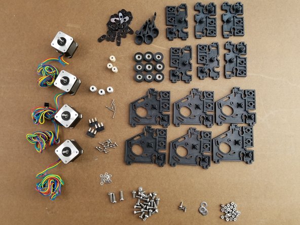
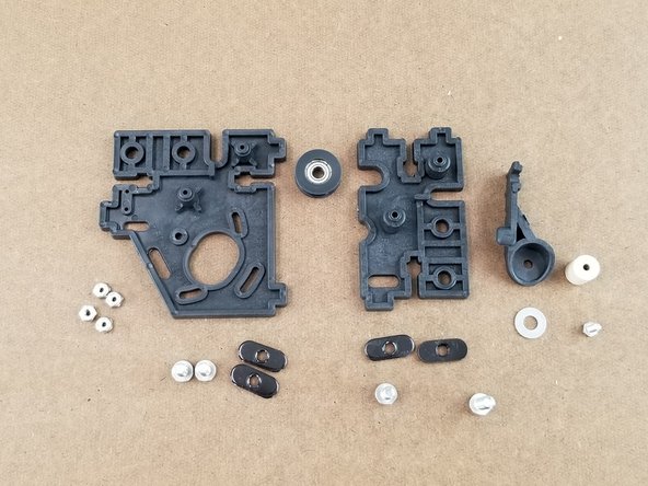
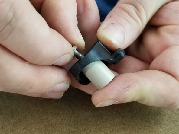
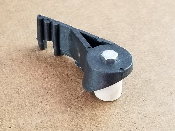
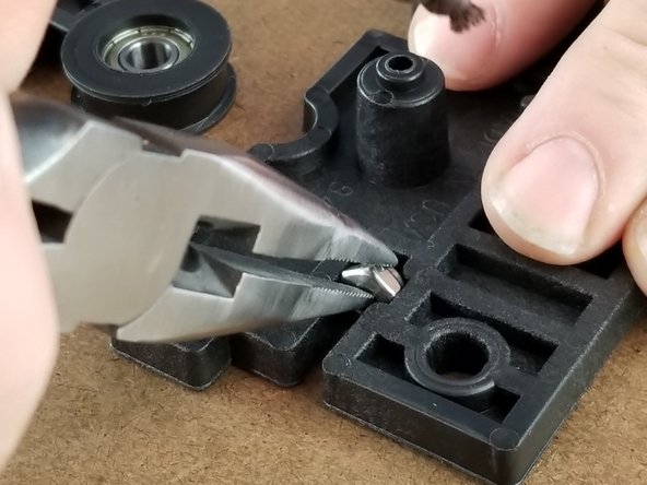
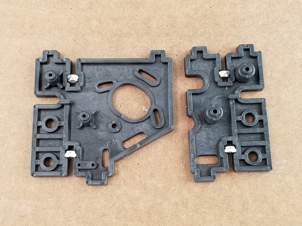
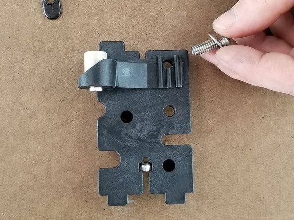
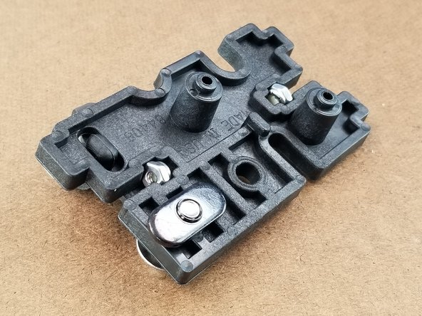
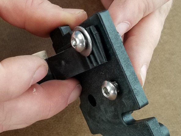
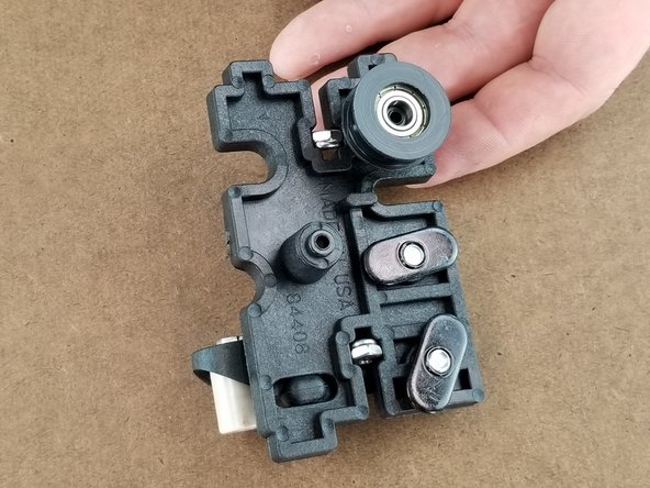
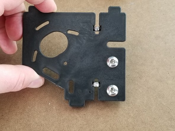
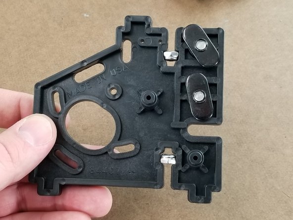
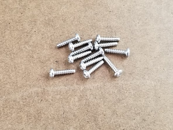
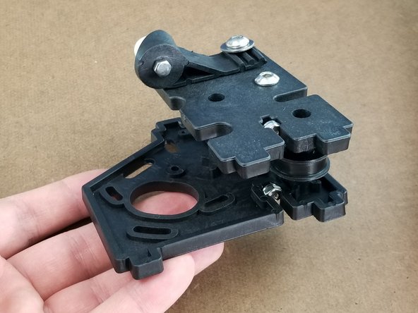
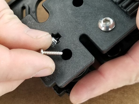
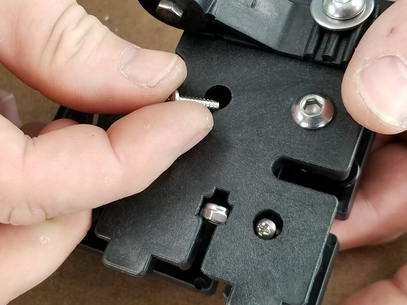
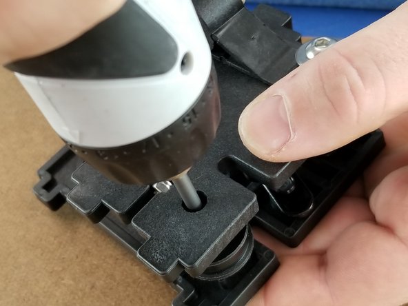
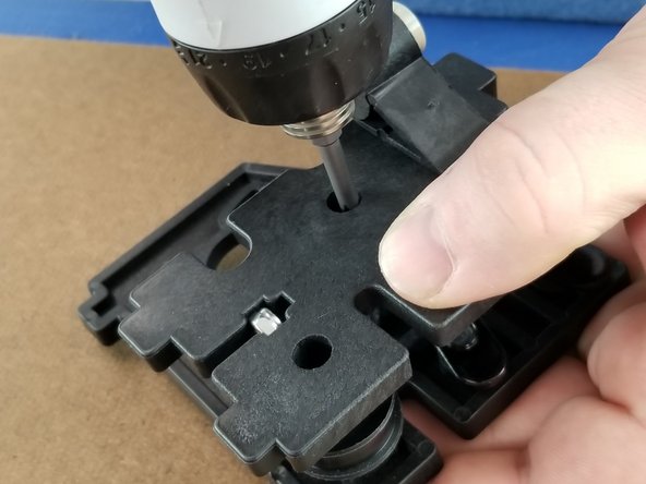
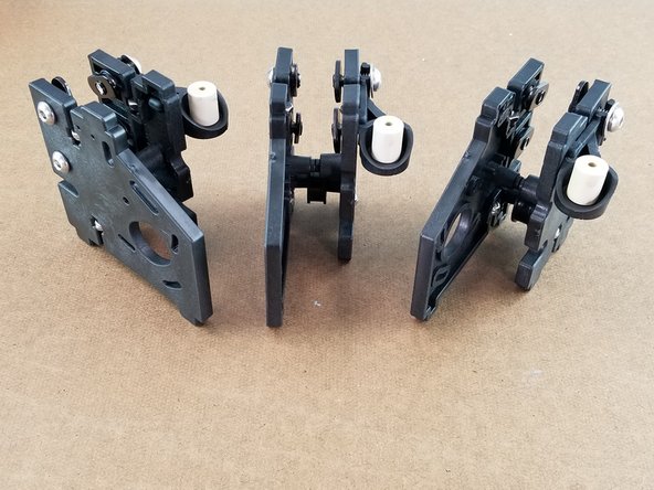
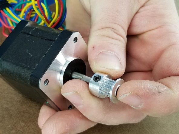
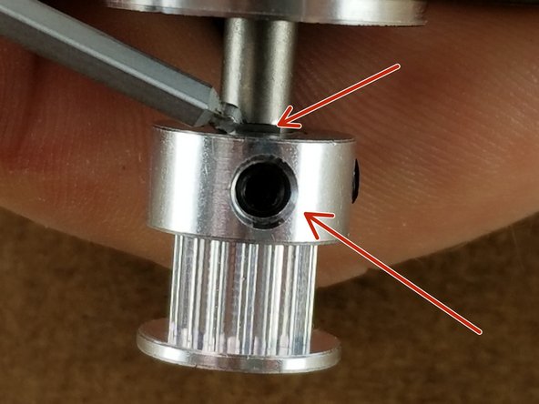
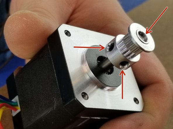
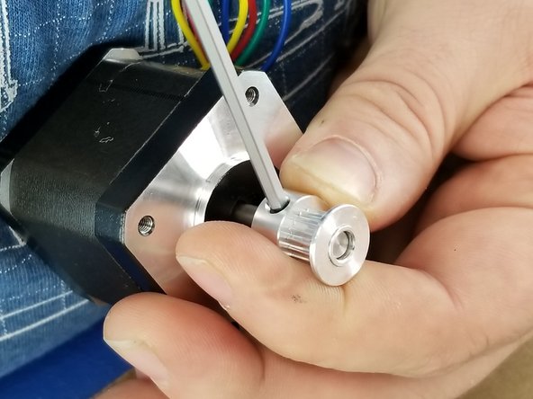
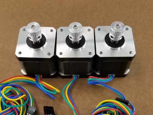
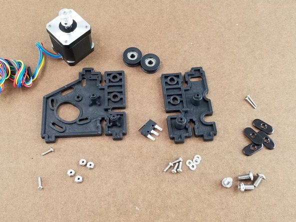
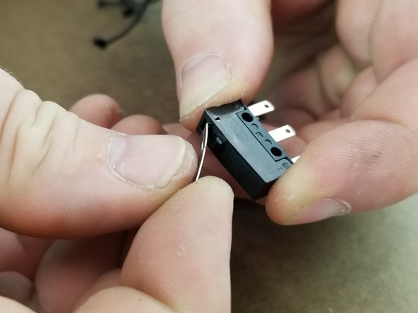
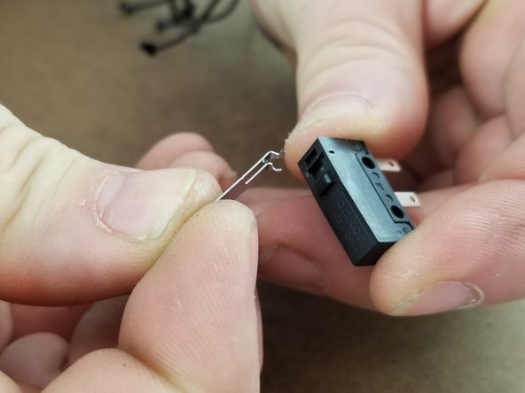
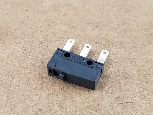

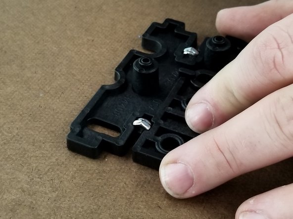
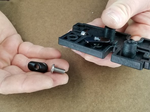
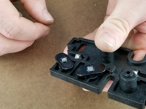
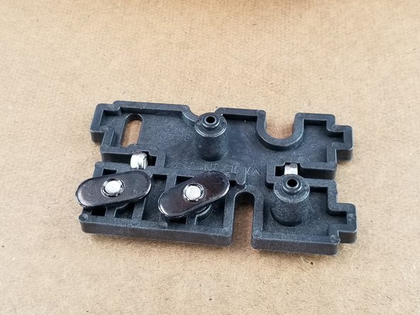
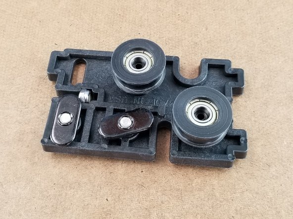
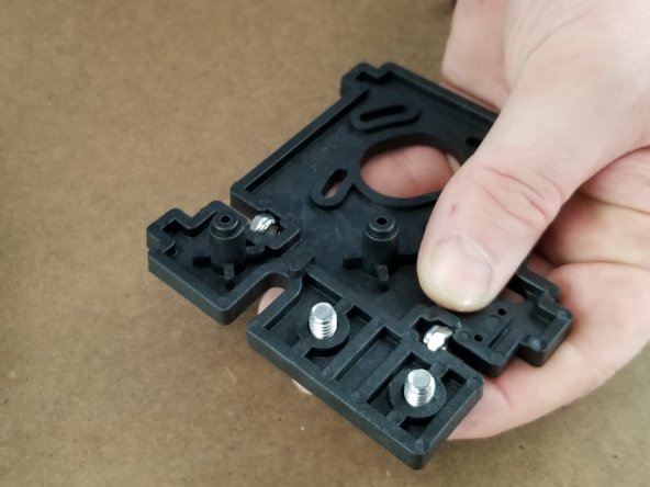
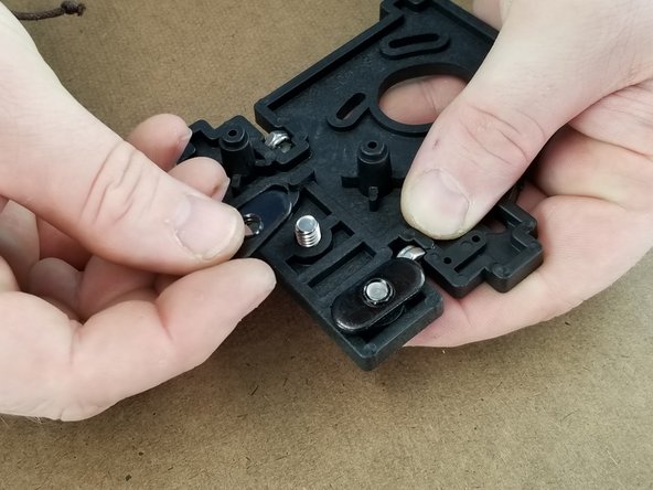
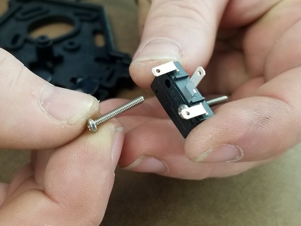
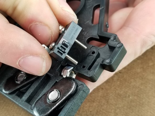
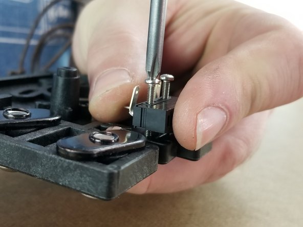
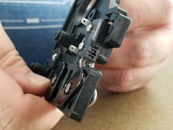
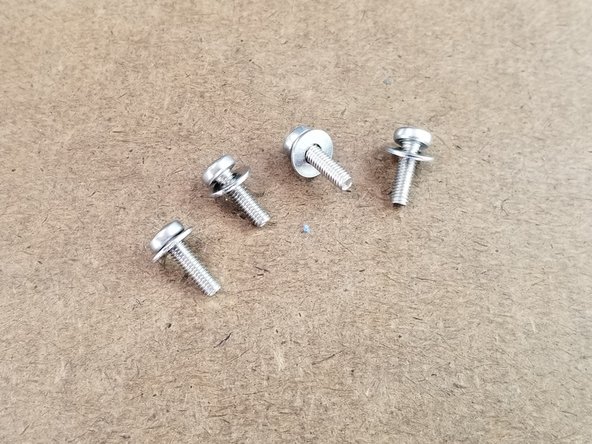
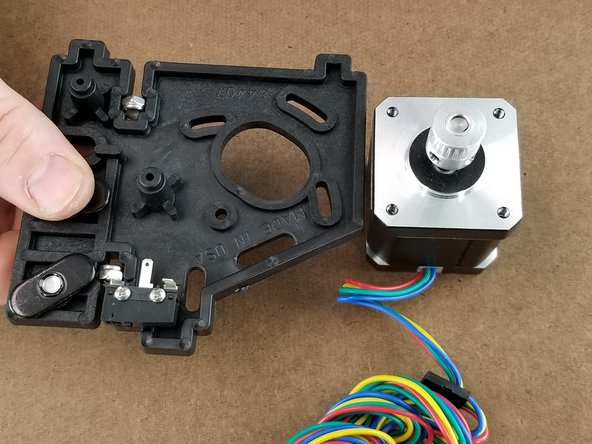
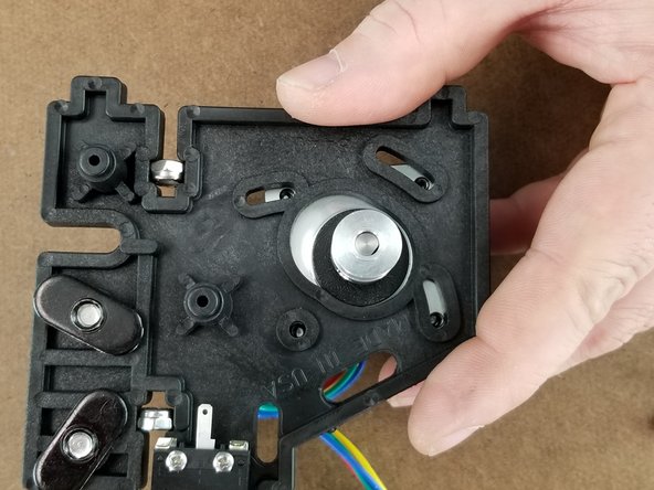
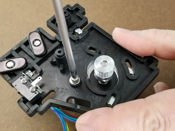
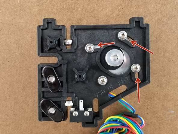
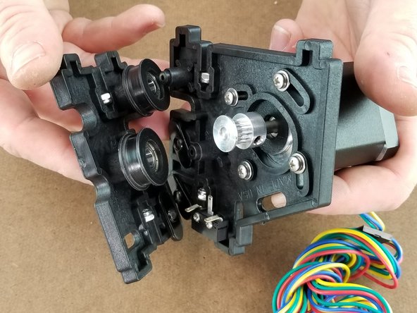
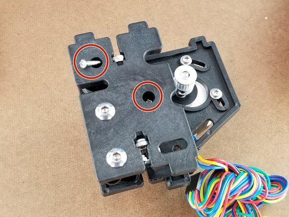
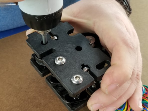
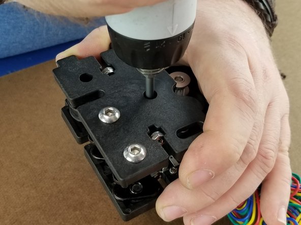
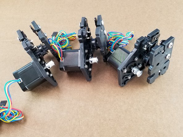
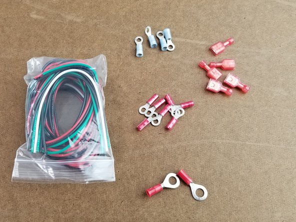
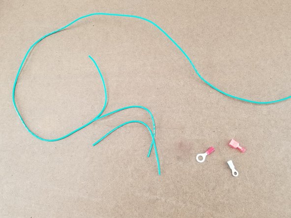
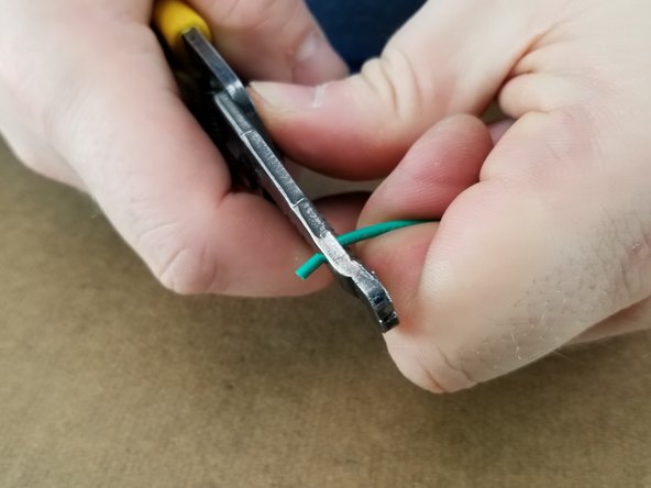
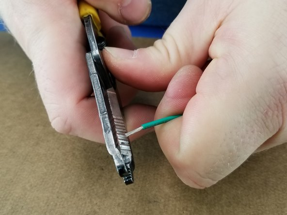
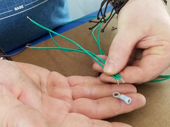
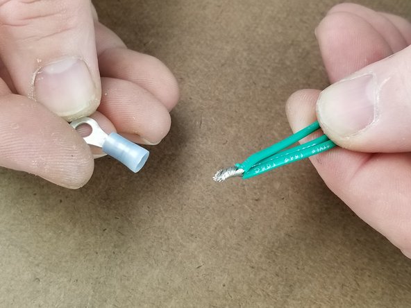
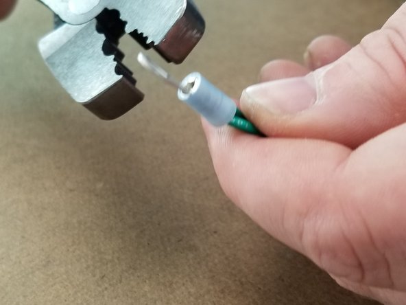
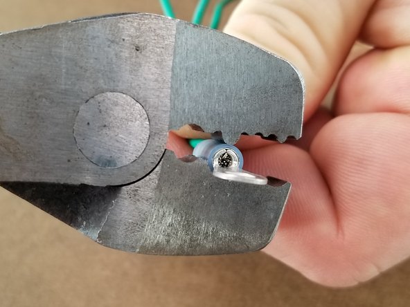
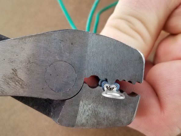
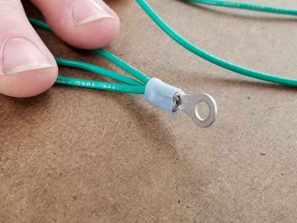
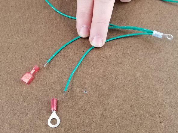
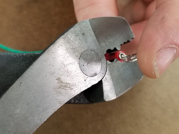
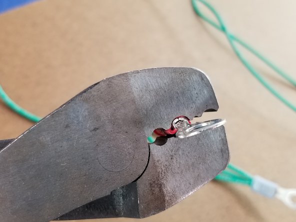
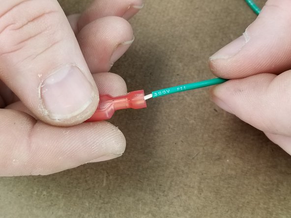
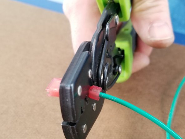
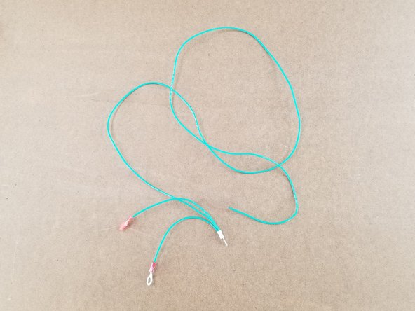
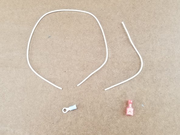
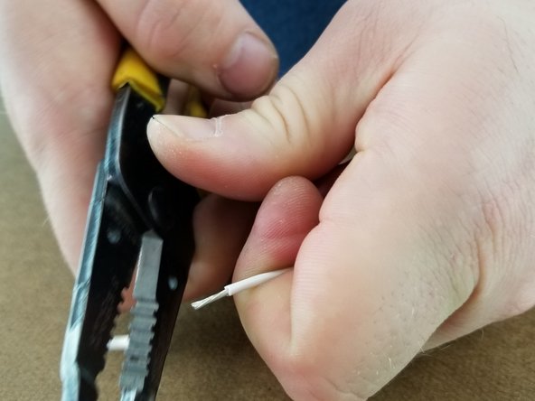
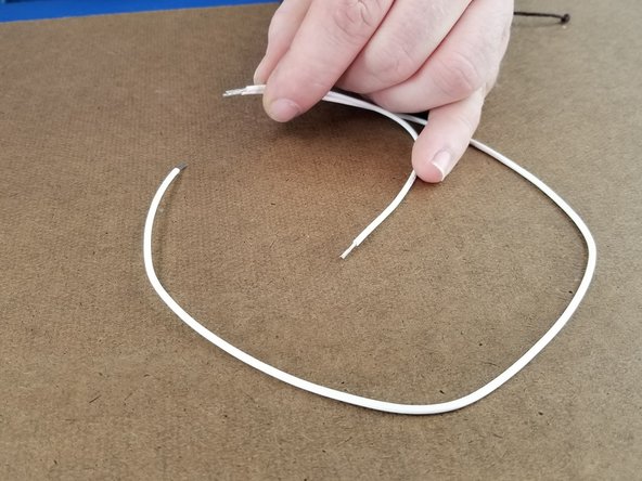
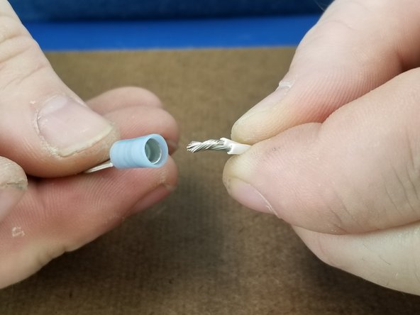
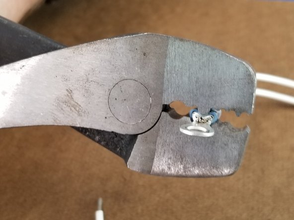
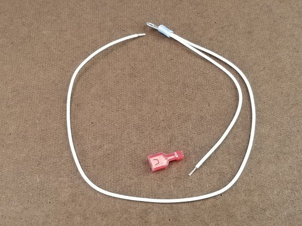
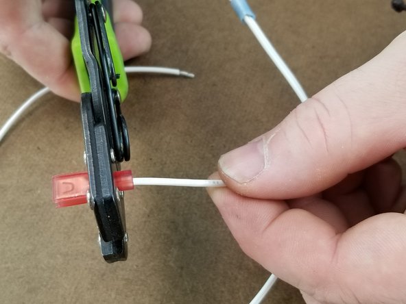
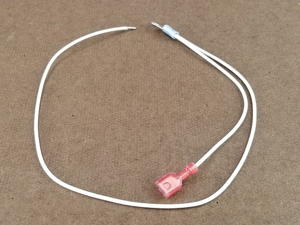
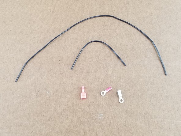
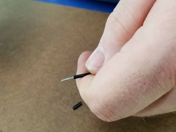
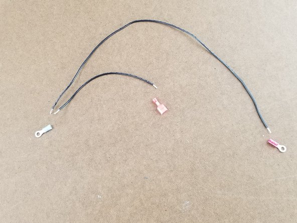
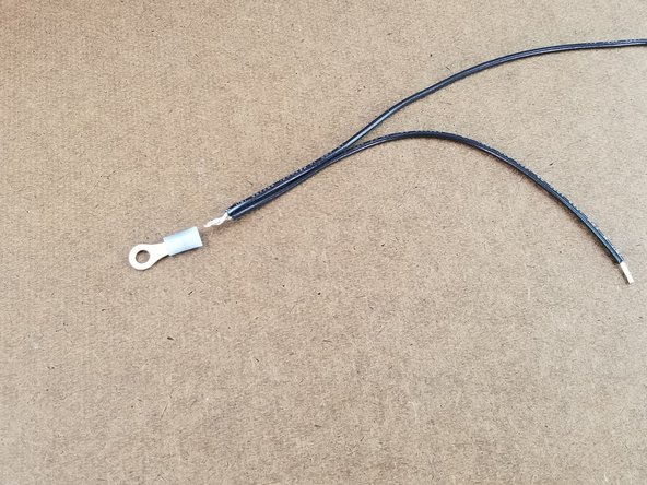
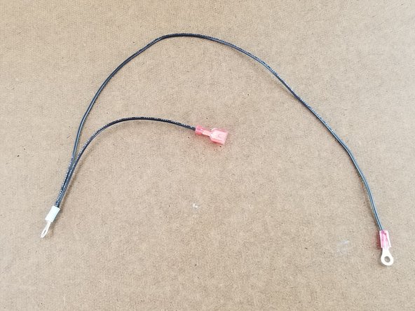
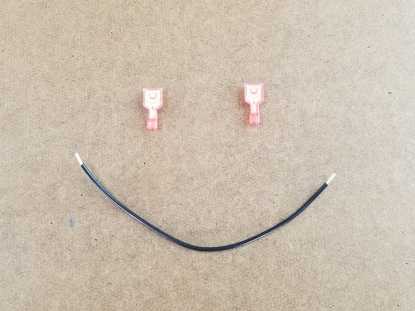
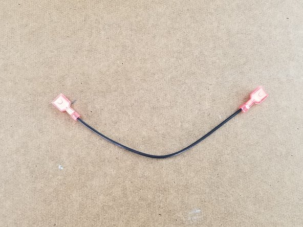
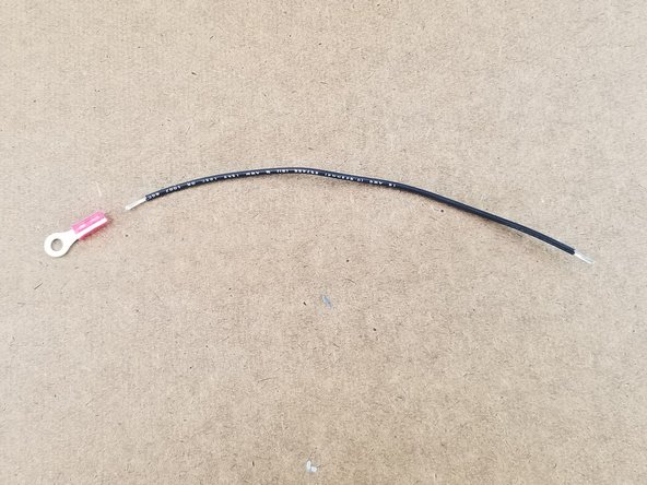
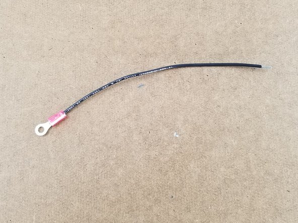
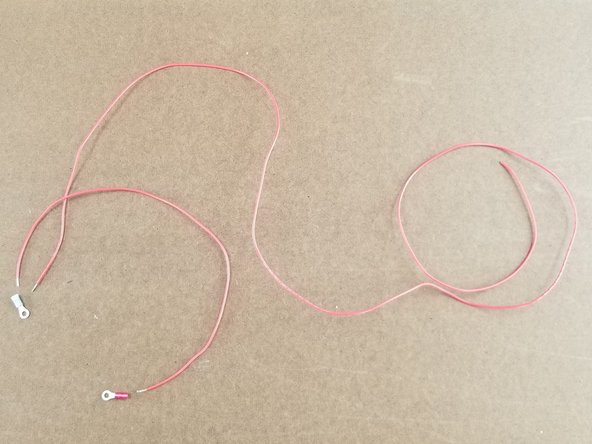
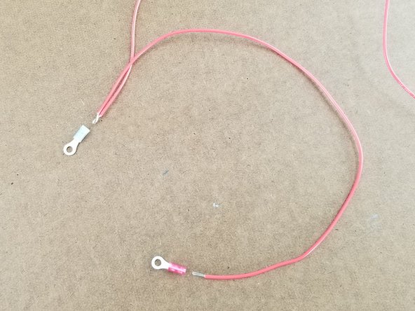
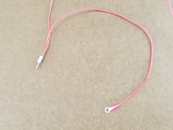
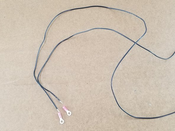
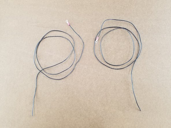
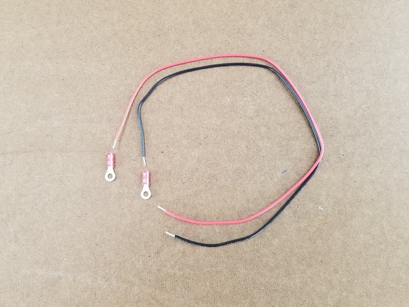
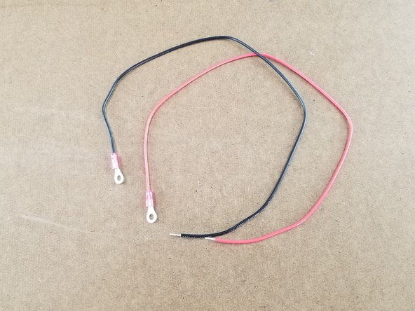
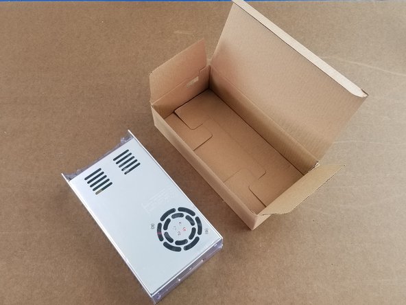
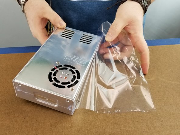
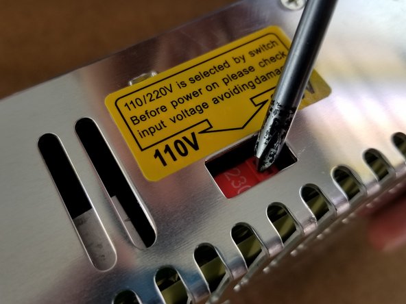
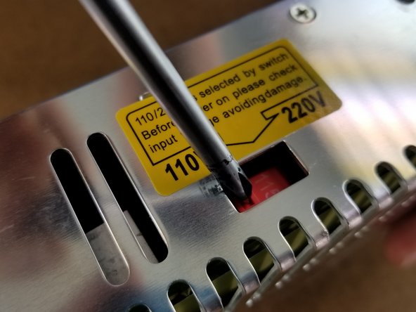
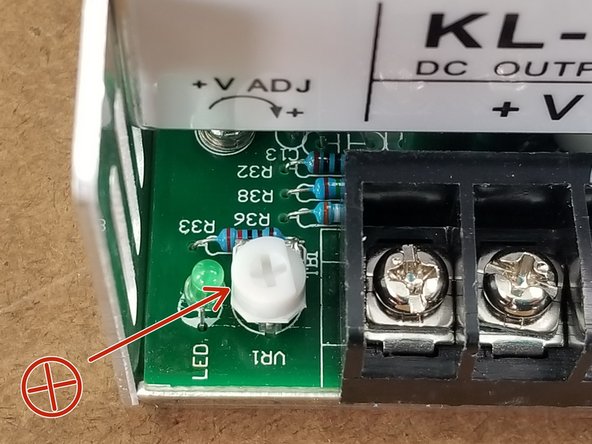
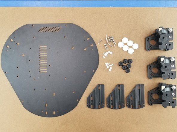
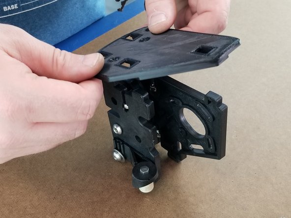
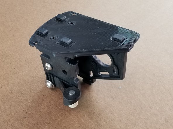
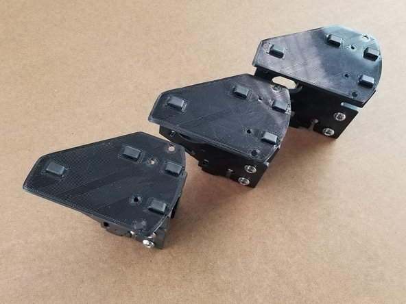
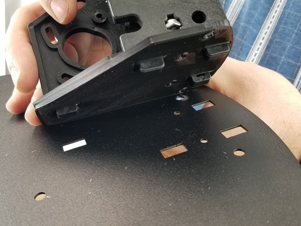
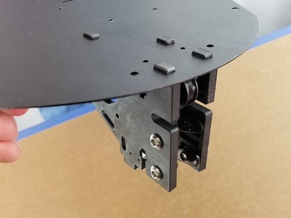
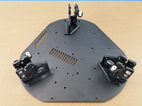
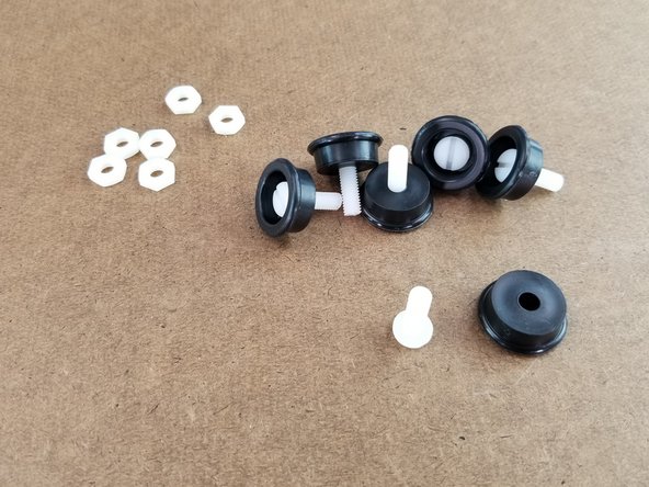
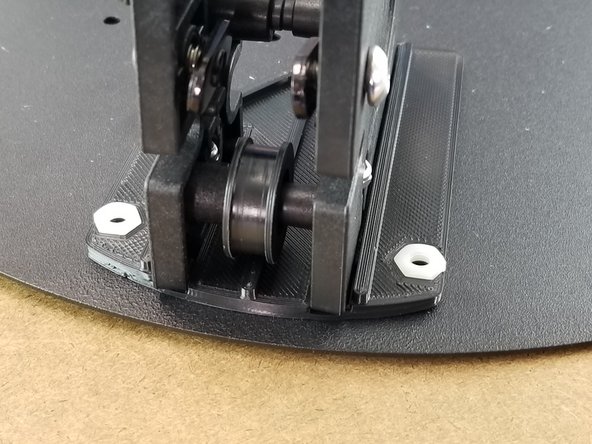
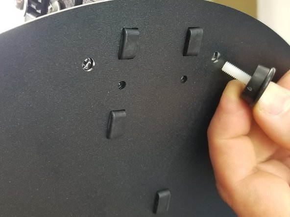
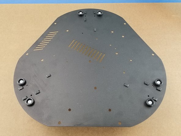
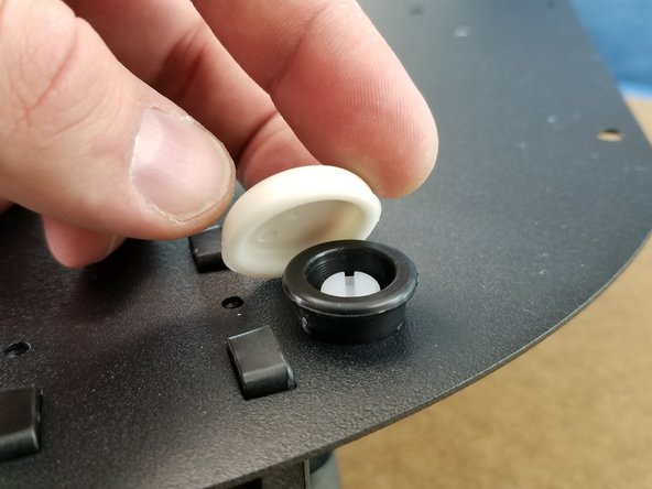
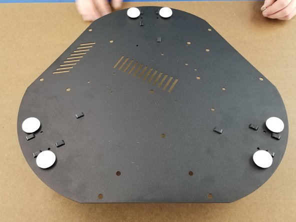
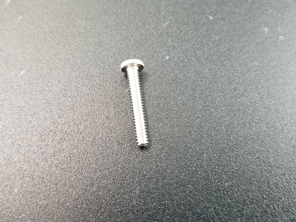
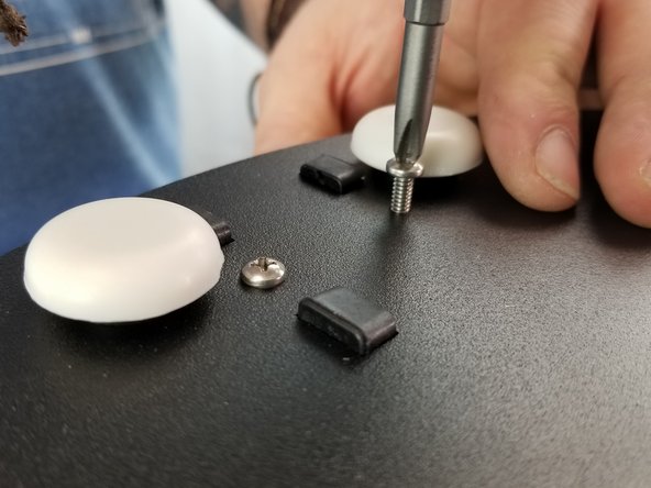
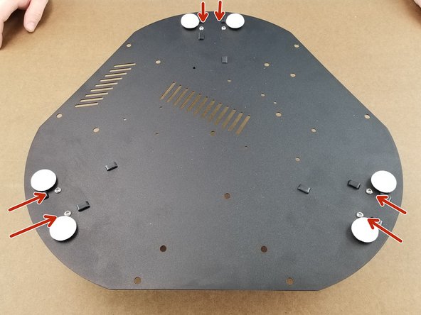
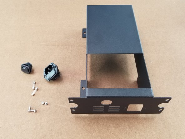
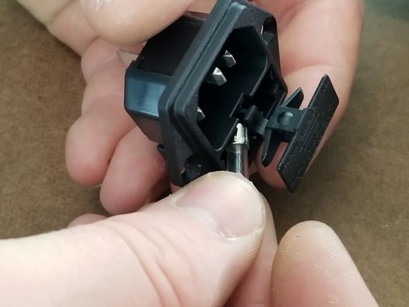
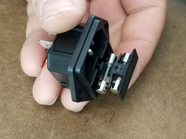
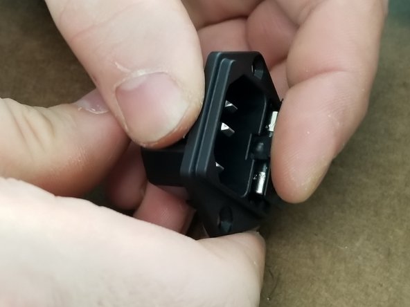
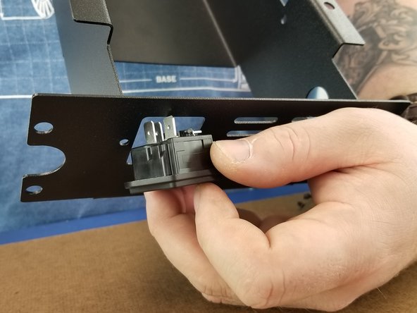
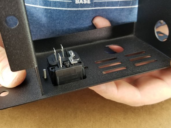
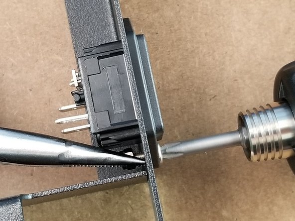
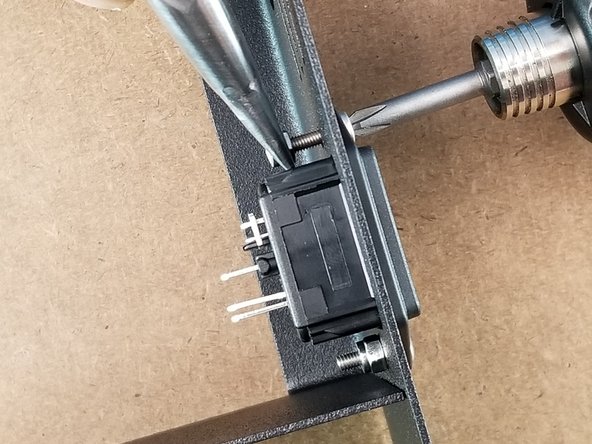
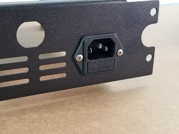
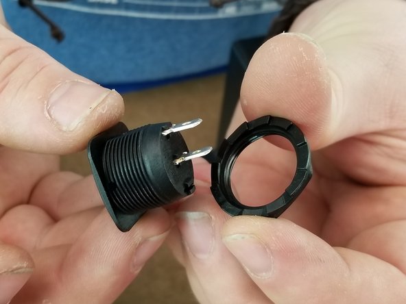
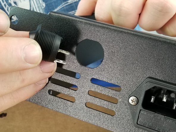
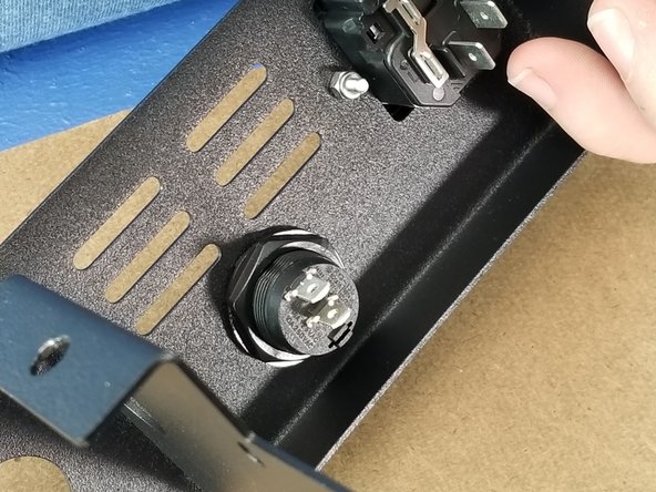
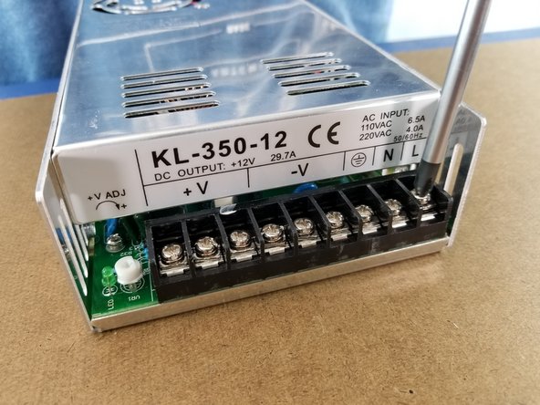
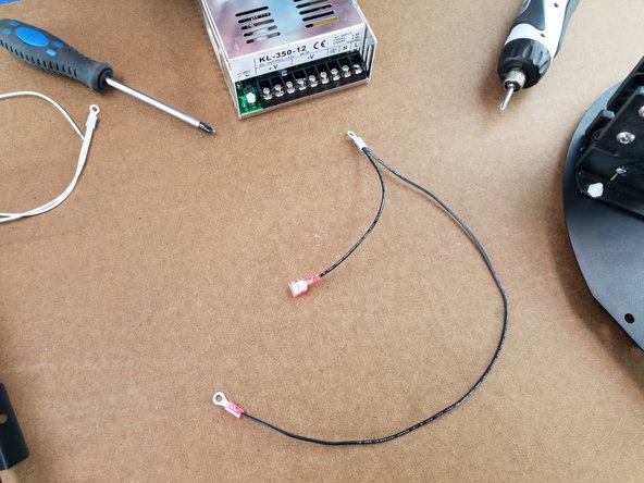
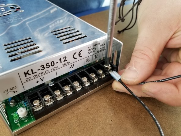
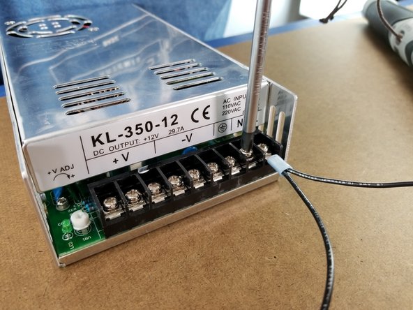
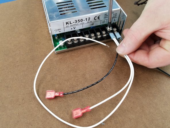
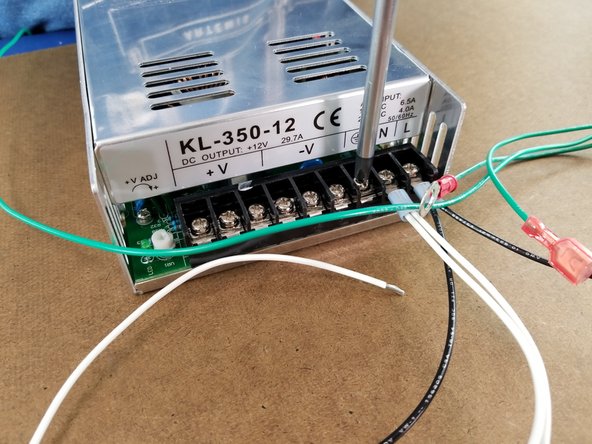
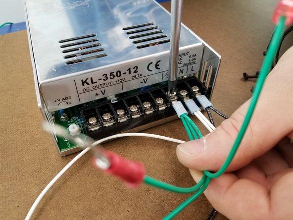
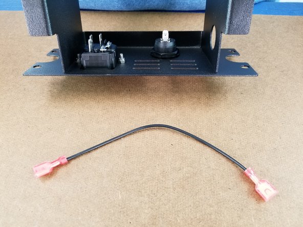
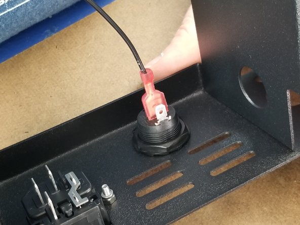
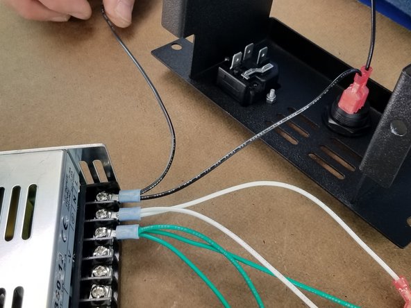
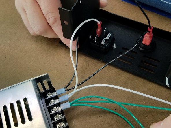
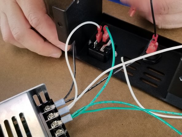
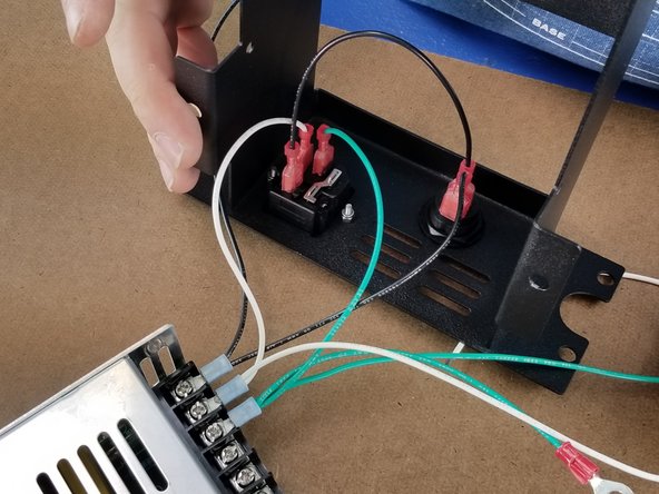
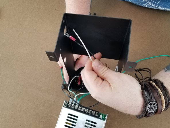
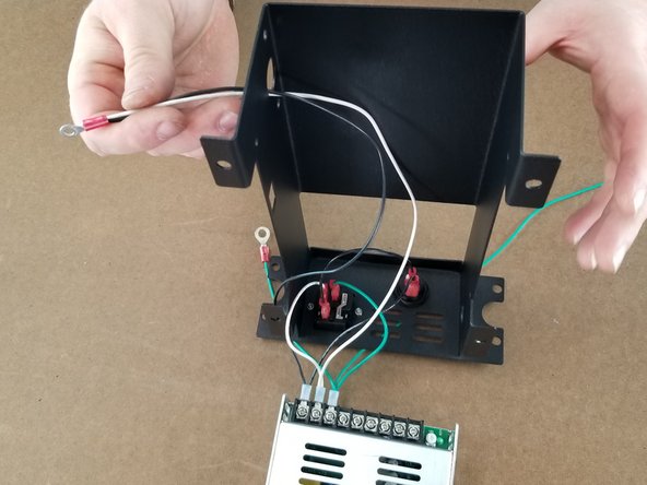
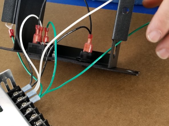
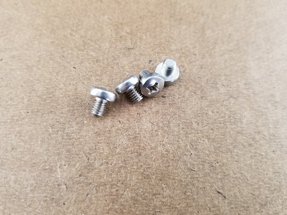
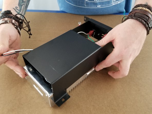
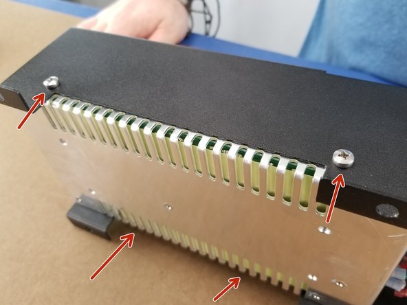
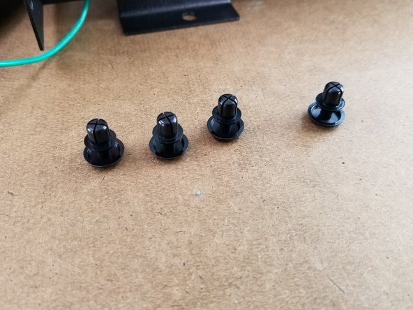
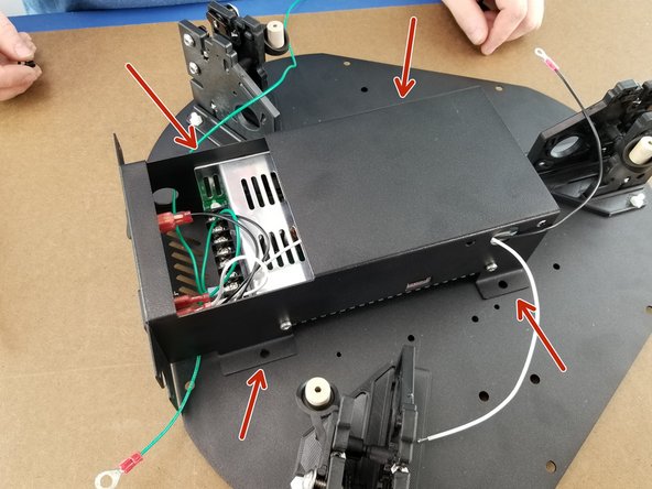
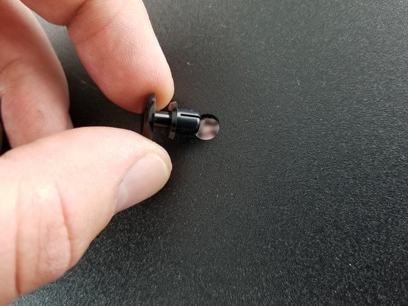
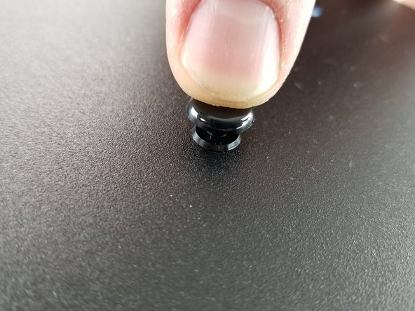
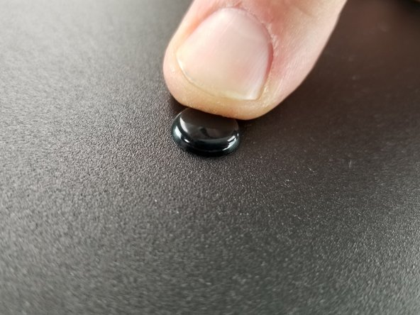
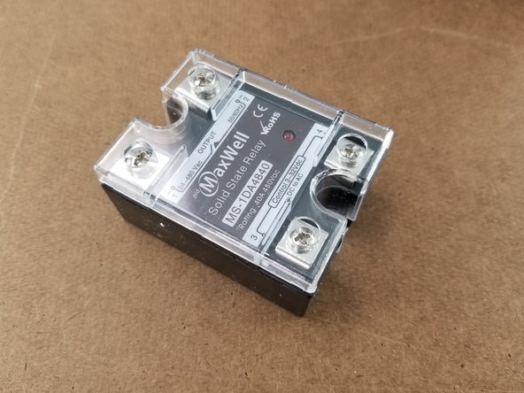
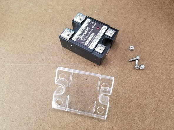
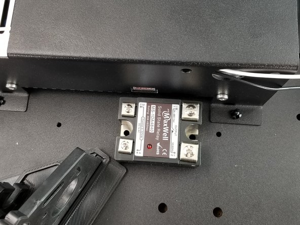
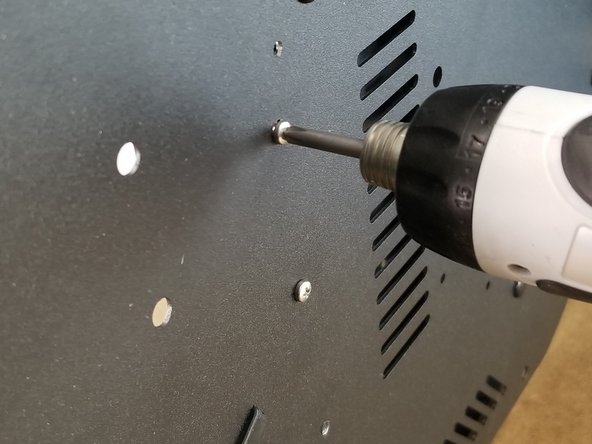
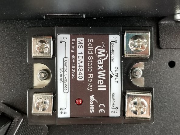
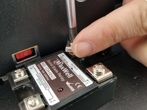
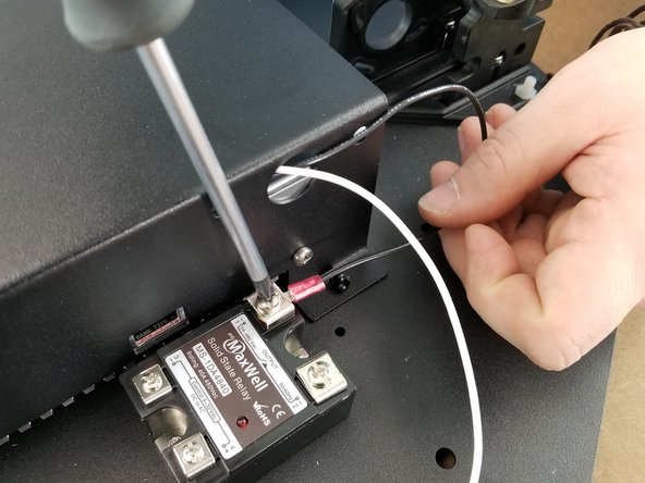
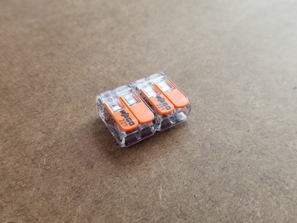
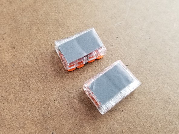
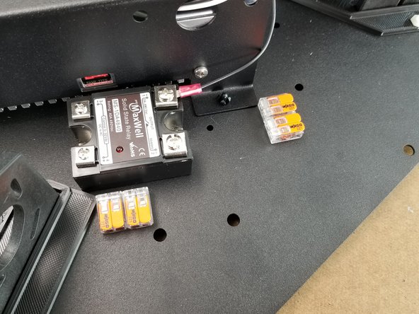
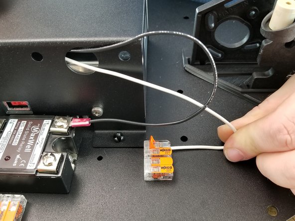
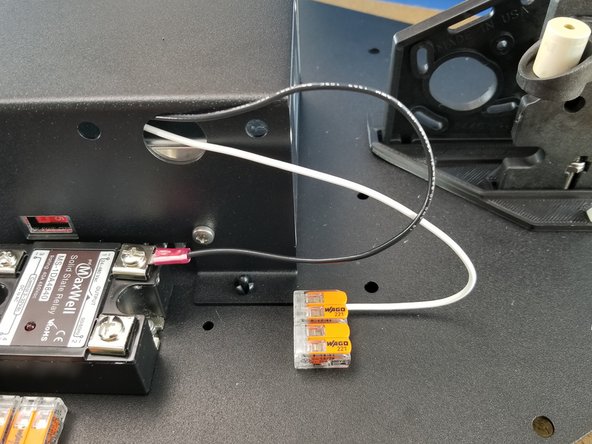
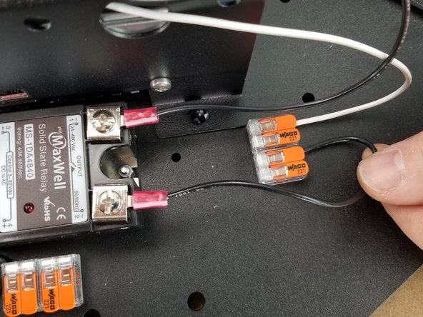
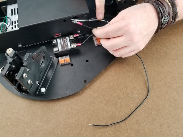
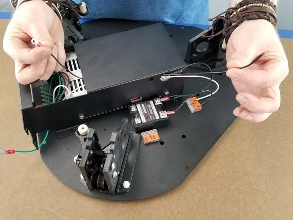
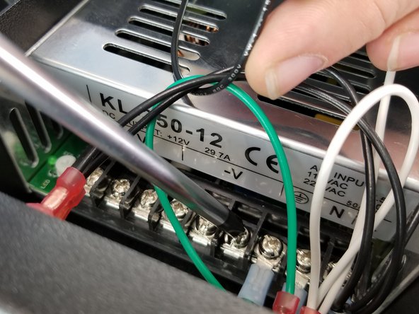
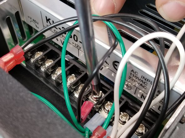
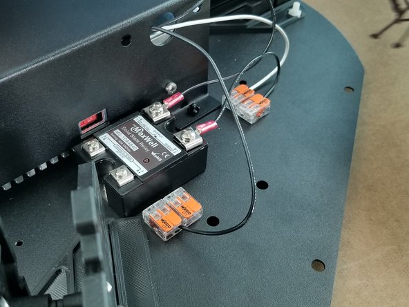
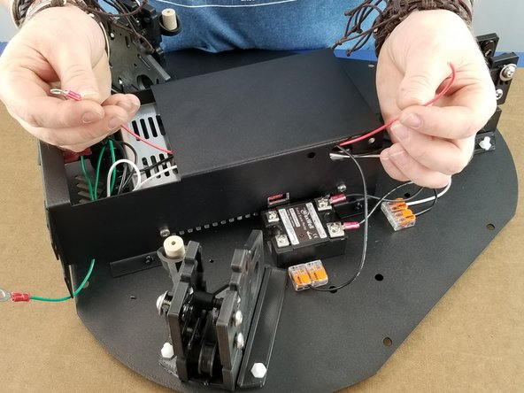
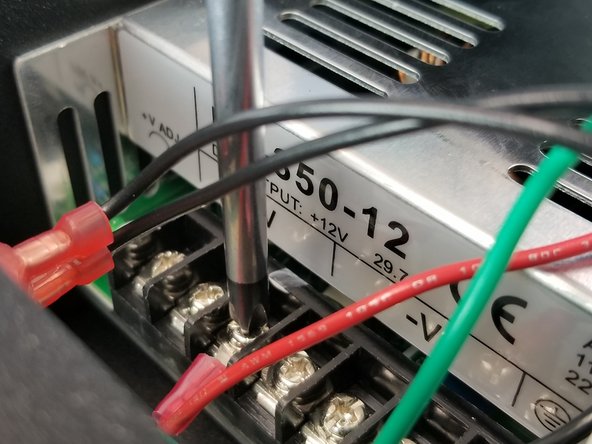
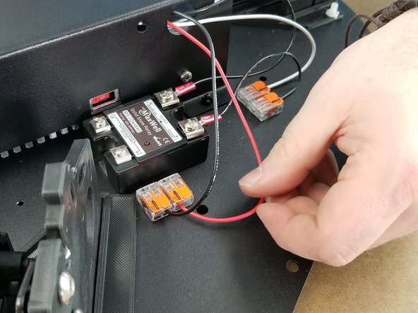
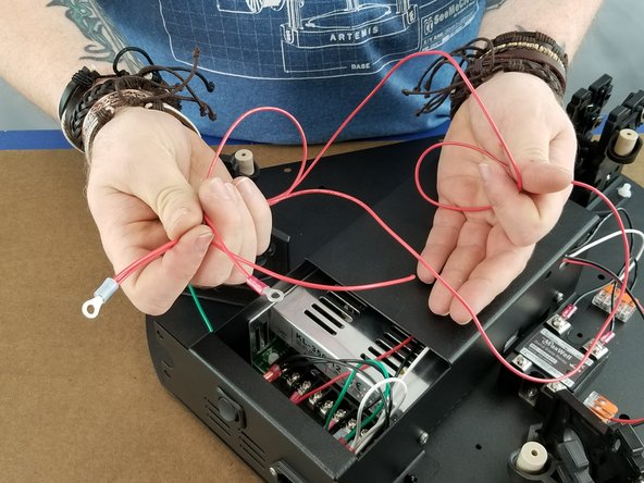
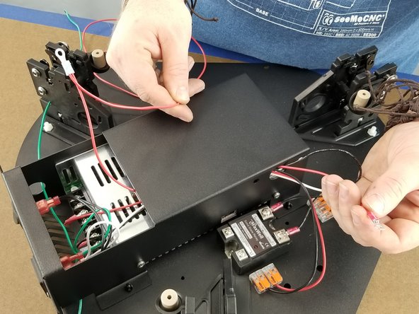
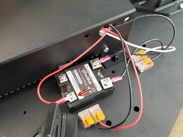
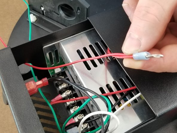
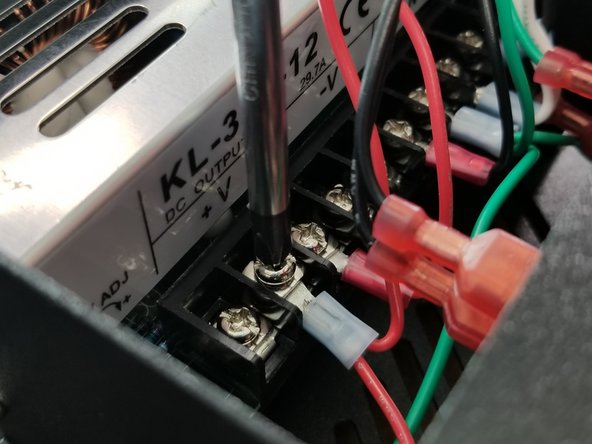
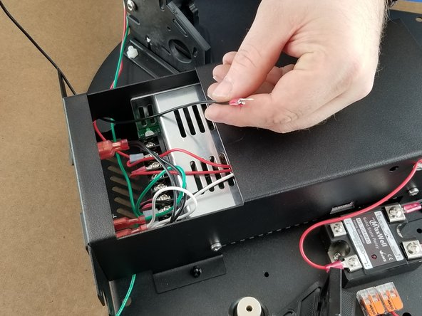
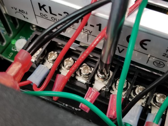
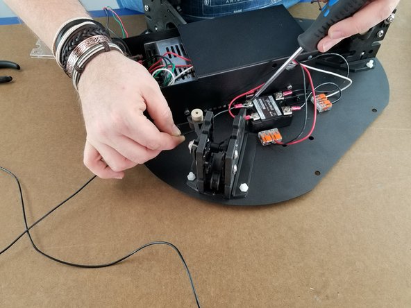
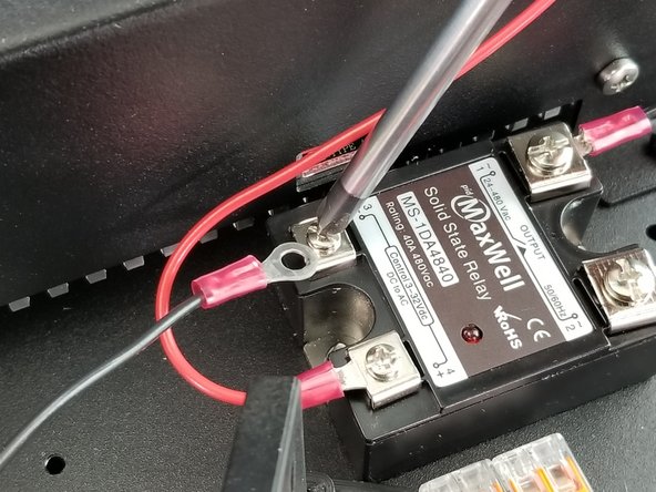
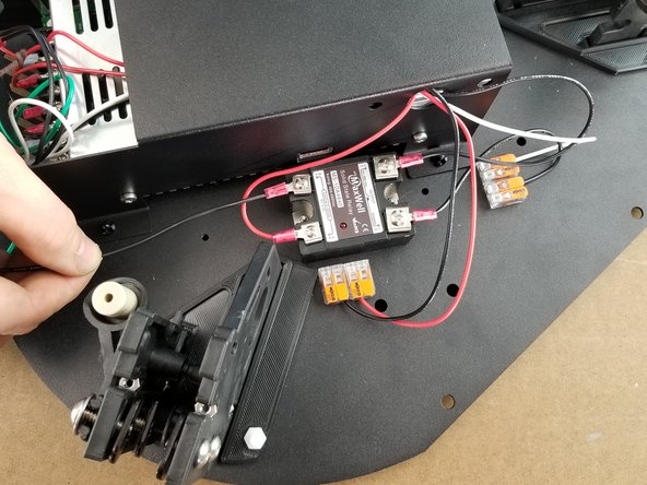
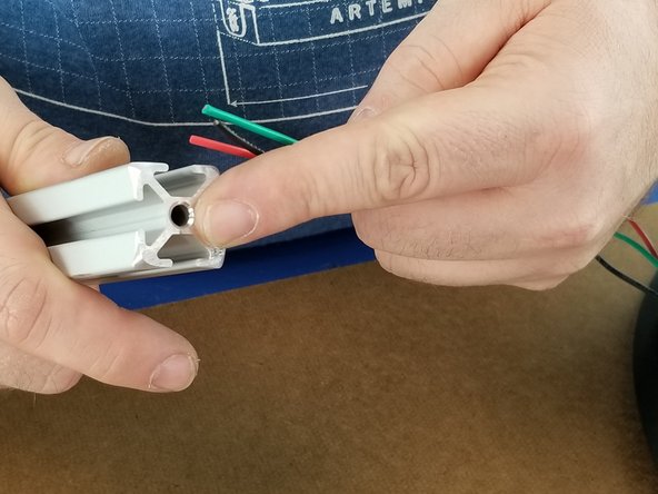
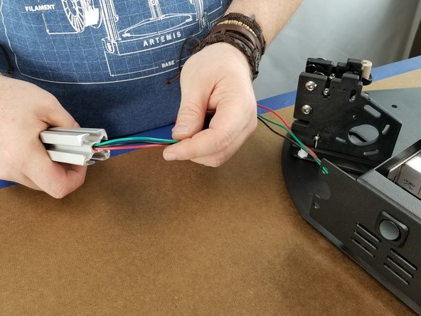
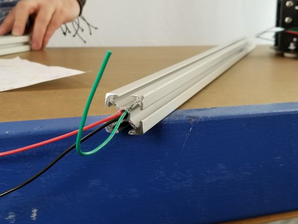
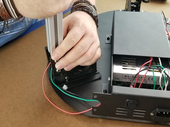
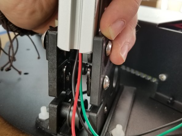
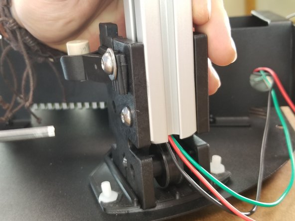
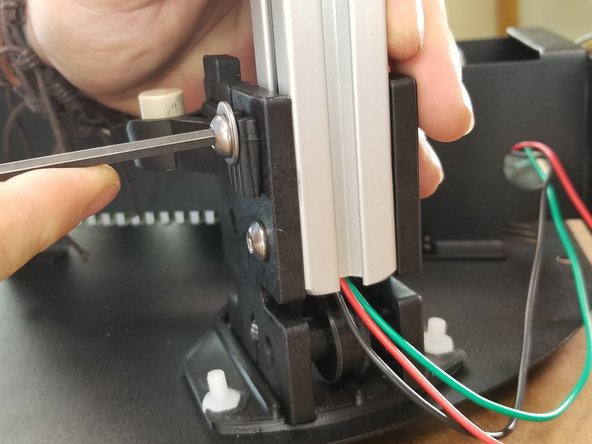
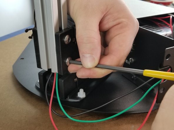
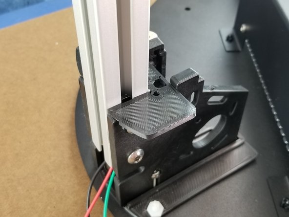
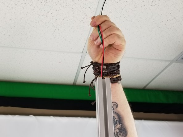
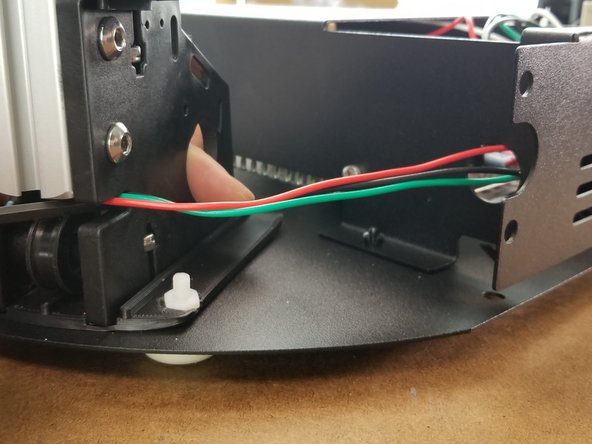
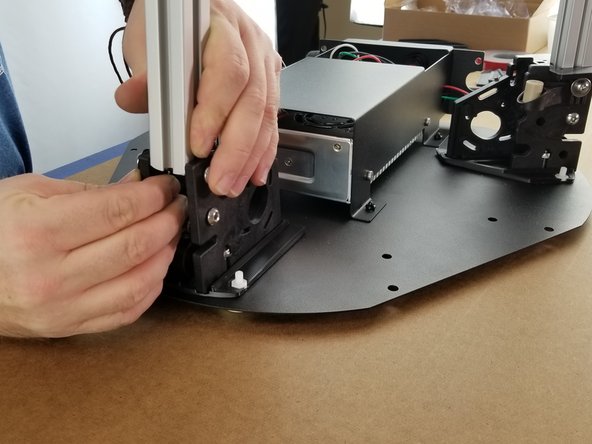
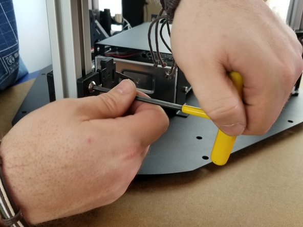
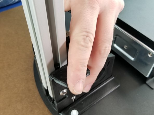
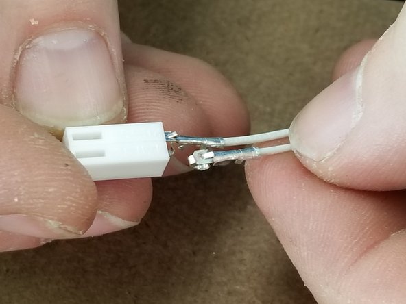
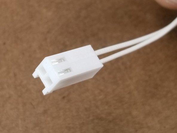
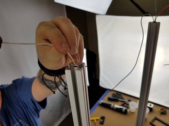
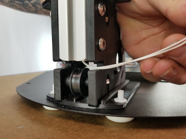
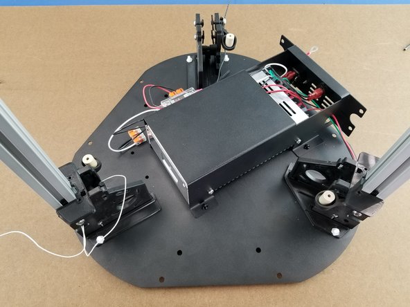
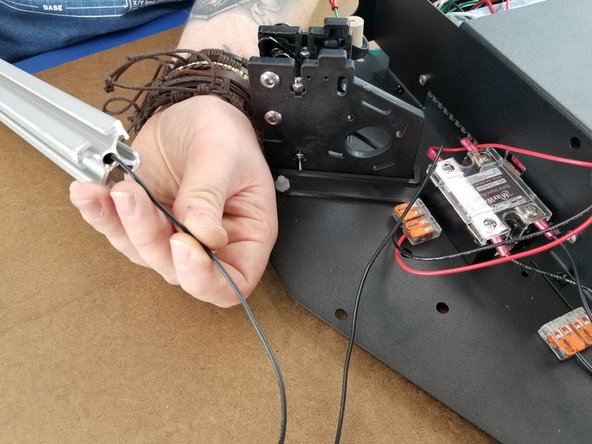
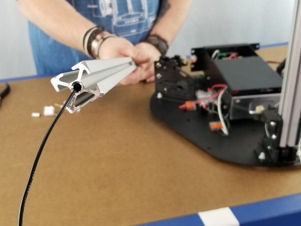
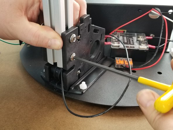
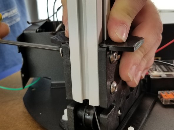
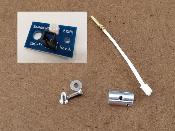
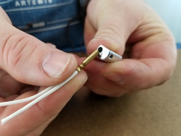
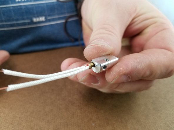
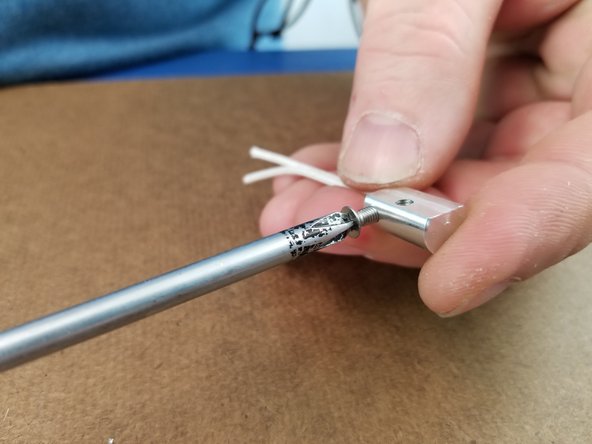
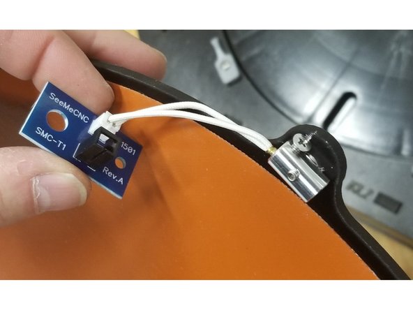
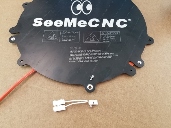
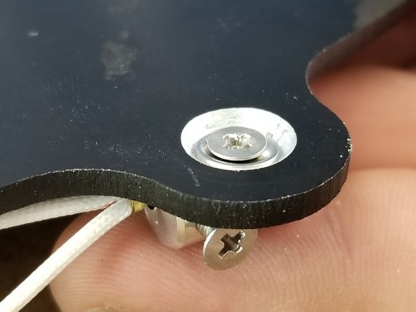
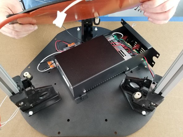
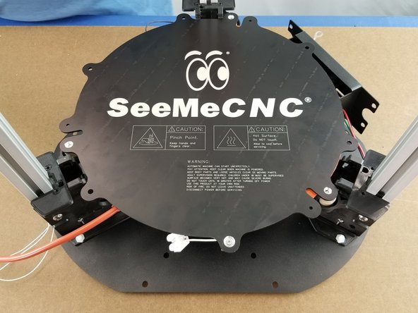
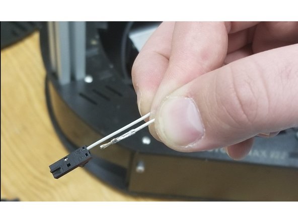
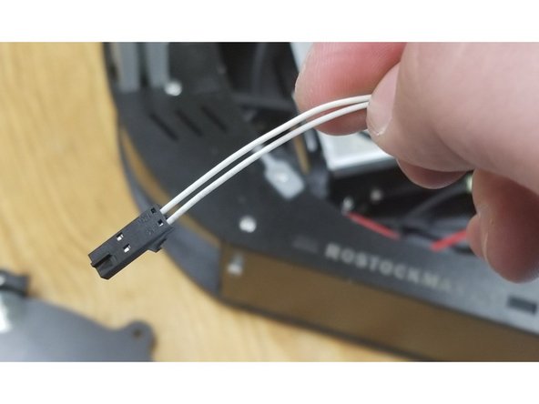
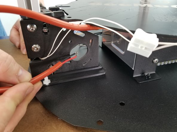
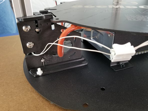
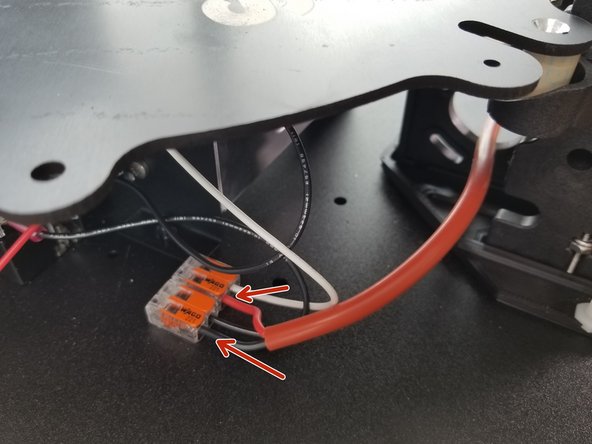
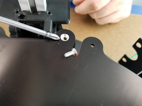
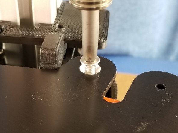
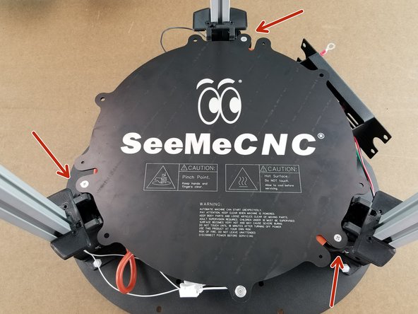
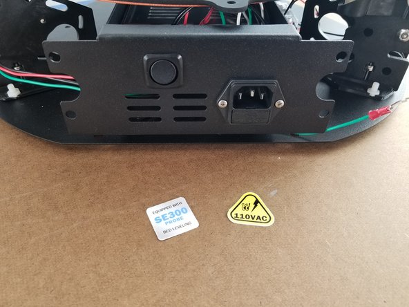
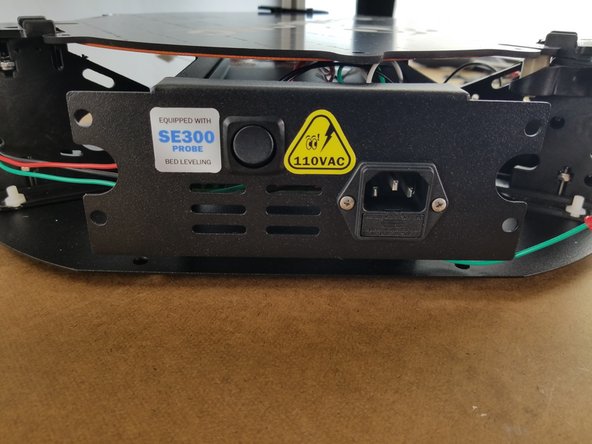
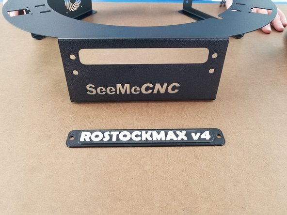
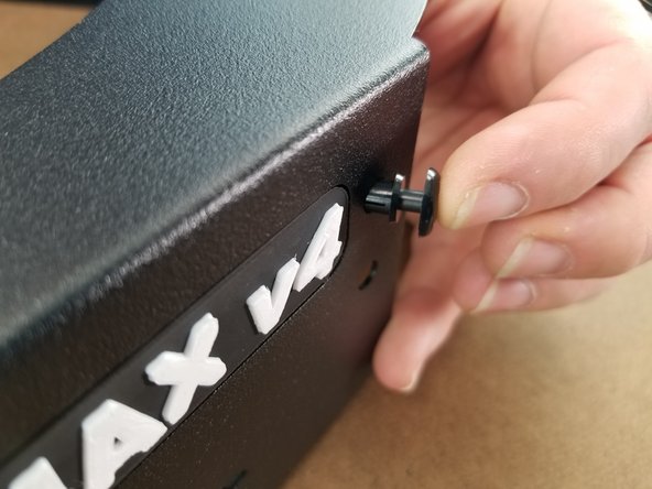
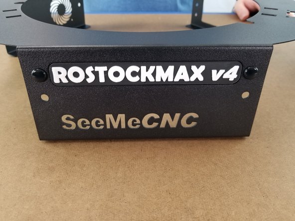
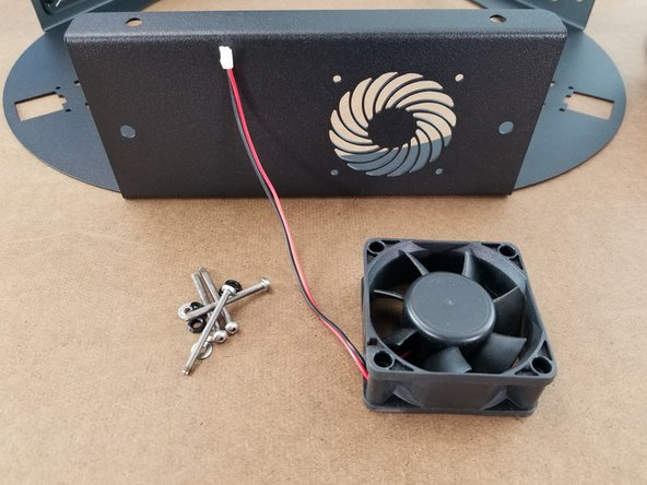
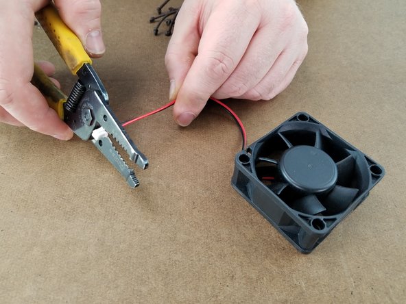
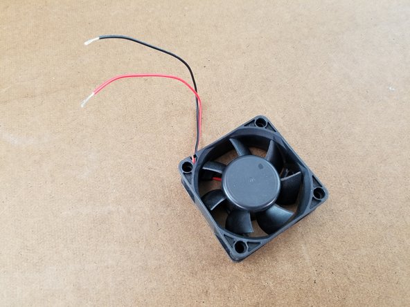
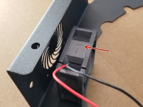
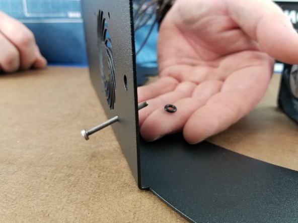
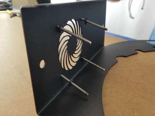
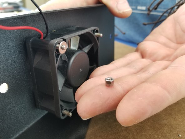
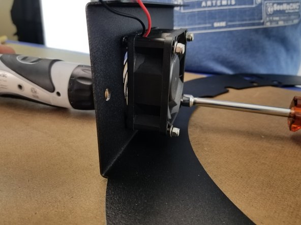
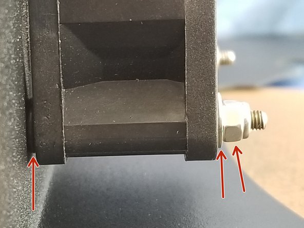
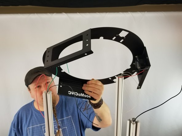
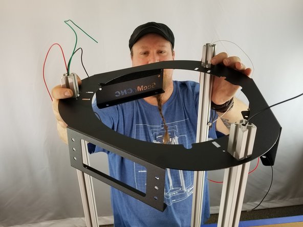
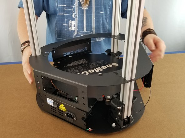
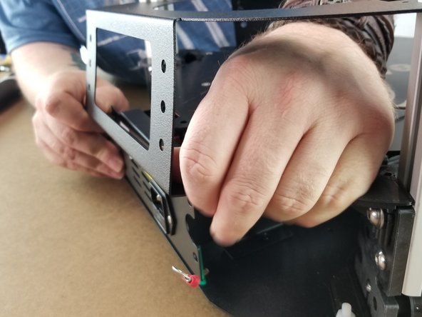
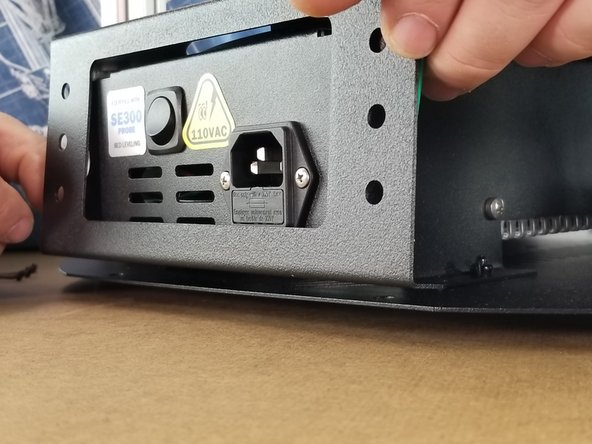
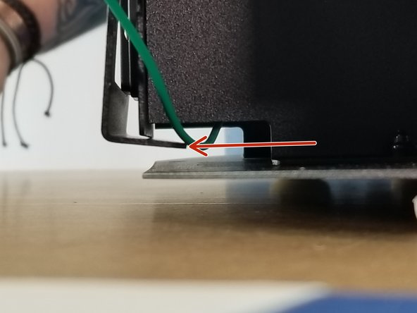
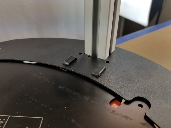
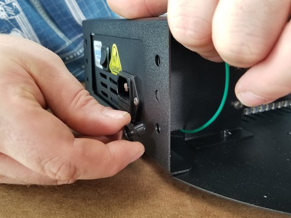
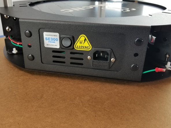
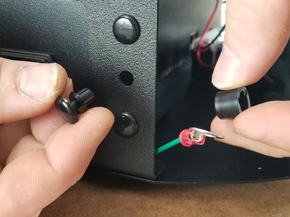
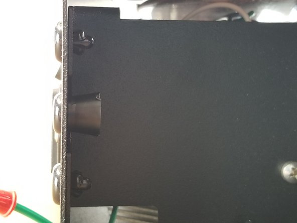
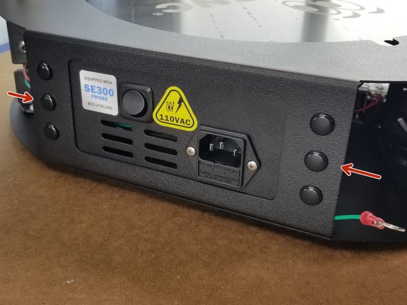
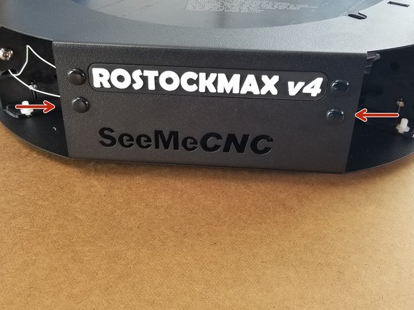
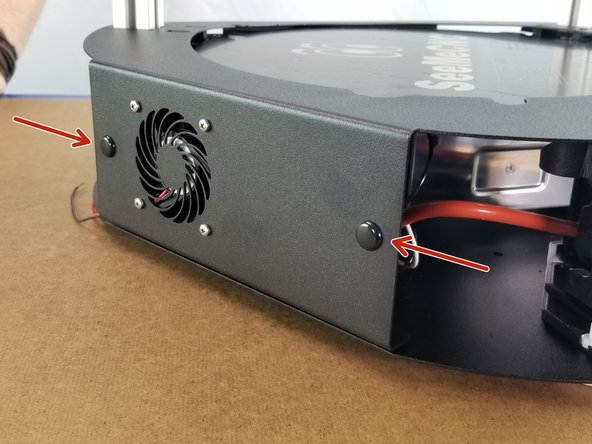
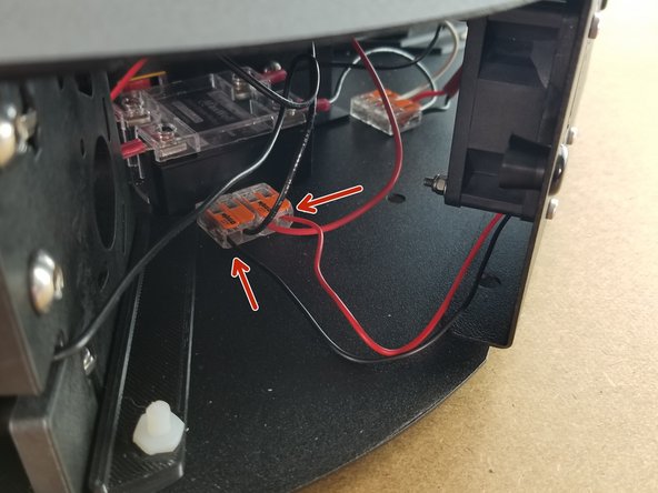
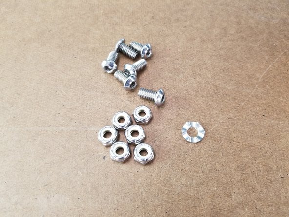
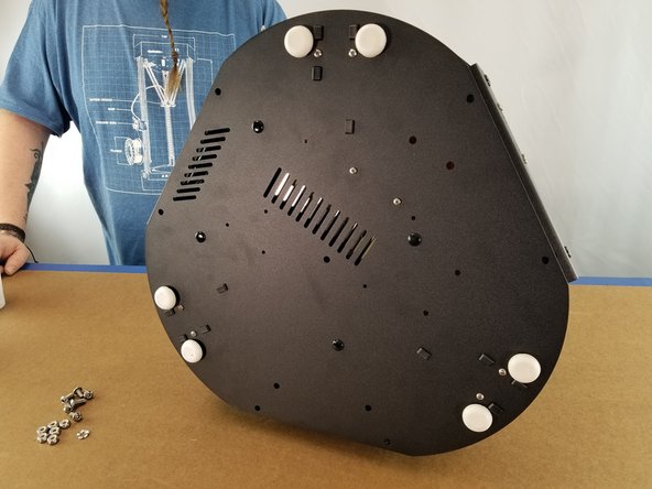
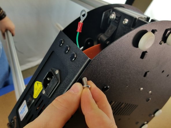
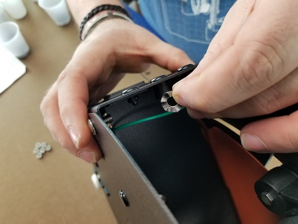
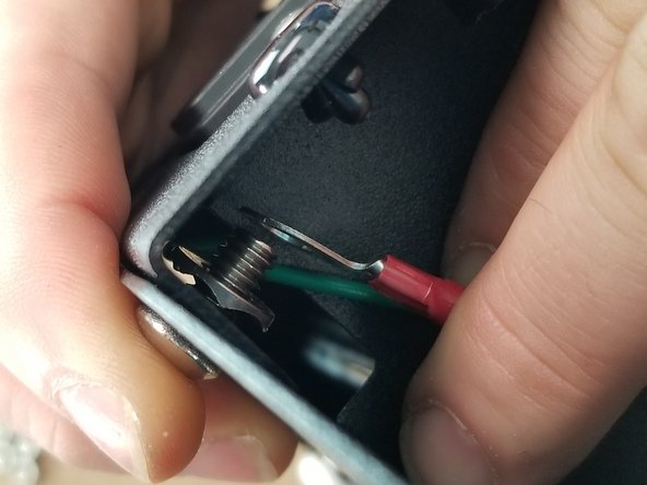
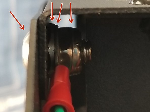
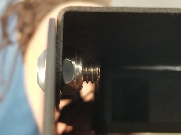
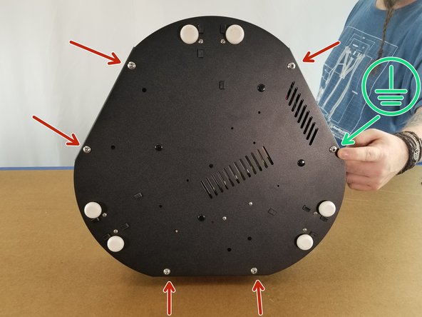
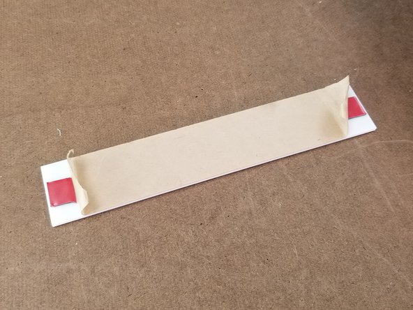
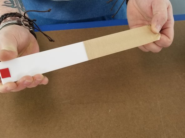
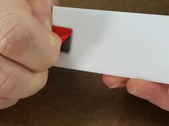
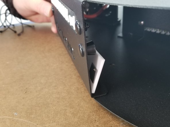
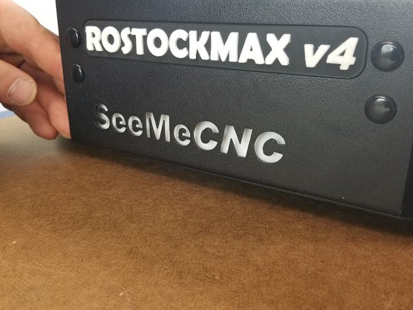
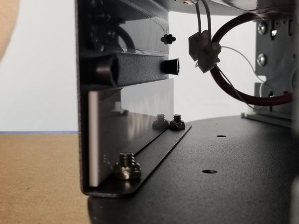
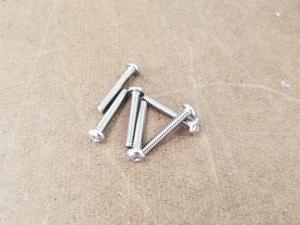
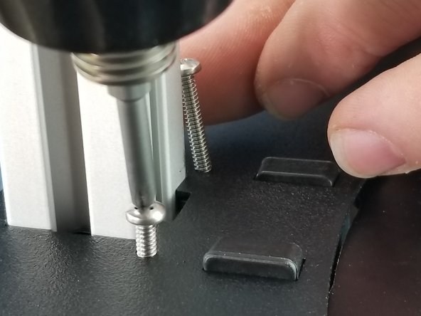
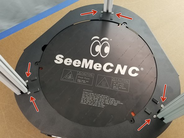
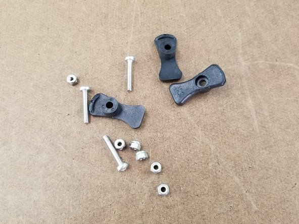
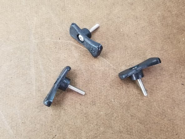
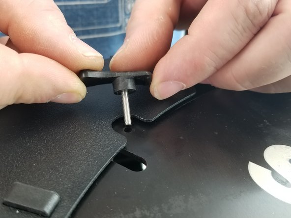
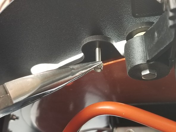
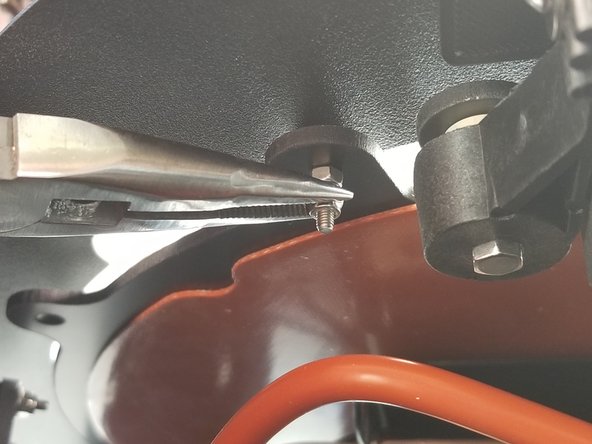
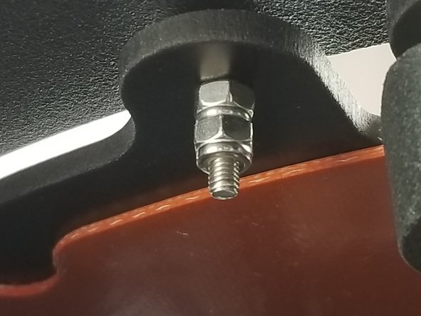
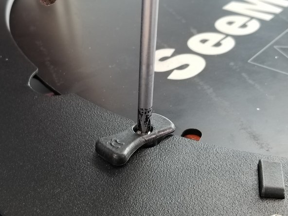
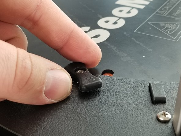
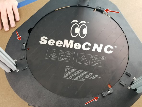
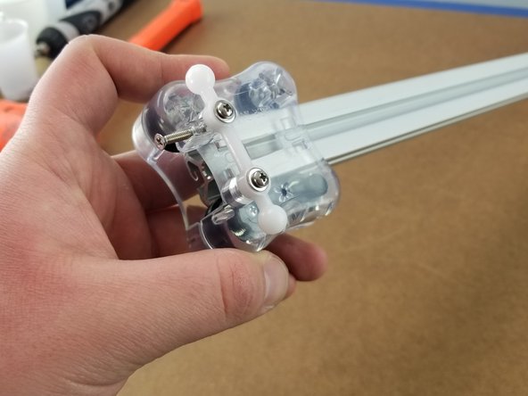
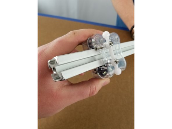
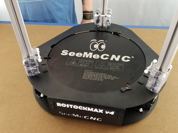
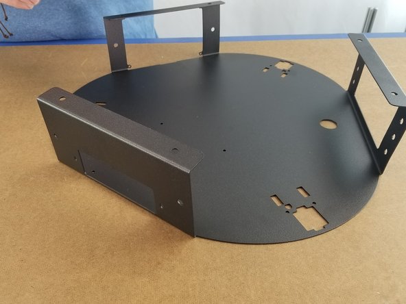
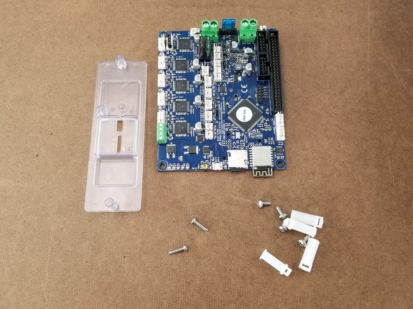
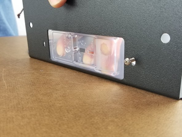
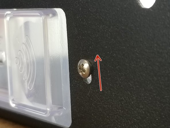
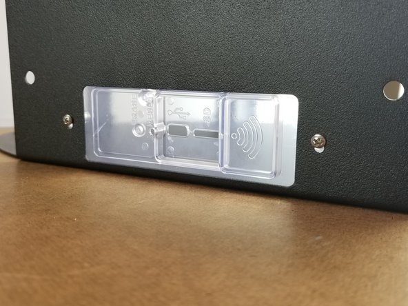
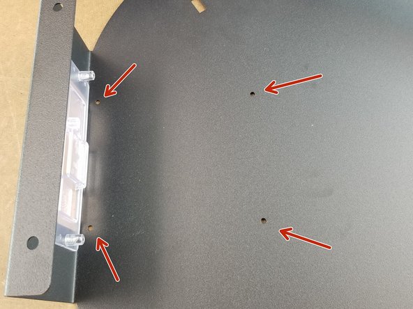
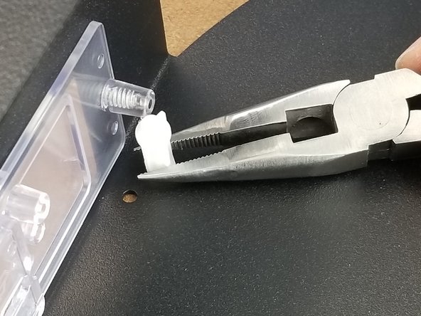
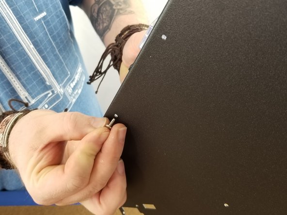
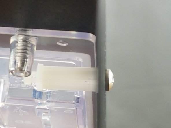
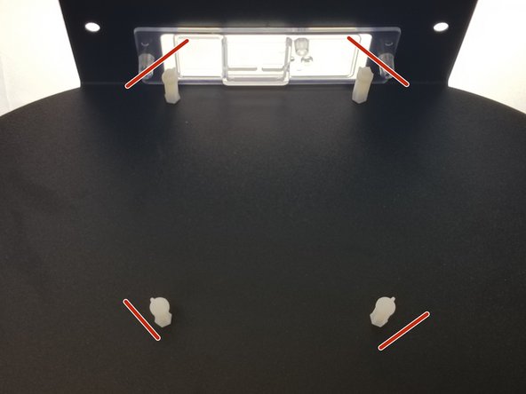
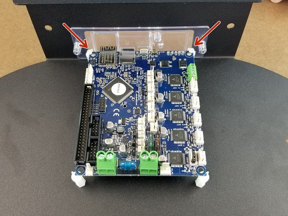
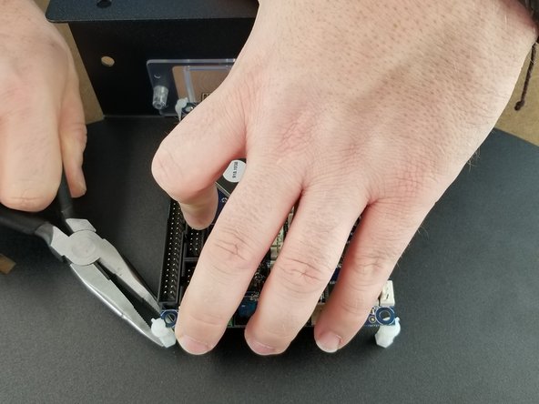
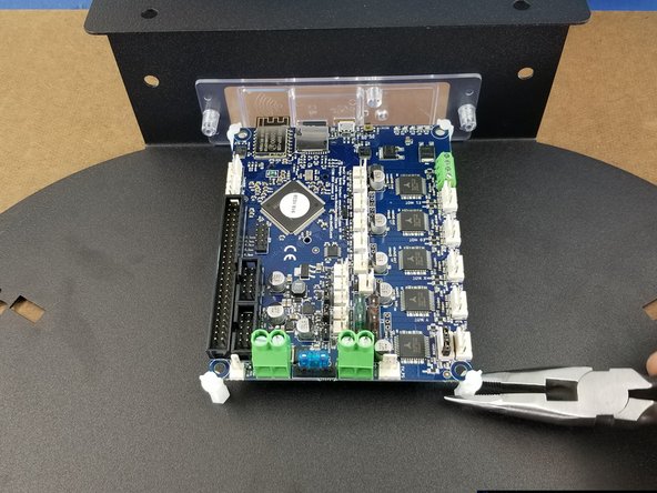
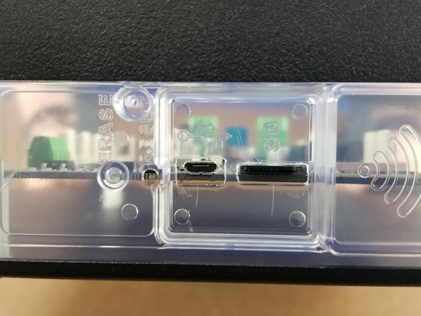
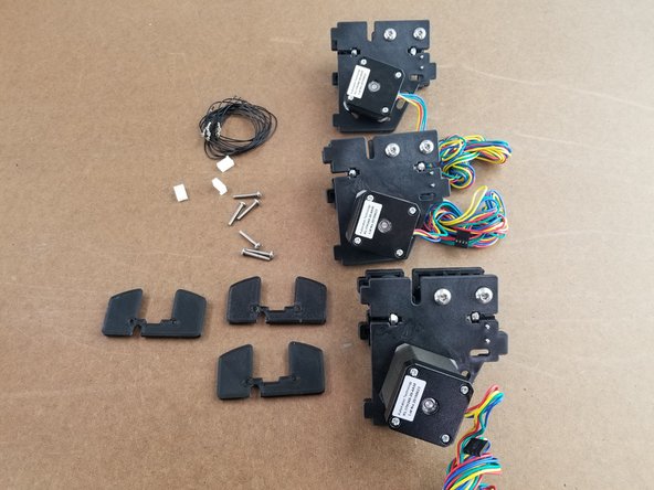
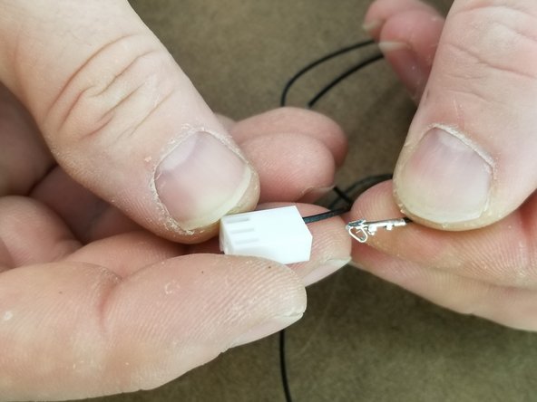
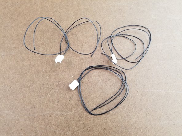
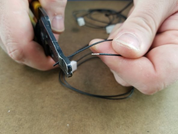
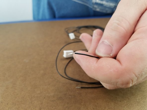
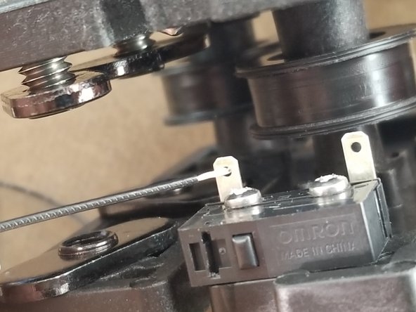
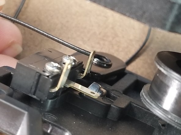
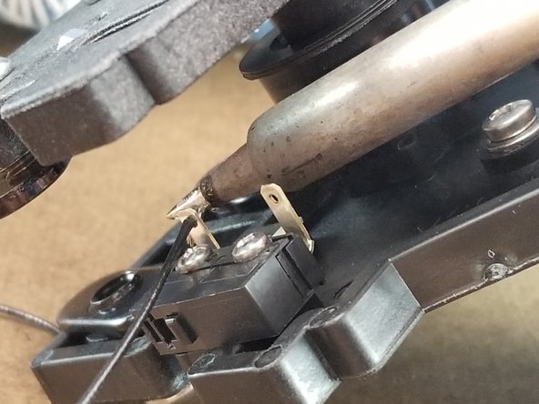
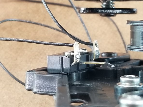
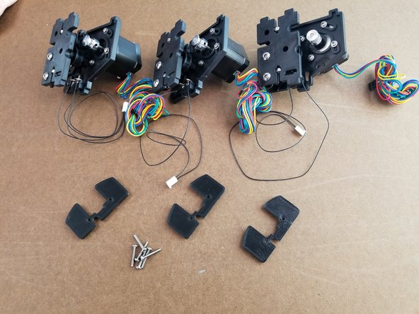
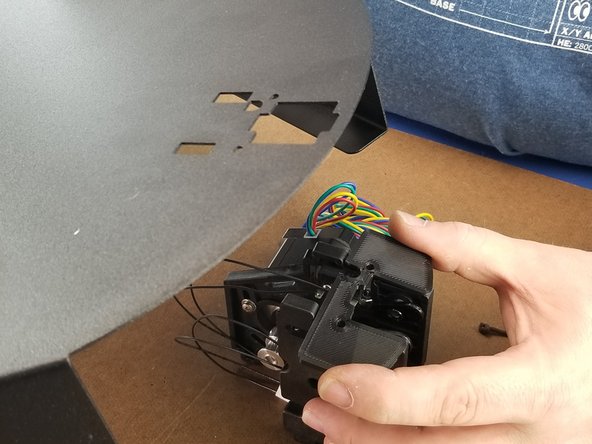
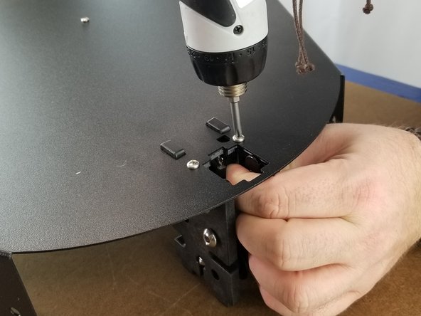
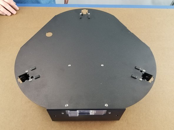
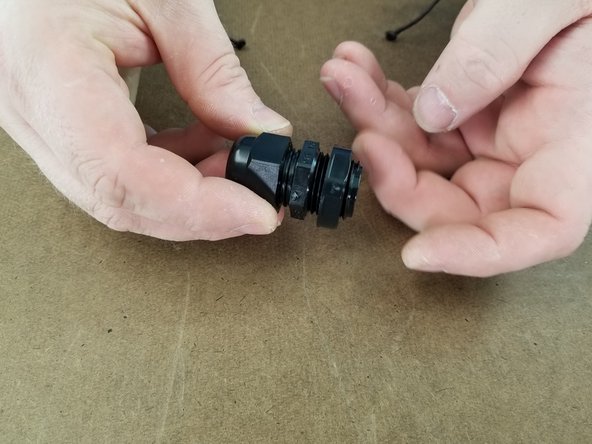
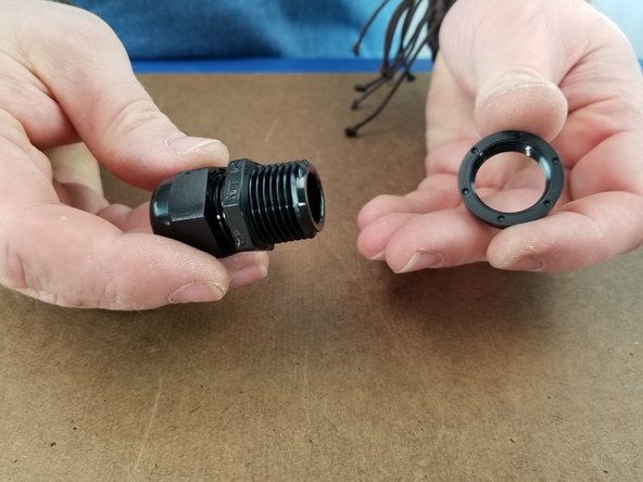
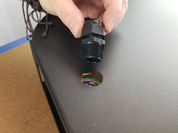
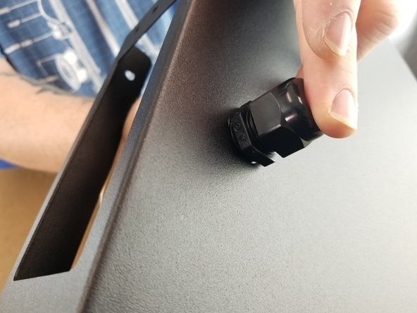
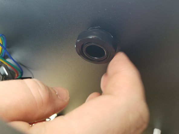
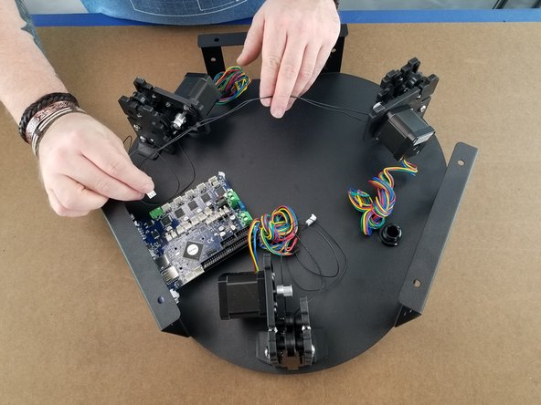
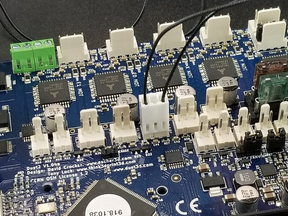
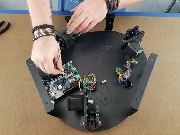
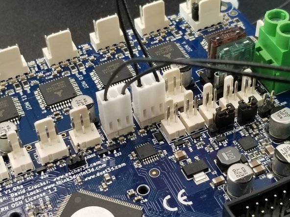
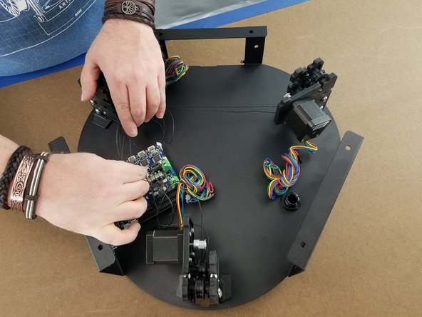
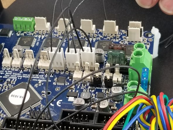
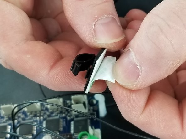
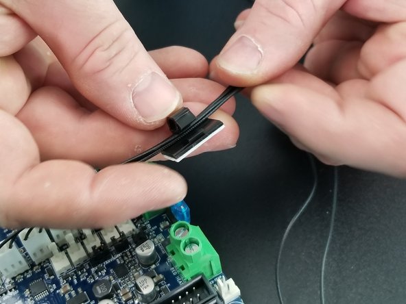
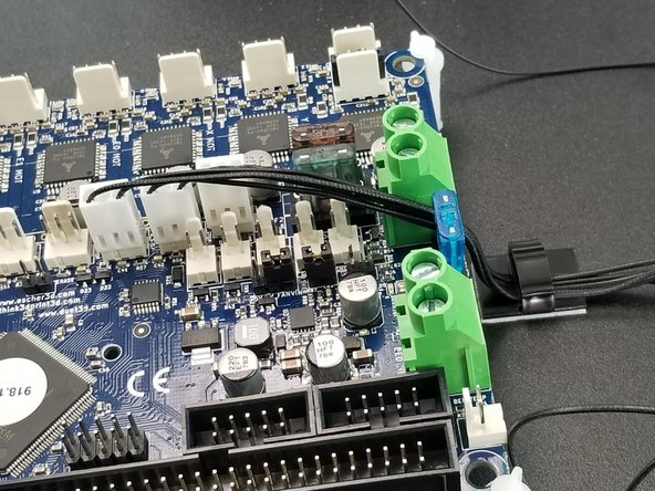
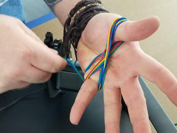
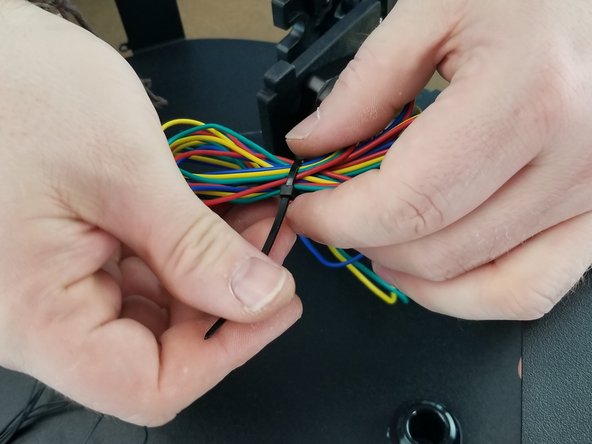
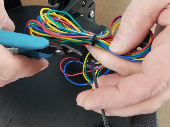
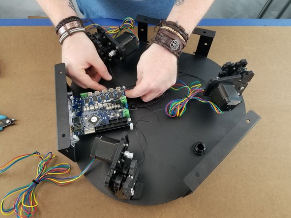
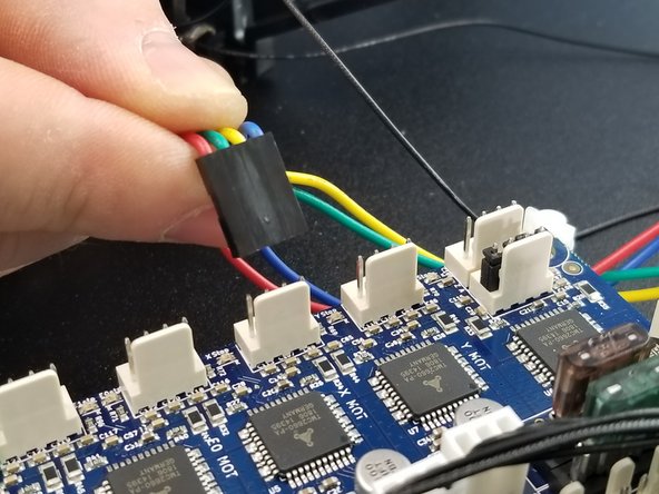
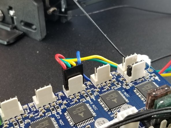
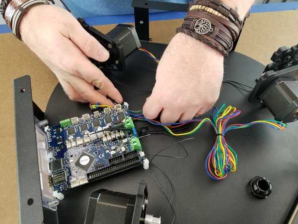
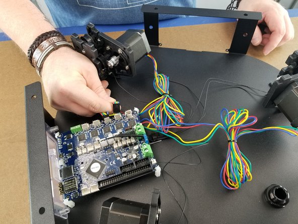
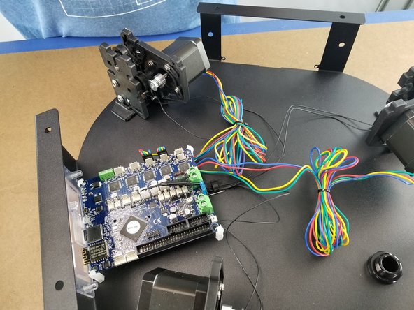
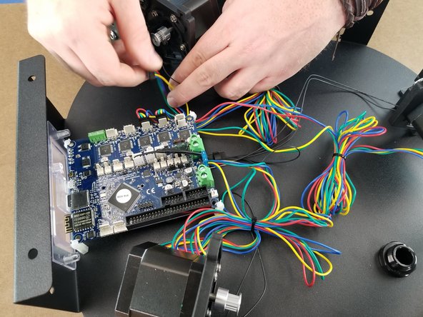
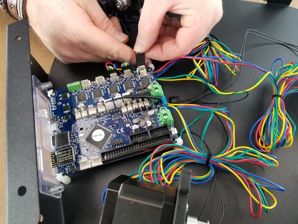
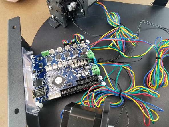
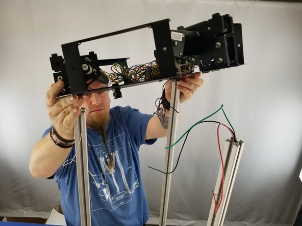
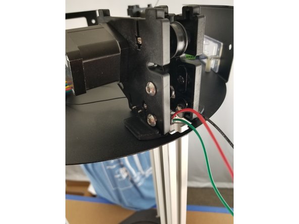
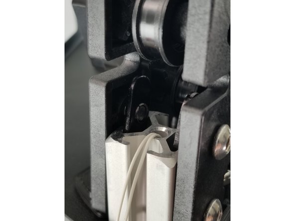
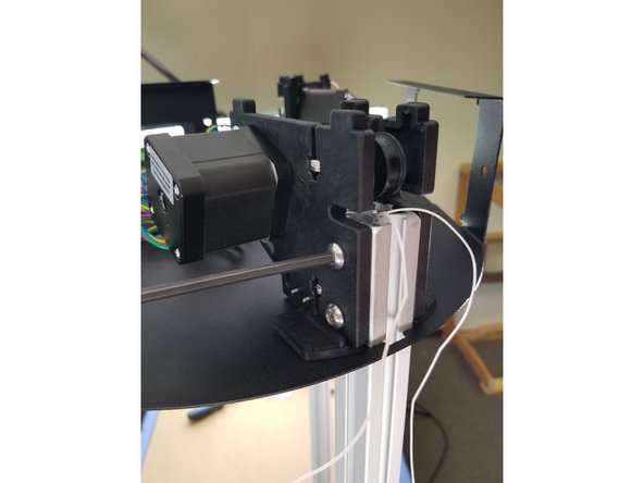
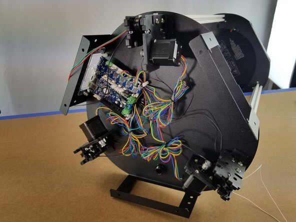
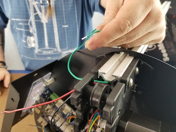
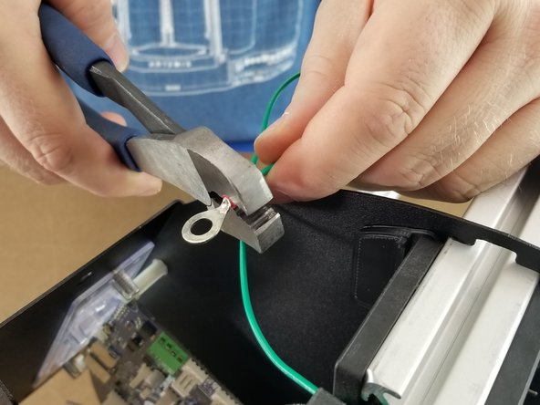
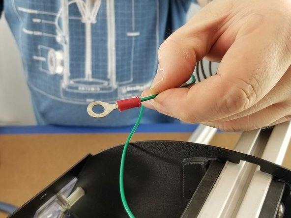
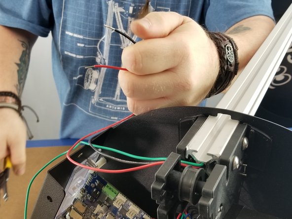
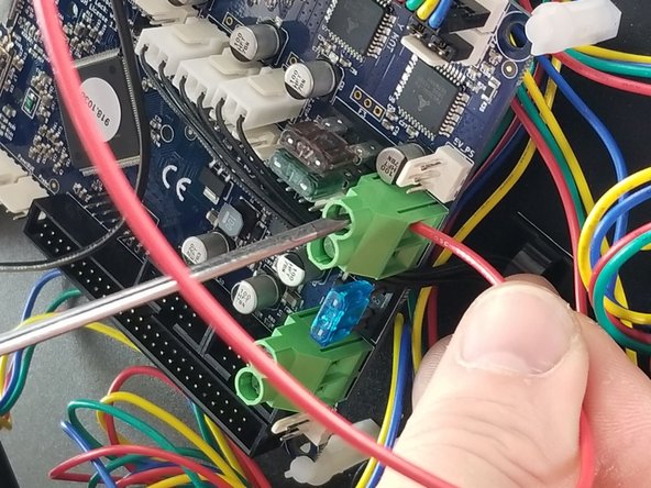
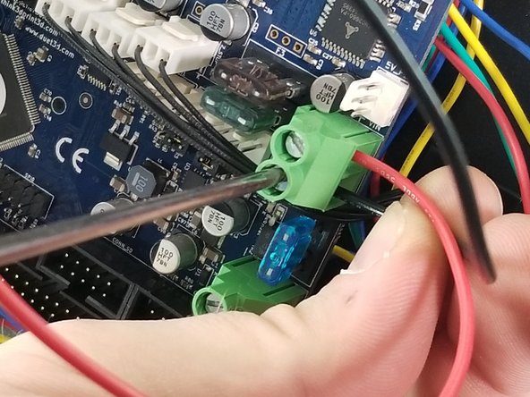
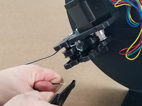
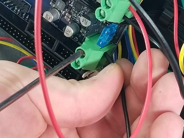
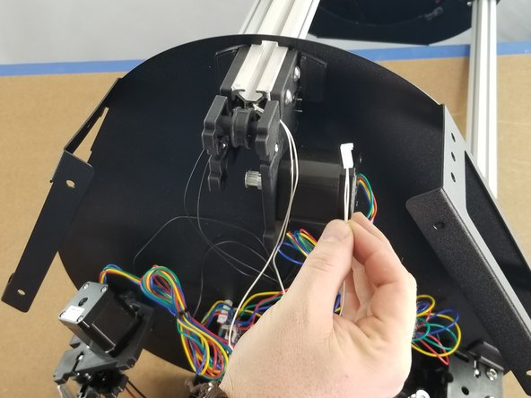
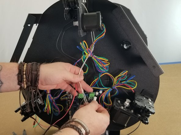
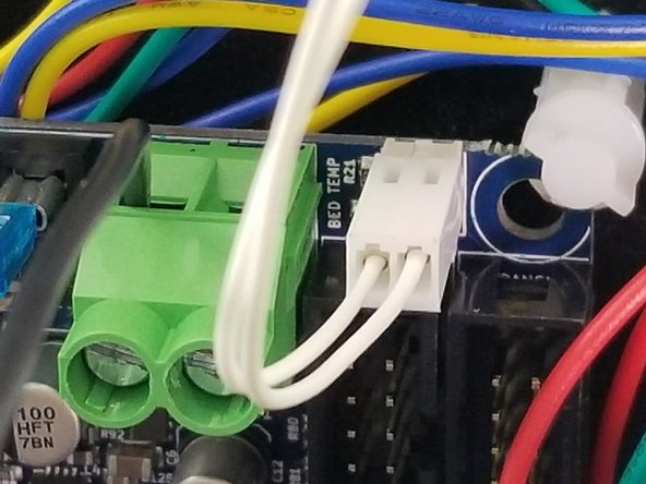
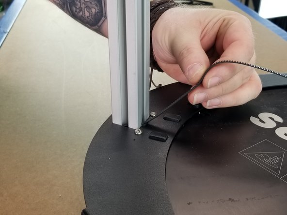
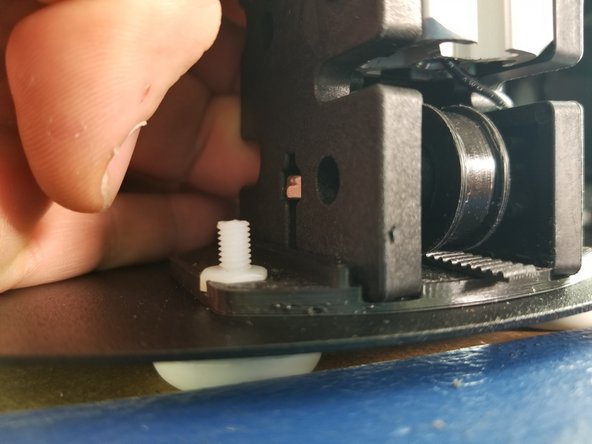
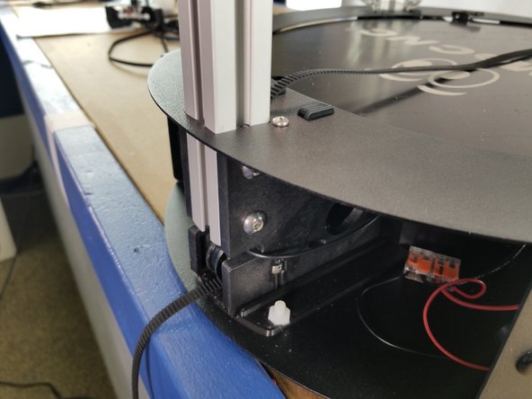
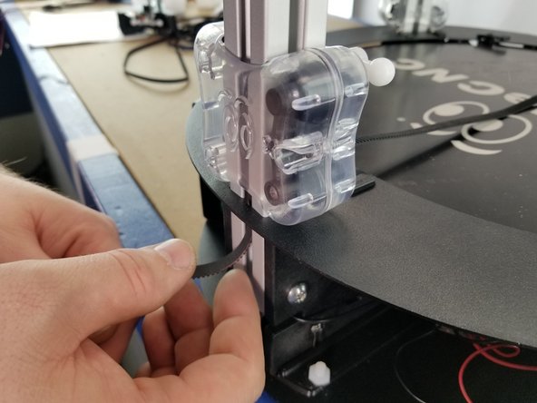
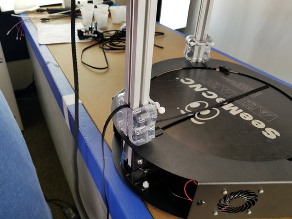
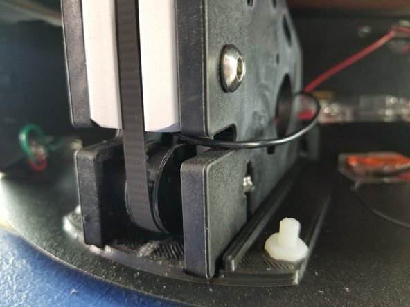
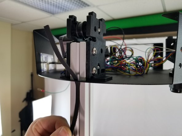
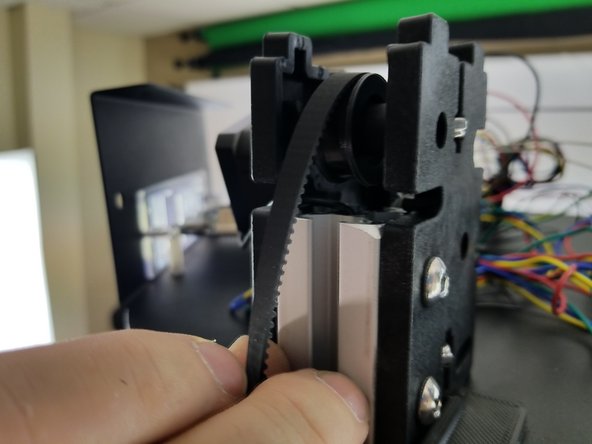
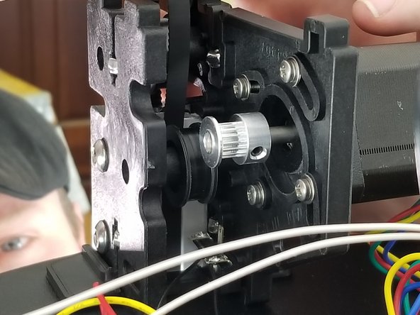
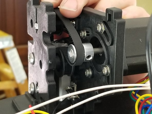
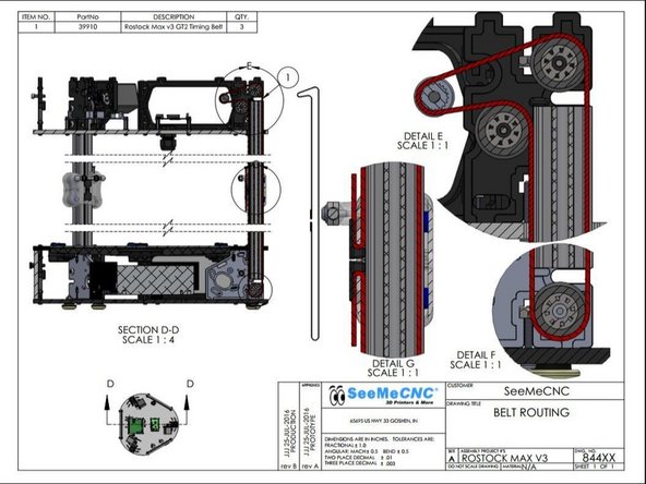
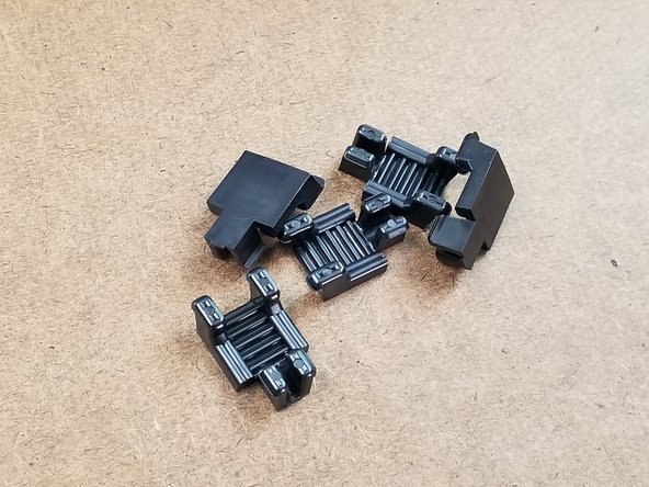
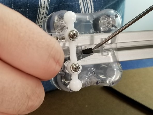
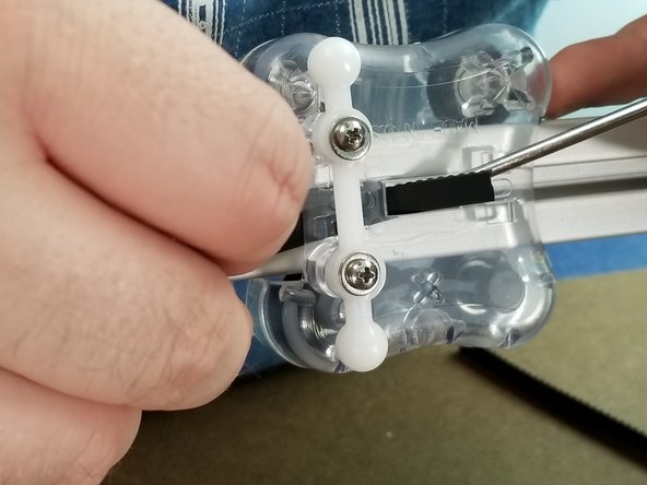
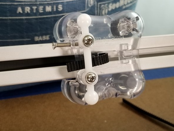
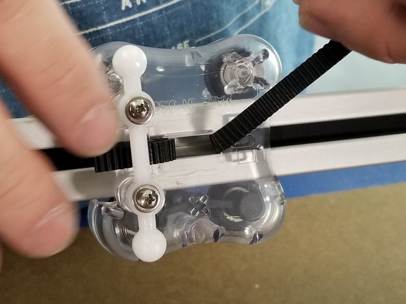
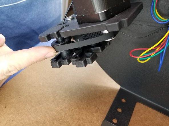
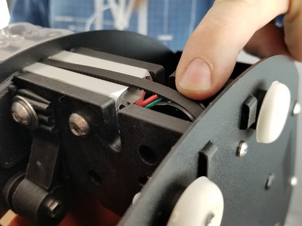
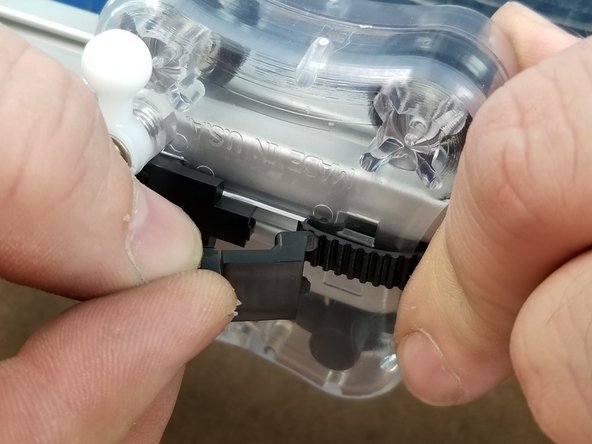
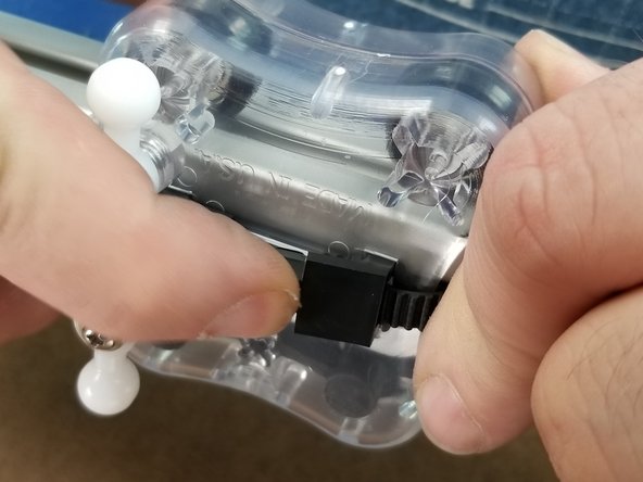
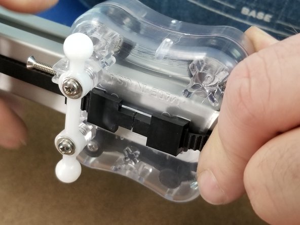
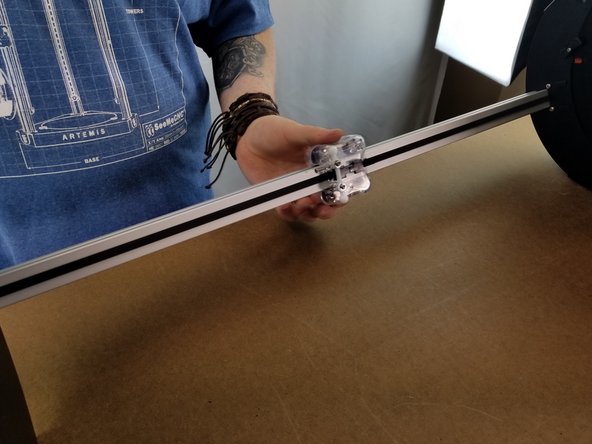
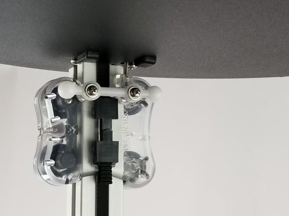
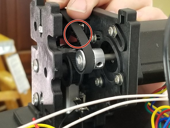
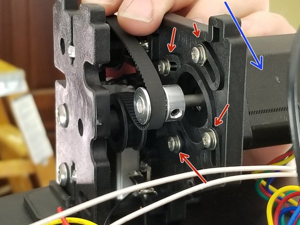
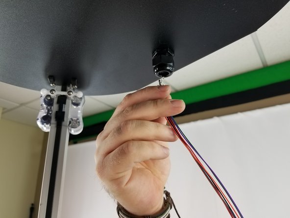
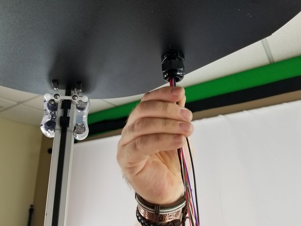
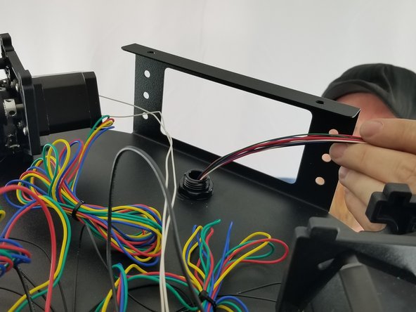
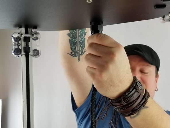
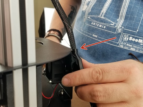
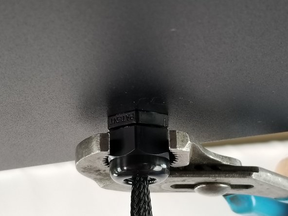
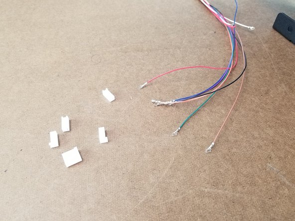
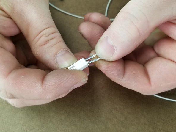
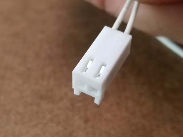
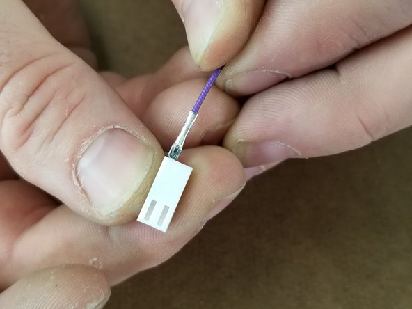
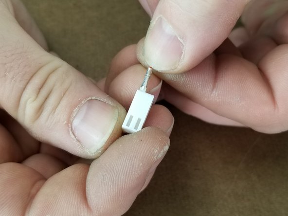
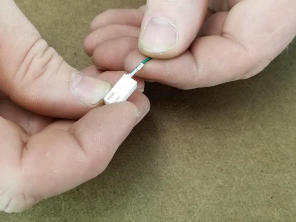
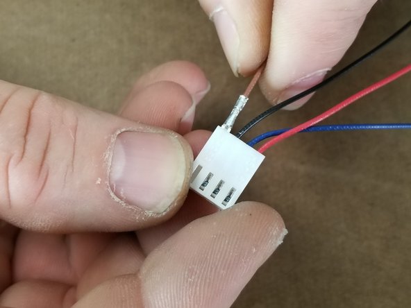
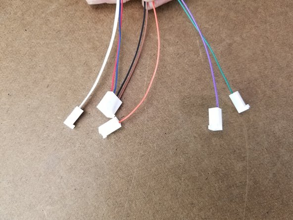
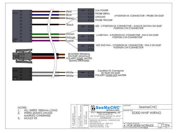
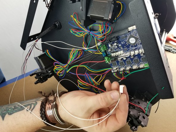
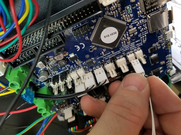
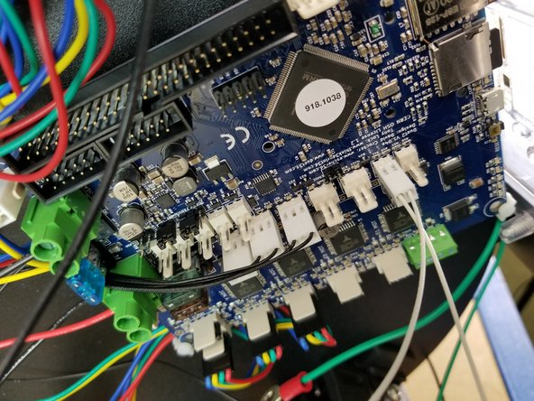
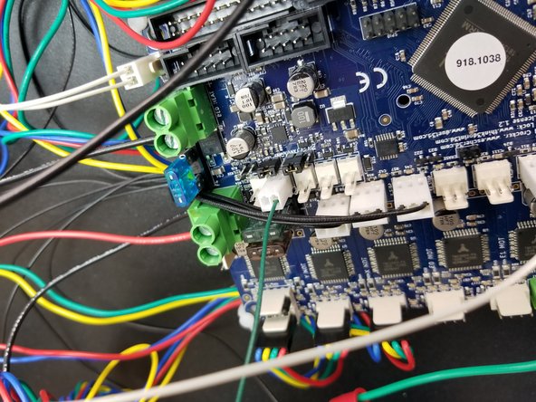
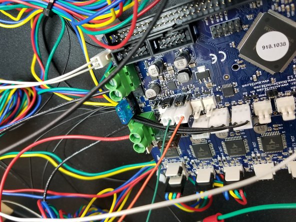
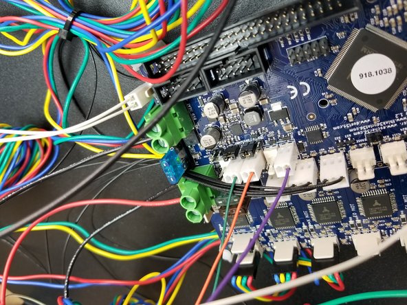
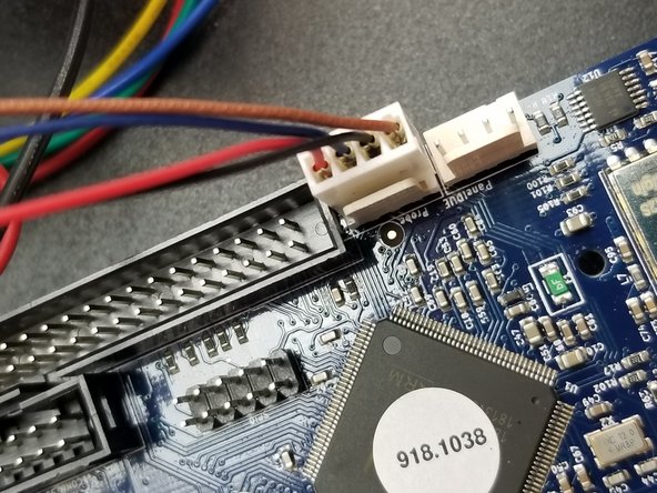
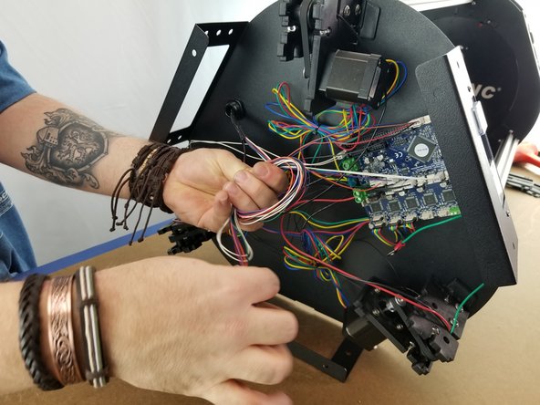
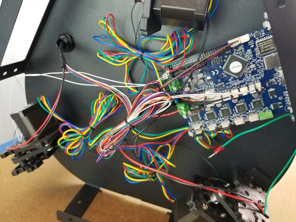
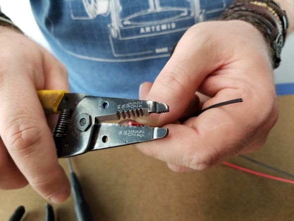
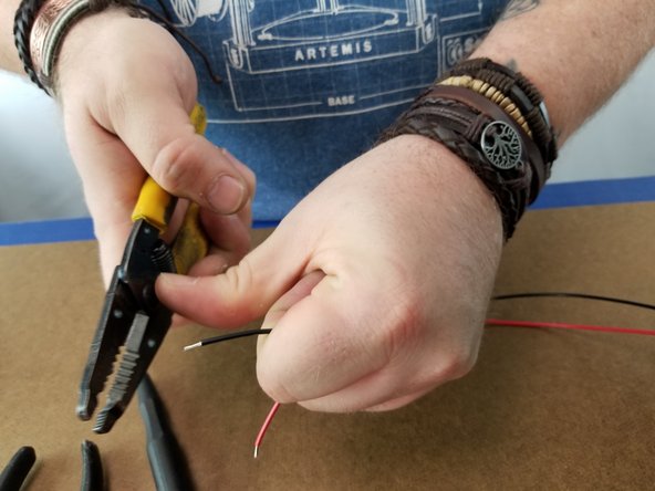
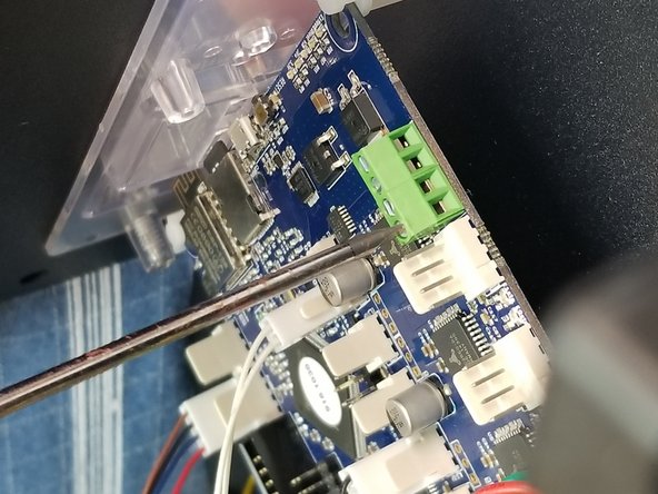
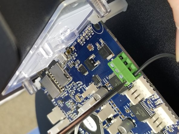
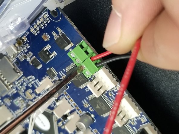
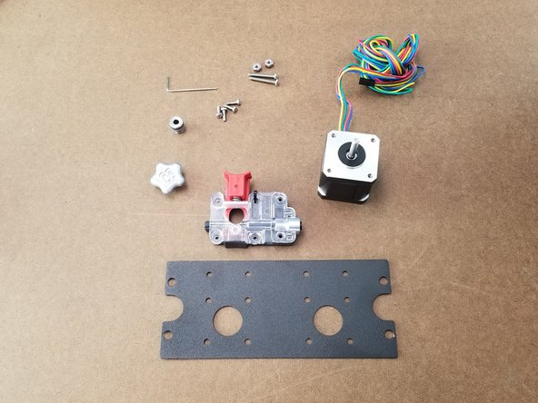
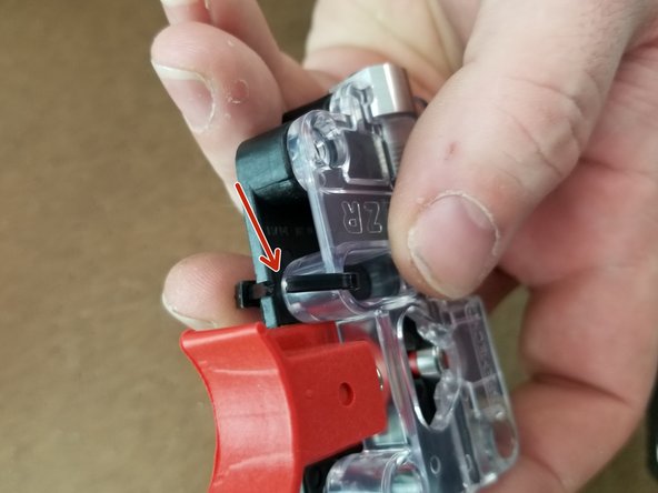
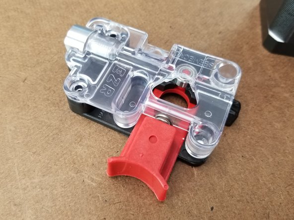
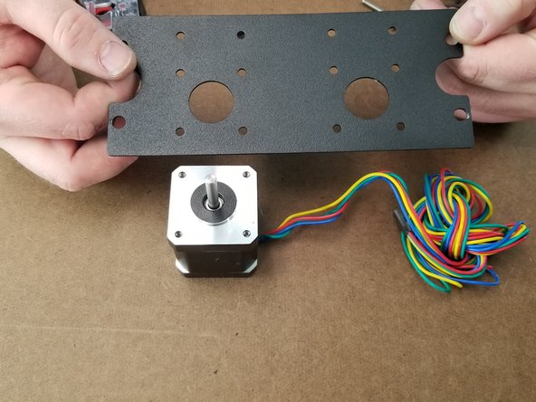
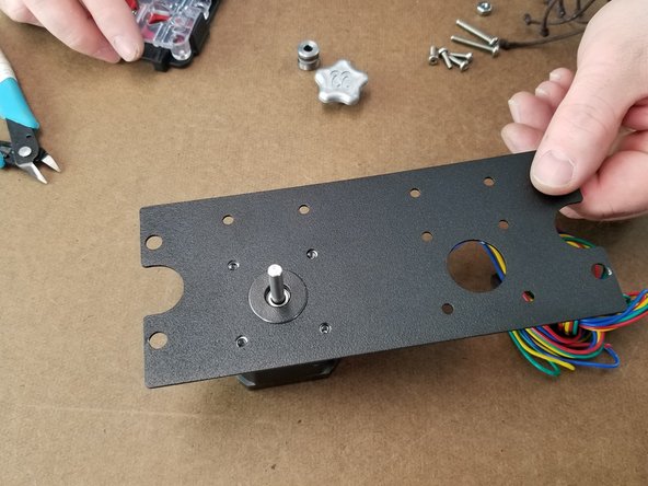
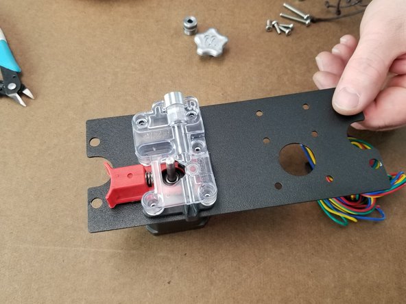
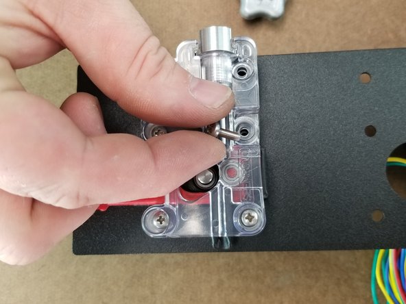
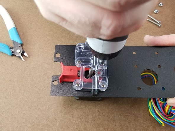
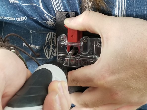
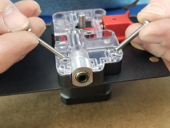
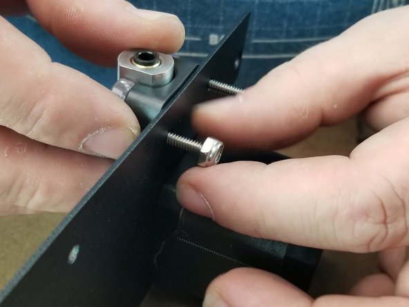
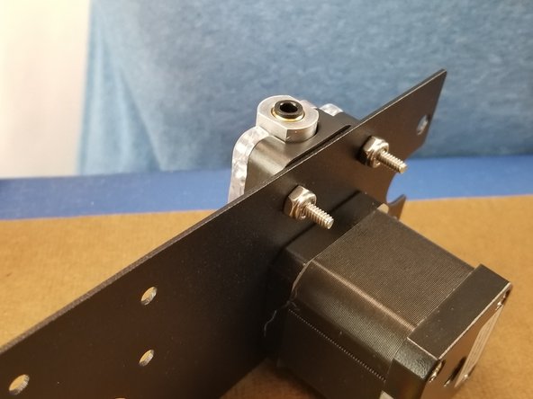
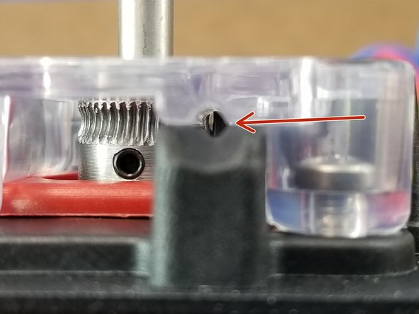
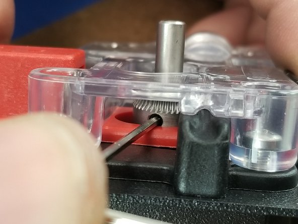
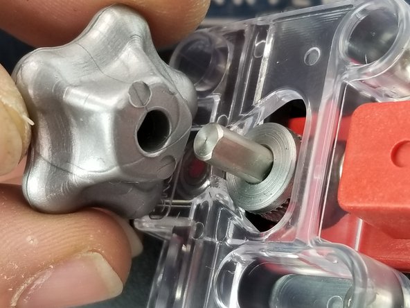
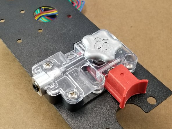
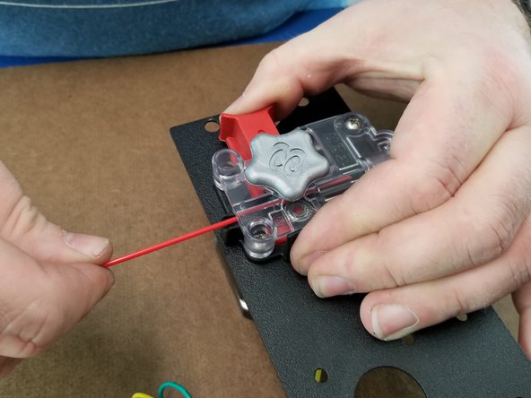
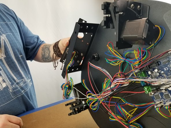
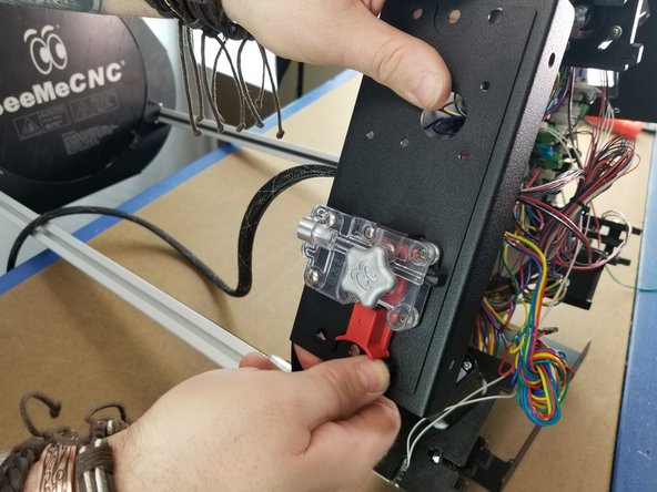
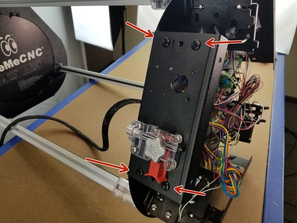
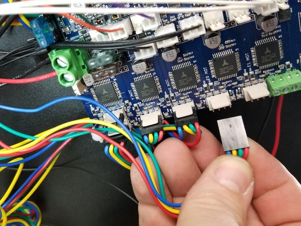
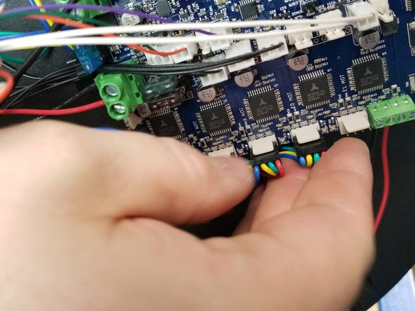
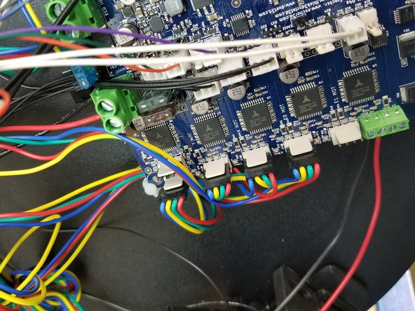
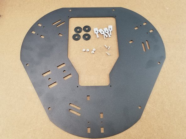
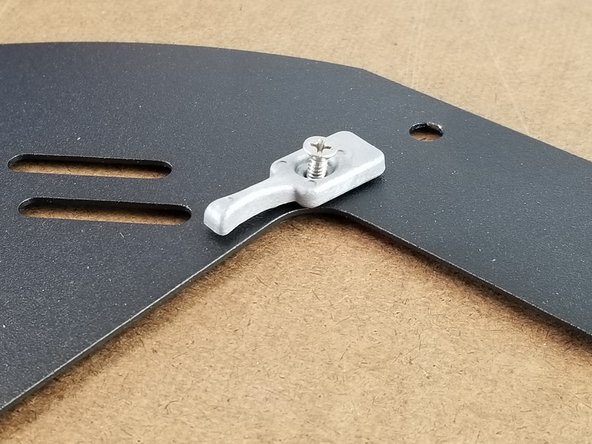
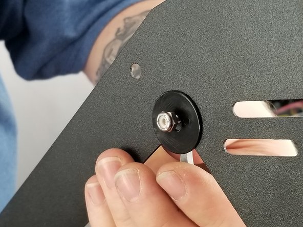
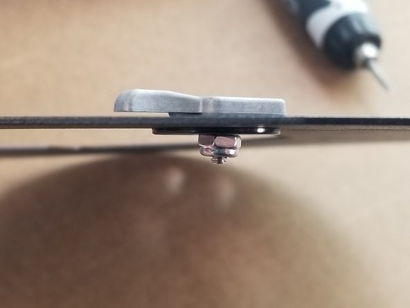
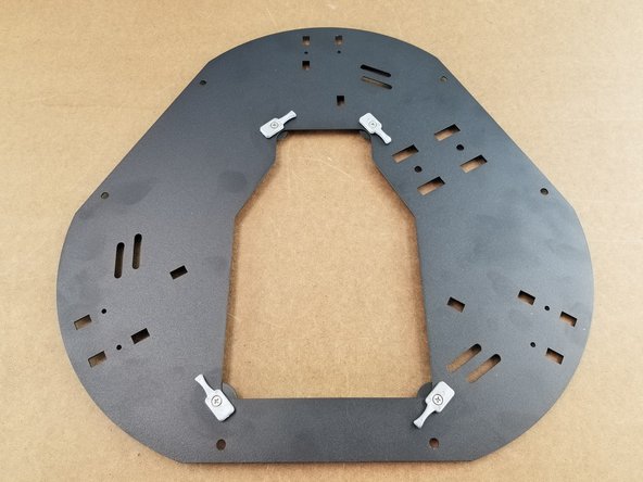
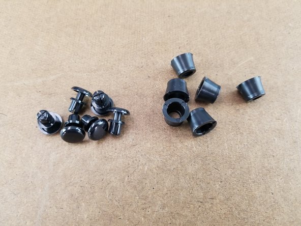
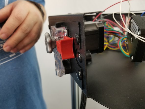
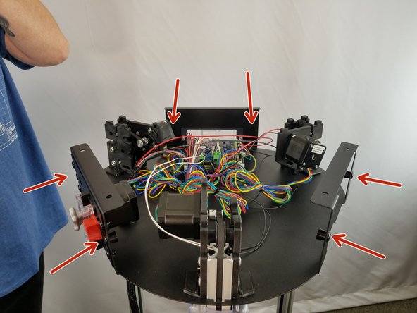
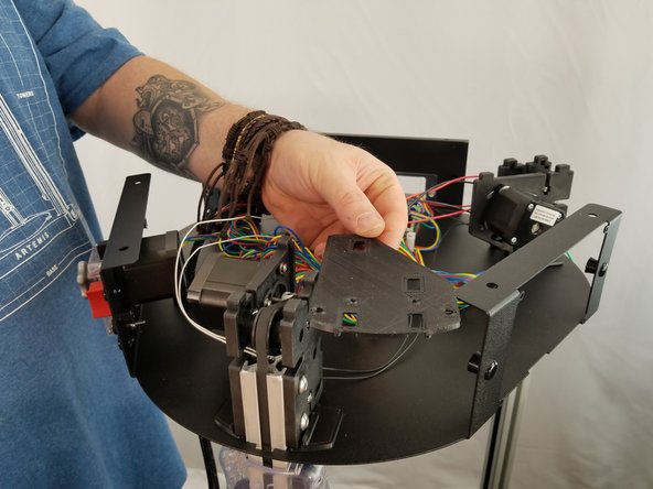
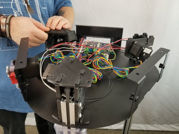
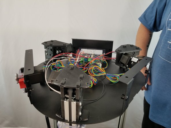
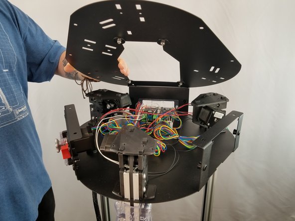
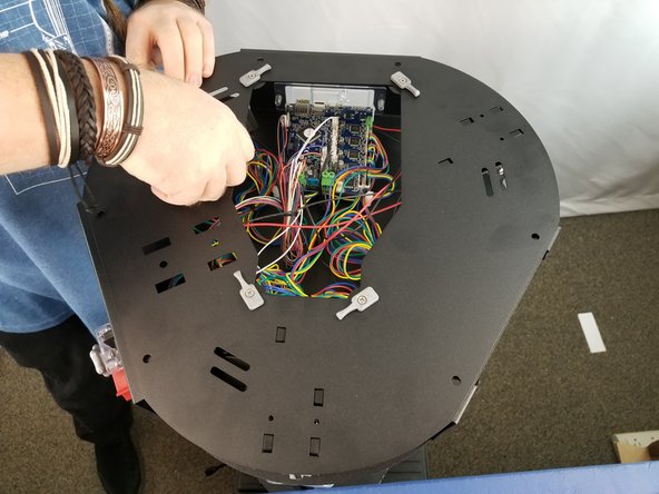
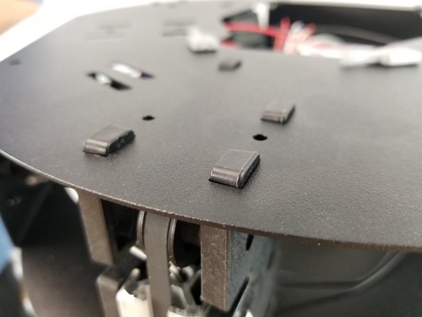
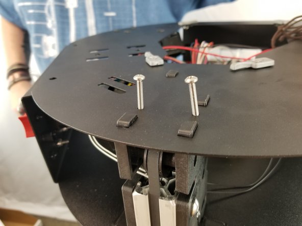
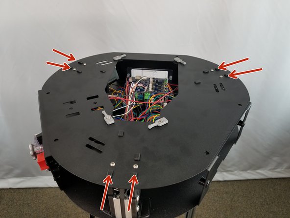
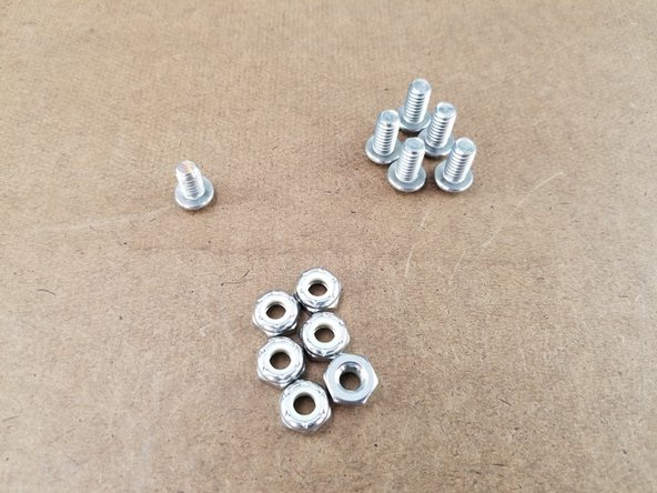
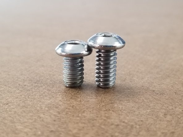
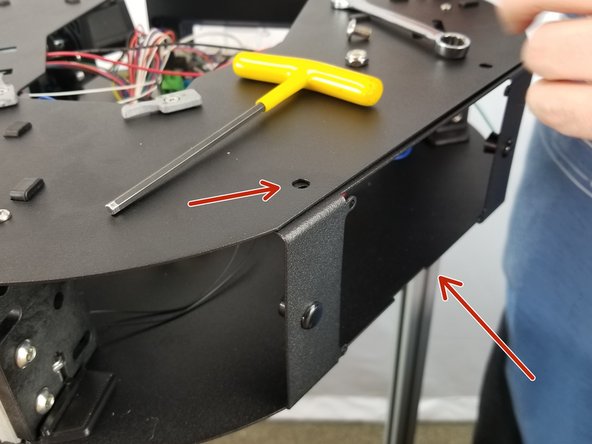
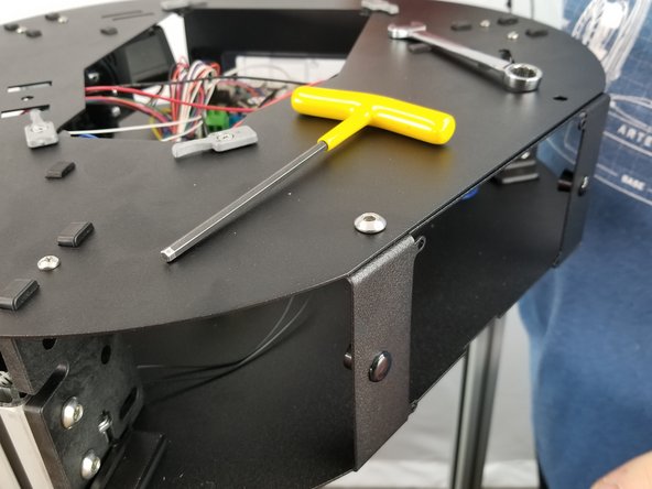
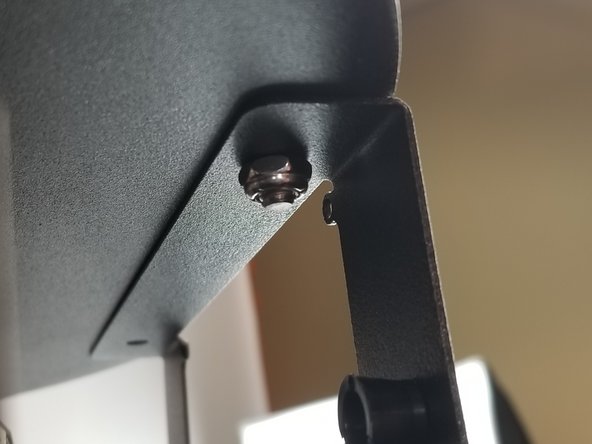
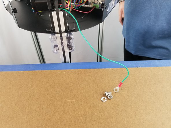
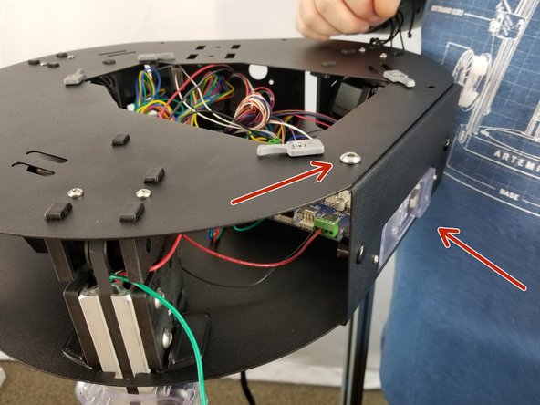
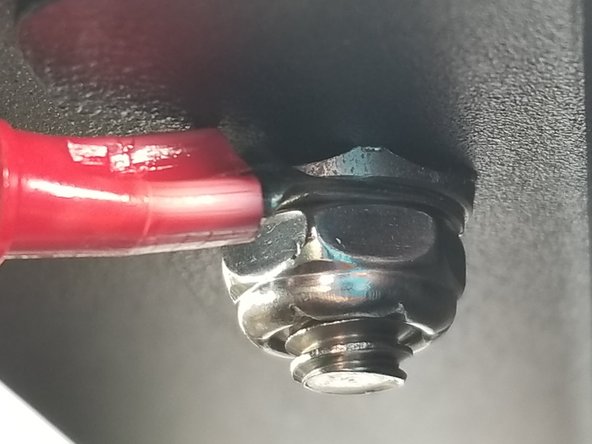
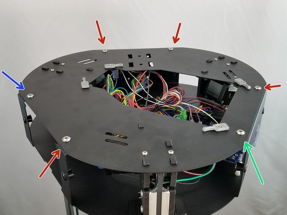
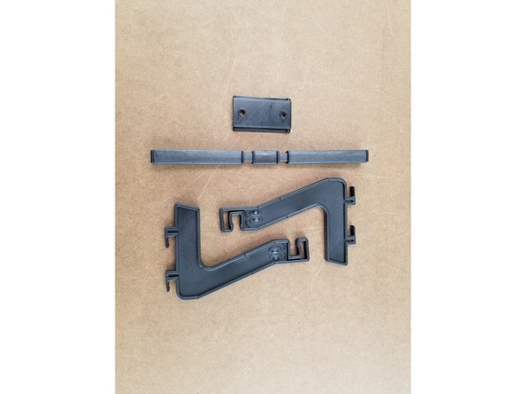
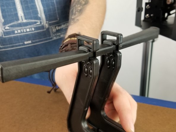
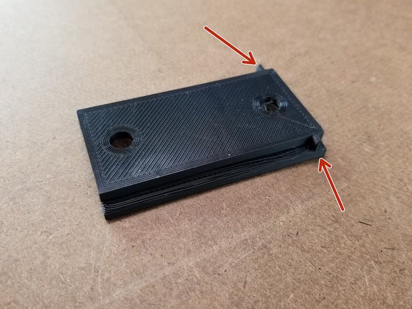
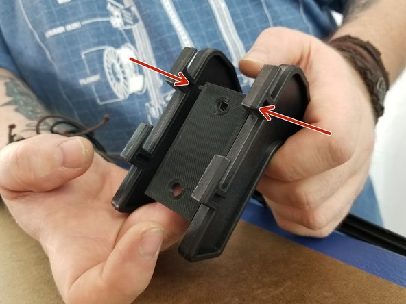
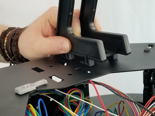
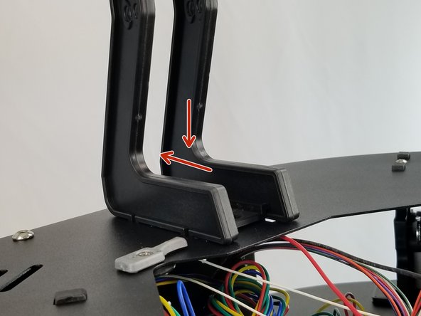
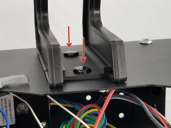
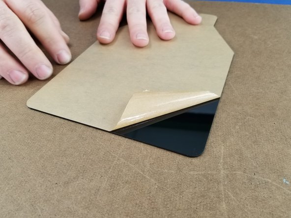
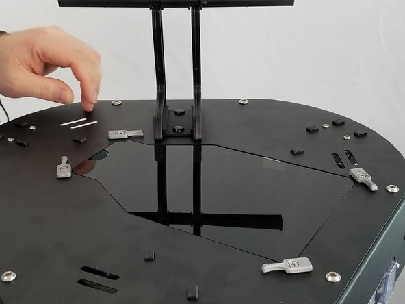
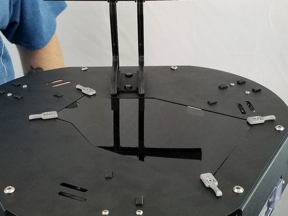
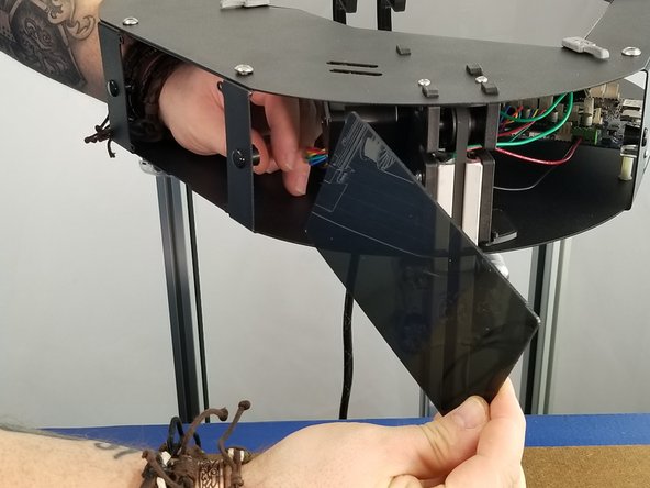
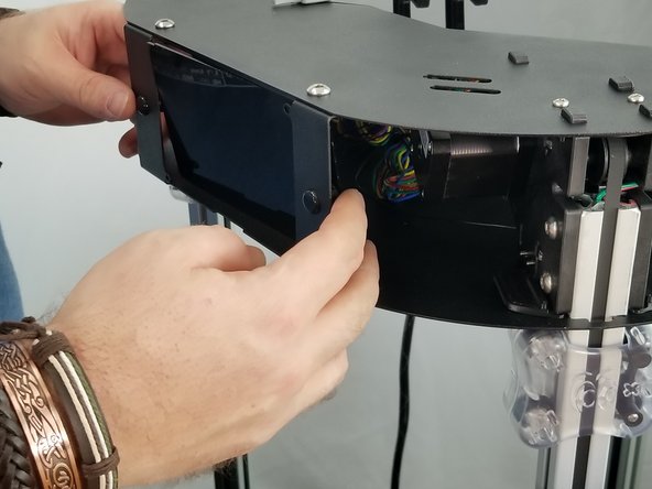
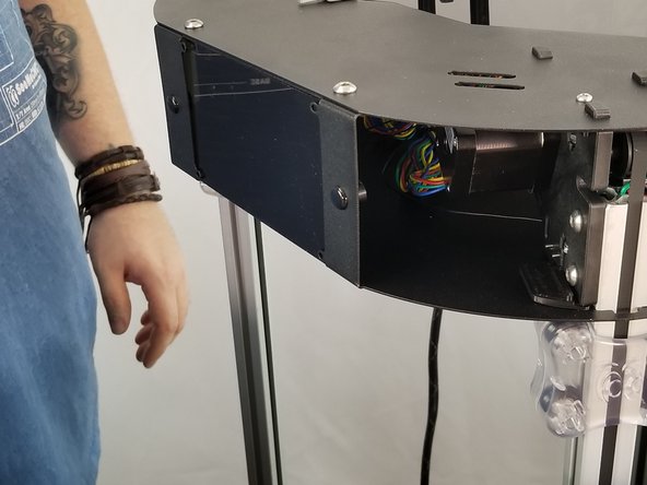
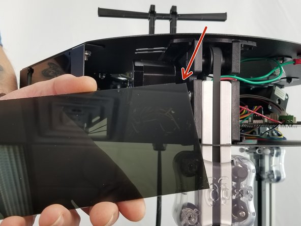
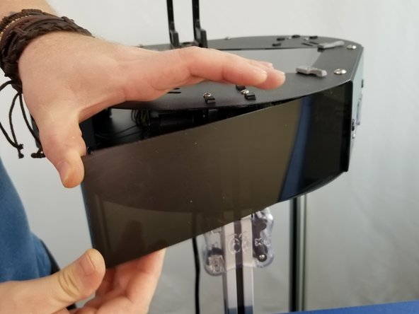
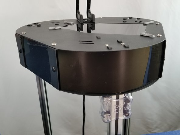
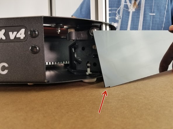
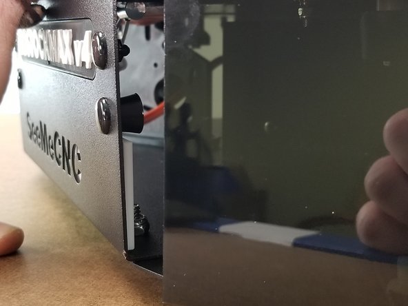
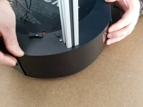
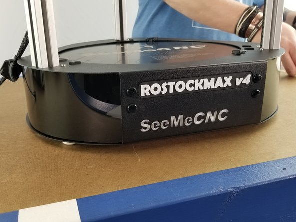
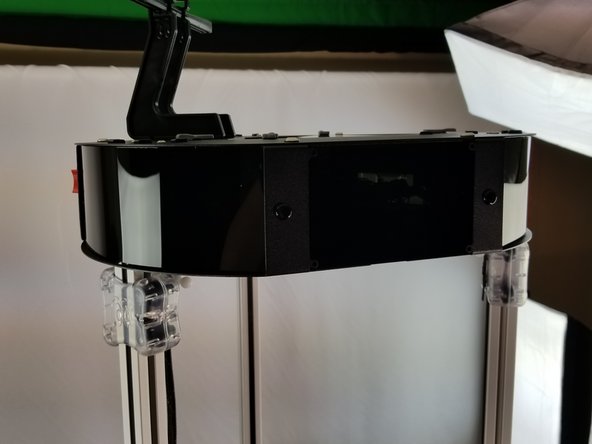
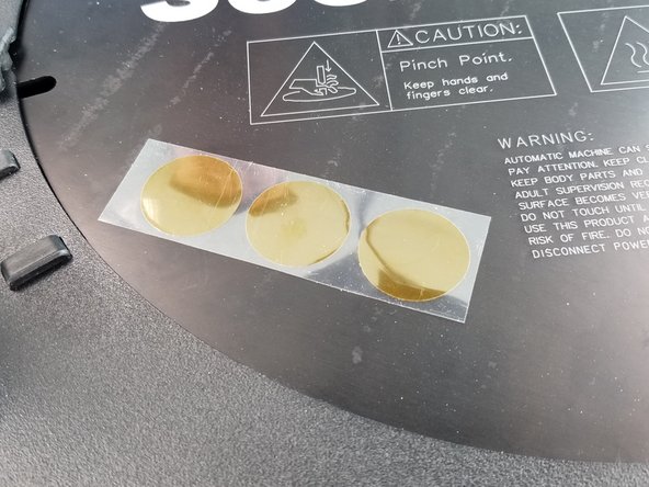
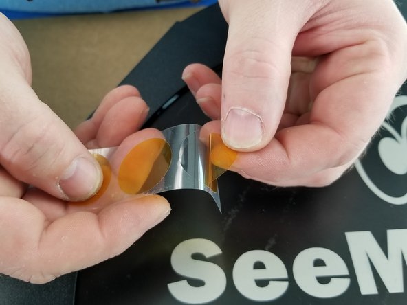
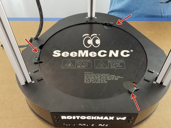
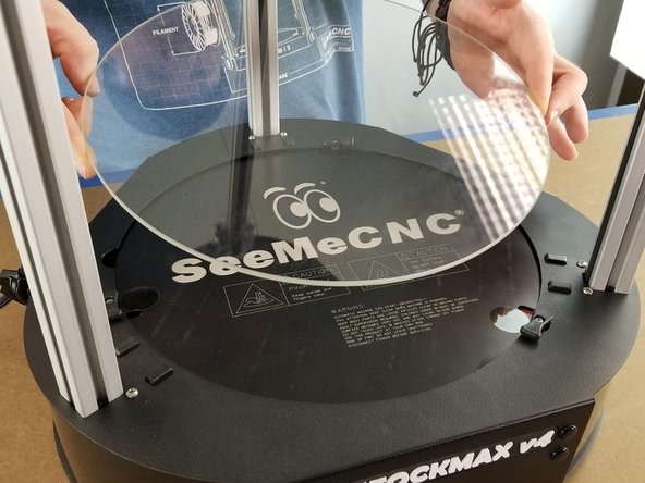
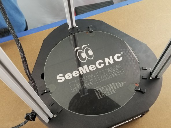
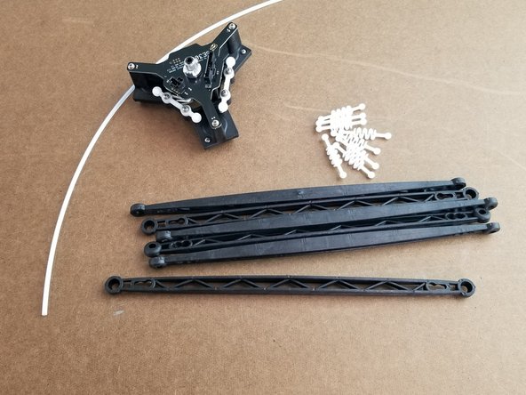
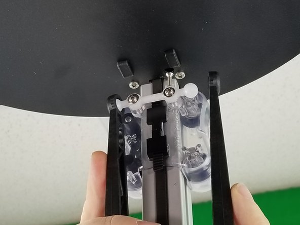
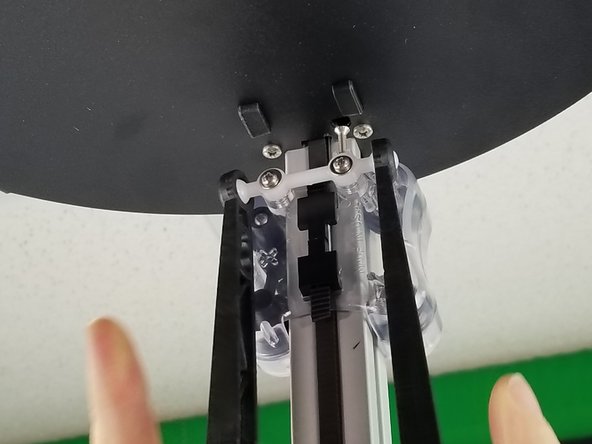
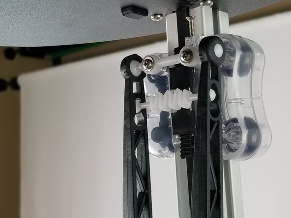
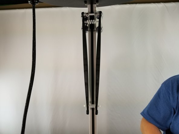
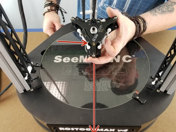
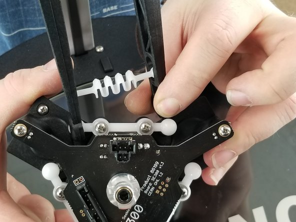
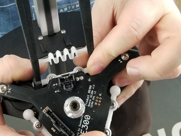
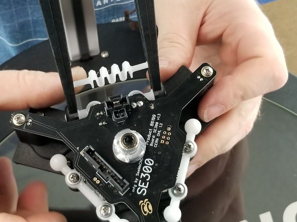
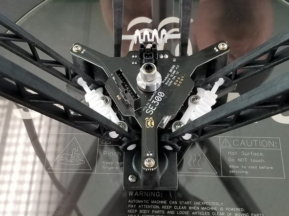
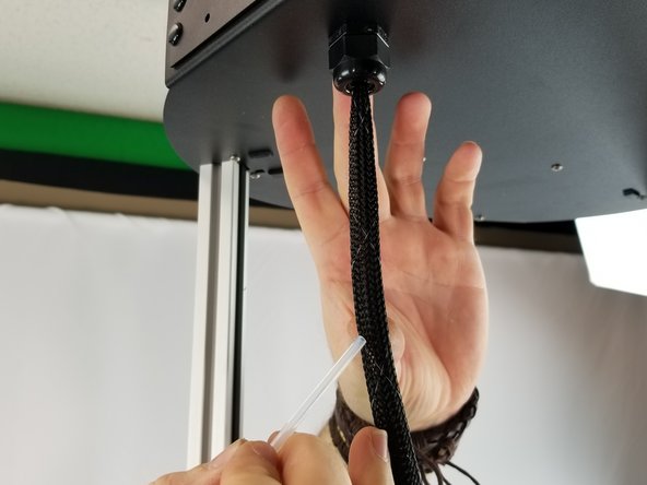
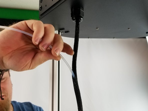
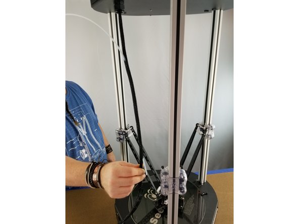
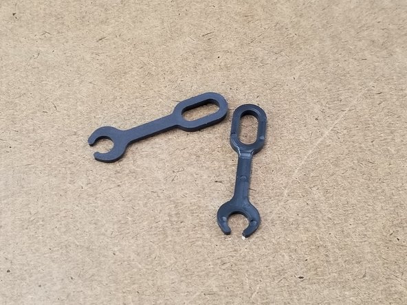
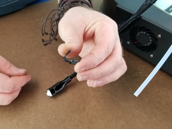
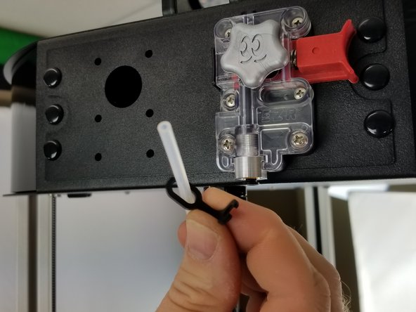
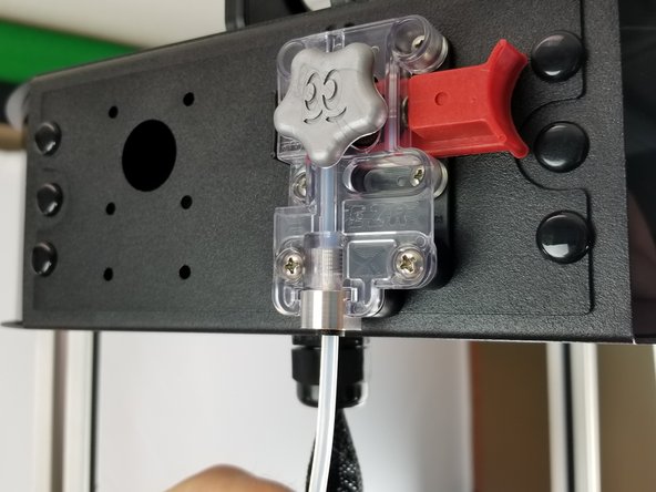
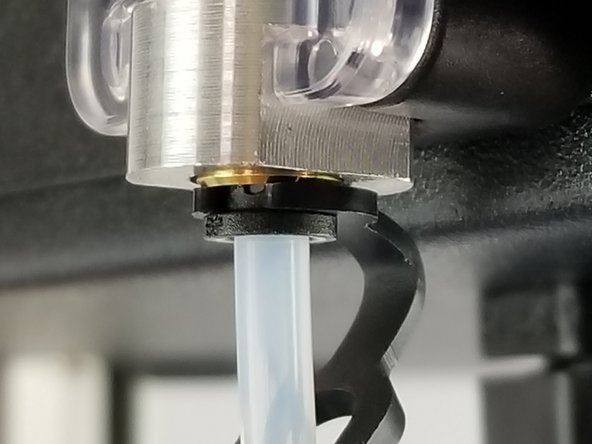
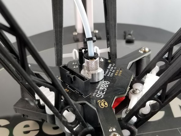
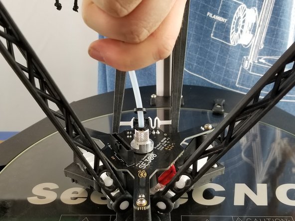
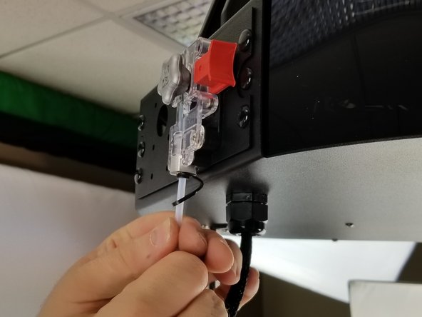
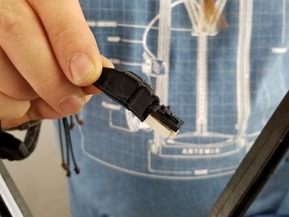
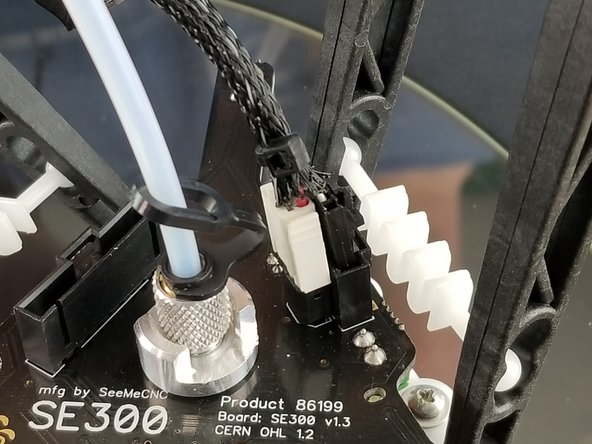
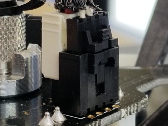
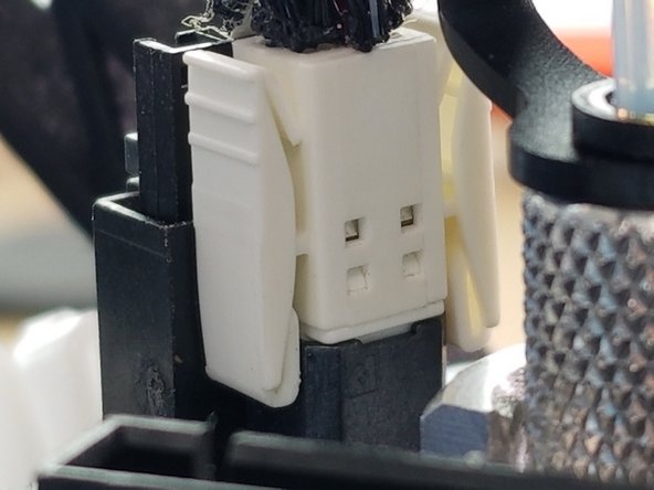
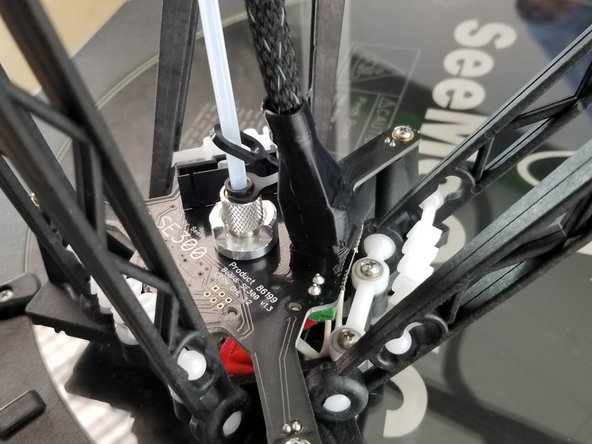
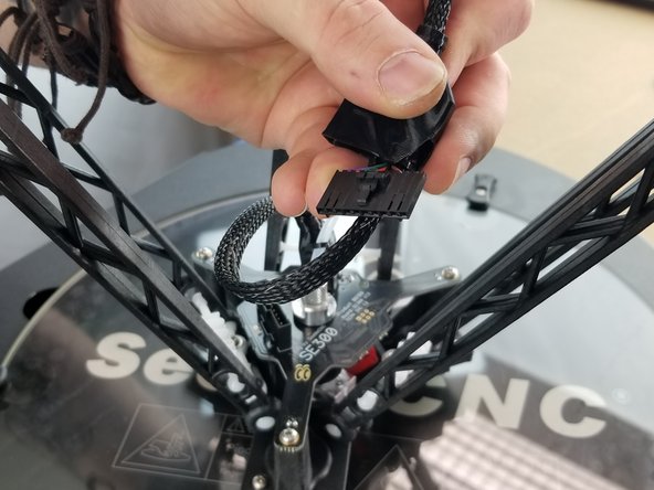
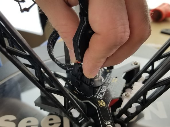
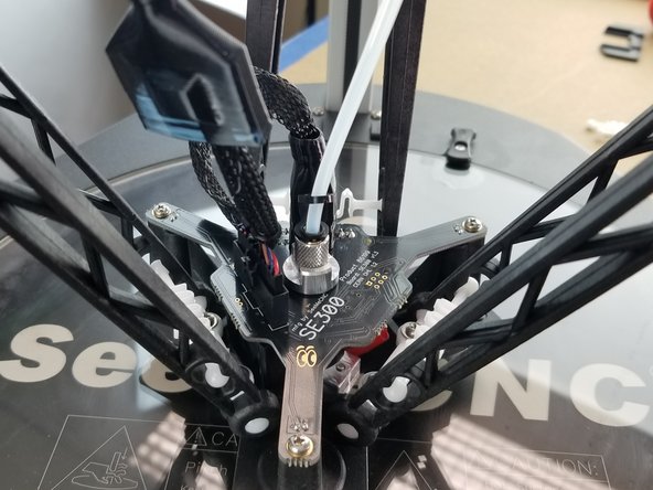
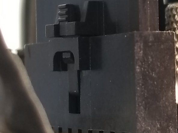
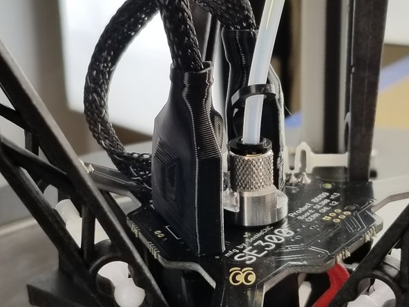
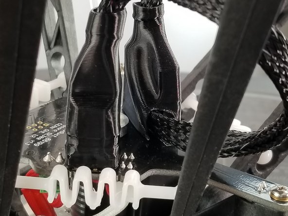
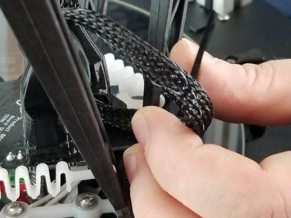
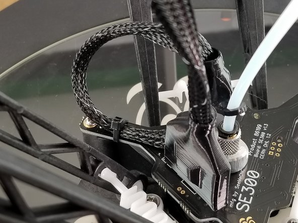
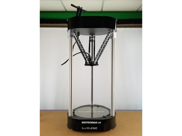
Cancel: I did not complete this guide.
8 other people completed this guide.
Attached Documents
