
Difficulty
Moderate
Steps
59
Time Required
- HE280 Assembly 59 steps

User-Contributed Guide
This guide is not managed by the site's staff.
Quiz
0
Tools
- Phillips Screwdriver, size P1
- small flat blade screwdriver
- 1/4" or 6mm wrench
- 5/16" or 8mm wrench
- 5/8" or 15mm wrench
- needle nose pliers
- cigarette lighter
- 2" of Scotch tape
- small wire cutters
- wire stripper for ~26G wire
- soldering iron and solder
- scissors or hobby knife
- Crescent wrenches × 2
- Tape Measure
Parts
No parts specified.
-
-
Please thoroughly read the Introduction - Read Me First
-
Want to download this guide as a PDF? Click on the PDF link just above the image and save as PDF
-
-
-
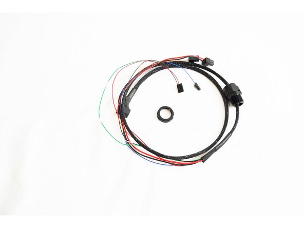
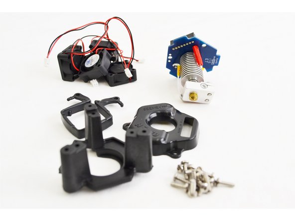
Locate the parts that will be used to assemble your HE280 whip. They are part of the hardware pack 84490 which can be found in the final assembly hardware packs.
-
NOTE: The 2 position terminal blocks (used for this assembly) that connect to Heat 0, Fan 0 and Heat 2 - BED are located in the RAMBo box in a ziplock bag.
-
This is a good video. But I would suggest using a straight coat hanger as a snake. Insert it on one end of the loom, then tape the wire bundle to it, and gently pull the hanger out.
Robert Maio - Resolved on Release Reply
-
-
-
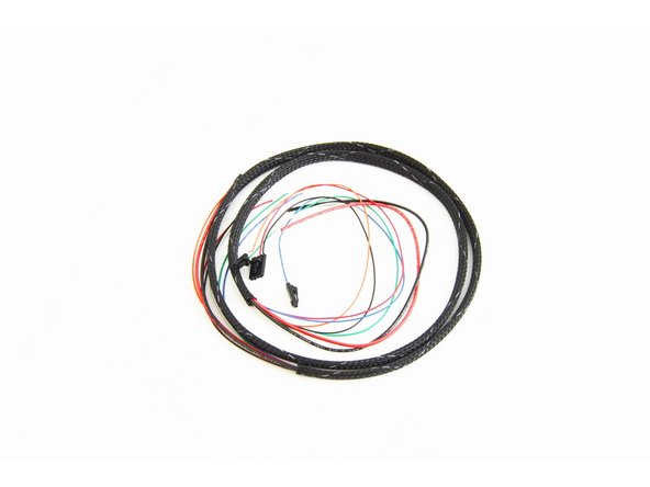
Use a bit of tape to group the wire ends together (on the end without connectors) in order to make it easier to route through the mesh loom.
-
Insert the mesh loom over the end of the wires that you just taped.
-
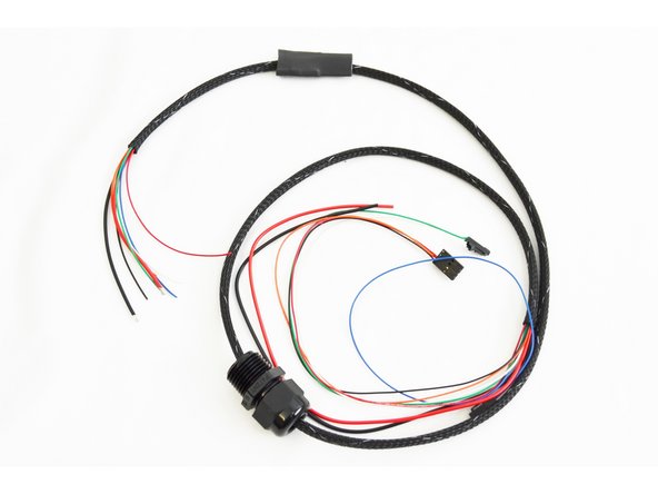
Feed the wires all the way through the mesh loom.
-
The picture shows this step complete.
-
-
-
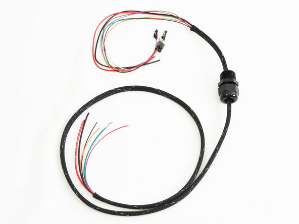
Insert the cable mount hub (26220) onto the wire bundle.
-
Note the orientation of the cable mount hub. The threaded side of this fitting should be closest to the ends of the wires that have connectors pre-installed.
-
-
-
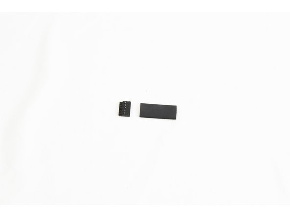
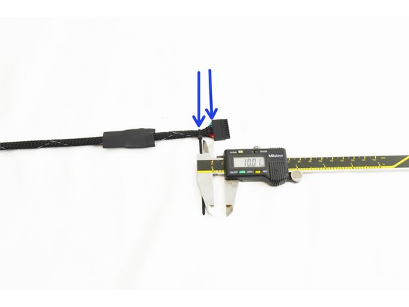
To prepare the heat shrink tubing (84431), one side needs to be stretched enough to fit over the end of the Pluggable 8 position Push-In Wire Terminal Plug End (26217)
-
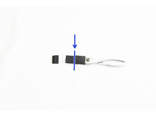
The easiest way to do this is to use a pair of pliers (fully closed) inserted half way into the heat shrink,
-
When performing this step, be sure to not to over-stretch the heat shrink tubing causing rips or tears.
-
Proceed to slowly open the pliers to stretch the heat shrink.
-
This process may require stretching a shorter section, inserting the pliers further, and then stretching that section.
-
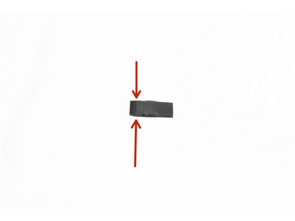
Test fit the heat shrink tubing over the end of the Pluggable 8 position Push-In Wire Terminal Plug End. You can see in the pic, the proper depth to have the plug inserted into the heat shrink.
-
-
-
Insert the heat shrink tubing that you stretched in the previous step onto the whip. The stretched out portion should be facing the end of the whip without any terminated wires.
-
Next, you will insert the wires (from the end of the whip without any connectors) into the Pluggable 8 position Push-In Wire Terminal Plug End. The correct order of wires is shown here: HE280 Whip Diagram
-
It is critical that the wires are not frayed at the ends, and that you insert them into the correct locations in the Pluggable 8 position Push-In Wire Terminal Plug. The orange wire should be inserted into POSITION 1 in this plug (as noted on the HE280 Whip Diagram)
-
Insert the wires one at a time. The preferred method is to use needle nose pliers to grasp the wire approximately 5mm from the end of the insulation and use the wires to push the end of the wire into the plug. Grasp the wire again approximately 5mm from the plug and push the wire in again. Repeat if necessary.
-
If you are having difficulty with the smaller gauge wires, you can depress the pin from the side of the connector, gently, with a flathead. While holding the flathead in place, insert the wire all the way into the connector, remove the flathead. The wire should go in easy and stay snuggly fit after the flathead is removed.
-
Give each wire a gentle push and pull to ensure that is securely seated in the plug. The move onto inserting the next wire until you have inserted all 8 wires.
Important! Each of the wires has the insulation at the end cut. Pull off the insulation and gently twist the strands for each wire before inserting. The video makes this clear. Note that the larger diameter wires (red & black) may feel like they're bottomed out when it is actually just the insulation caught on the side of the entryway--you may need to adjust them a bit to get the wires to go in further.
-
-
-
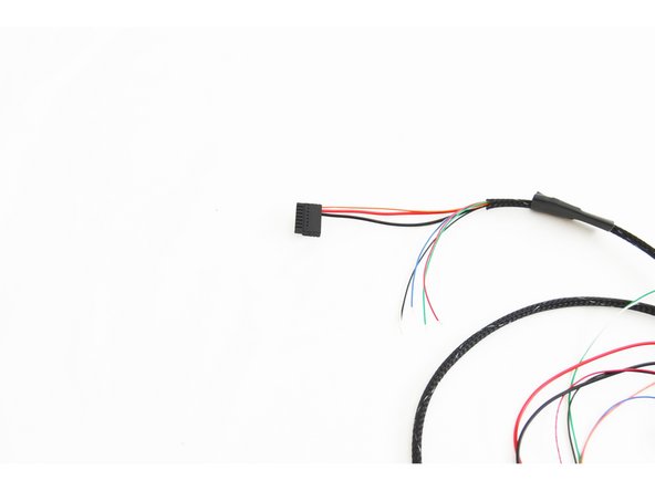
Slide the mesh loom down on the wires so it is approximately 5mm from the Pluggable 8 position Push-In Wire Terminal Plug.
-
Attach a Wire Tie (26164) over the mesh loom. Secure the wire tie approximately 10mm from the end of the Pluggable 8 position Push-In Wire Terminal Plug. Tighten securely.
-
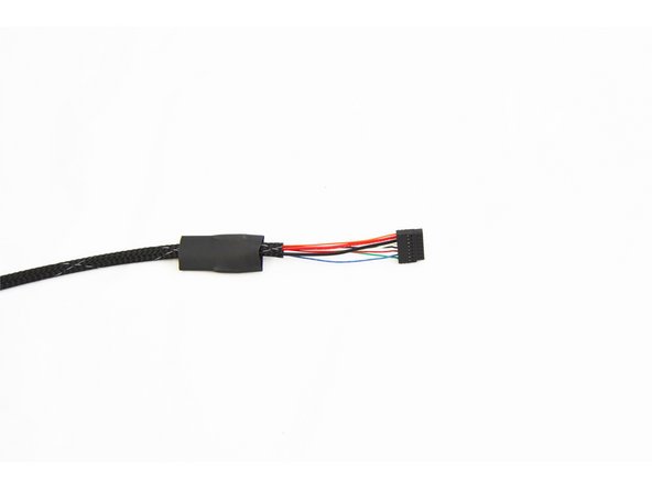
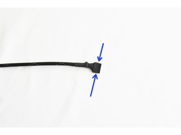
Slide the heat shrink tubing over the wire tie and Pluggable 8 position Push-In Wire Terminal Plug as shown in the pic. Apply heat to the heat shrink tube to secure it in place. Use your preferred instrument. (if using an open flame such as a lighter, be sure not to hold the flame too long in one spot, as this will char the heat shrink tube)
The second piece of heat shrink tubing magicaly appears in the last picture. It didn't do that on my whip.
Lukas Werner - Resolved on Release Reply
-
-
-
NOTE: This step is not performed for the H2 Delta printer or when upgrading Rostock Max v1/v2 or Orion Delta printers.
-
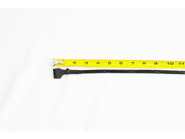
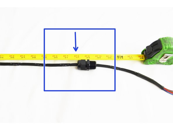
Measure 32" from the end of the whip with the Pluggable 8 position Push-In Wire Terminal Plug and make a mark on the mesh loom (Applying a piece of tape works well)
-
Align the Cable Mount Hub (26220) with the mark. (The reference is the opposite of the threads on the cable mount hub, as shown in the pic)
-
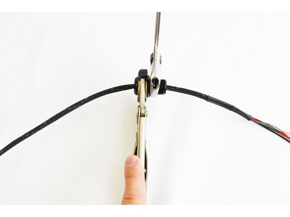
Use your available tools to tighten the hub securely to the loom. (For this example a crescent wrench and vise grip was used)
-
You will be tightening this fitting nearly 100%. It is designed in such a way that the teeth that grip the wires/loom will not cause any harm to the wires/loom.
-
-
-
NOTE: This step is not performed for the H2 Delta printer or when upgrading Rostock Max v1/v2 or Orion Delta printers.
-
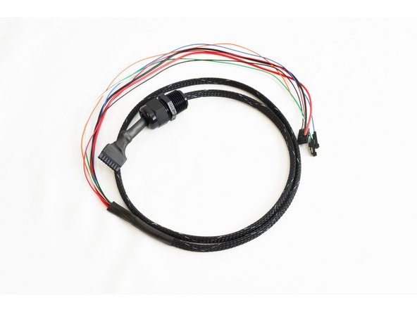
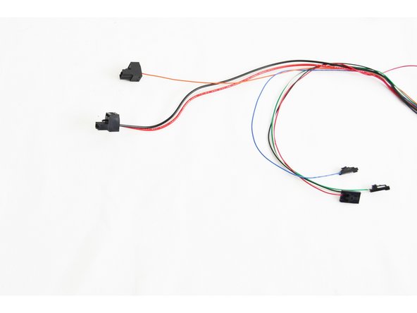
You will now install the supplied 2 position terminal plugs onto the remaining wires. (They are packed in the white box with the RAMBo board) The HE280 Whip Diagram shows the correct connections. These connectors can be found in the bag of terminals in the RAMBo box
-
Make sure the screws in the terminal blocks are as loose as possible to prevent strands of the wires being forced under the connectors.
-
The orange wire (Layer Fan) will be inserted into one of the 2 position terminal blocks.
-
The red and black wires (Hot End 12v power) will be inserted into the other 2 position terminal block.
-
Be sure to get the polarity correct (as shown in the diagram
-
Tighten the screw terminals as tight as possible, including the vacant position on the terminal block with the orange wire (layer fan).
The parts that you need here (the 2 position blocks) are the ones mentioned above that will be in a ziplock bag in the RAMBo box as step 1 mentioned. If you were me however, you had no idea what the RAMBo box was and were searching forever thinking it was lost. As it's not marked. The RAMBo box is the medium sized white box, inside a bag. The connectors are inside a smaller bag in that (not the bag taped to it), that says RAMBo v1.3 Kit. Hope that helps someone else save some time.
-
-
-
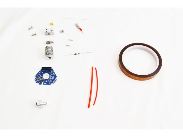
Locate the parts that will be used to assemble your HE280. They are part of the hardware pack 71290 which can be found in the final assembly hardware pack.
-
Some of the metal parts may have been loosely assembled before shipping. Separate them before proceeding.
-
SeeMeCNC runs the machine's parts through a cleaning routine to remove burs and other debris but you may find some remain. We recommend using a cotton swab to sweep the inside orifices to eliminate any remaining debris.
My heater cartridge did not have the ~8-10 mm of red insulation on the leads as shown in the photos. Instead mine had 20 mm of clear(ish) silicone insulation. I trimmed this insulation to ~10 mm to be consistent with the red insulation in the photos.
Dieter Weik - Resolved on Release Reply
The roll of Kapton tape is not part of the kit, and I believe where Kapton is needed it has already been applied.
Steve Hansel - Resolved on Release Reply
-
-
-
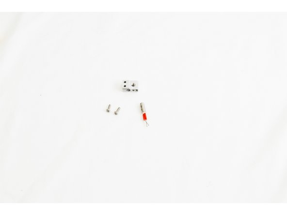
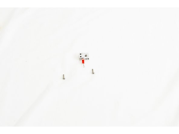
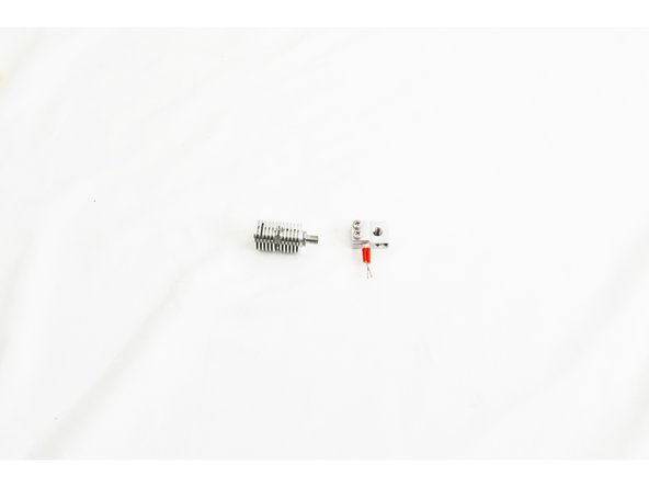
Locate the Heater Block (71216), 12v 40 watt Heater Cartridge (26789), and (2) M3 -.5 x 10mm Phillips Pan Head Machine Screws (30318)
-
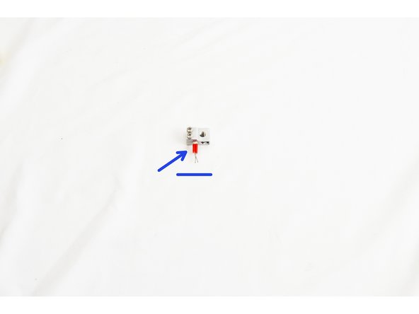
Insert the heater cartridge into the side of the heater block. The leads of the heater cartridge should stick out of the side of the heater block with 3 holes. The leads should be in a horizontal orientation and NOT VERTICAL. The heater cartridge should be inserted so that it is flush on the opposite face of the heater block.
-
Secure the heater cartridge in the heater block by tightening both of the M3 - .5 x 10mm screws.
-
Be sure to get these M3 - .5 x 10mm screws tight.
I replaced the Philips screws with M3-.5 x 10mm Allen head Cap screws (stainless steel type) for securing the heater cartridge. Cap screws will be easier to turn with Allen wrenches (using the L-bend) in this confined space compared to Philips heads, and the head less likely to strip. I also applied a dash of anti-sieze on these screw threads. All this in the name of easier maintenance down the road, if needed.
For steps 11-16 would you consider cropping the photos to show a more zoomed-in picture? Even at full screen some of these are hard to see. Thanks.
Tim Skloss - Resolved on Release Reply
-
-
-
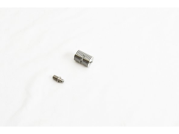
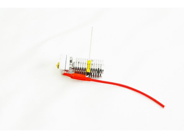
Locate the HE280 Heat Break and test fit the 4mm PTFE tubing. The tube should insert and fully seat.
-
Screw the heat break into the heat sink. The heat sink is symmetrical, so either end is OK.
-
Fully tighten the heat break using an 8mm or 5/16 wrench.
Where is this PTFE tubing? Is it shown in any of these 2 pixs?
In my case the PTFE tubing was originally inside the mesh loom from the wire whip step. Also, note when you test fit the tubing insert it on the end with the black tubing retainer thingy. Pull it all the way through rather than pushing it in part way and trying to pull it back out.
-
-
-
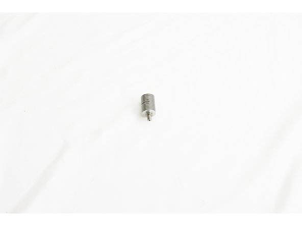
Screw the heat break into the heater block approximately 4mm.
-
It does not have anything to seat against yet, so will not be tight.
-
Screwing the heat break ~4mm deep is very important! The Nozzle should be able to go almost entirely into the heater block before getting stopped by the heat break.
-
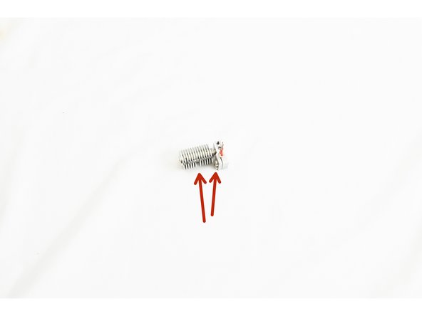
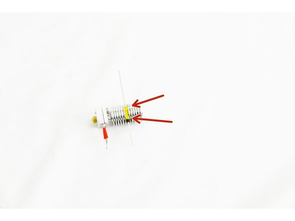
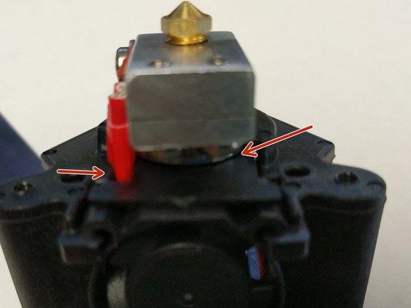
The most critical part of this step is that you get the round cut out in the heat sink running parallel with the heater cartridge, and on the same side as the M3 -.5 x10mm screws (as shown in pic, indicated with two red arrows)
-
-
-
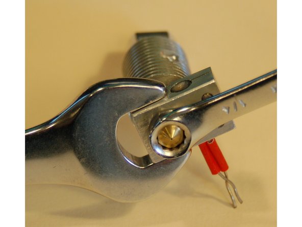
Locate the HE280 .5mm Brass Nozzle.
-
Screw the nozzle into the bottom of the heater block until it makes contact with the heat break. Finger tight!
-
On the next step, tightening the nozzle, be sure not to damage the heater cartridge with the 15mm or 5/8 wrench.
-
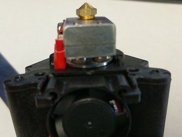
Be sure the Nozzle is screwed in almost all the way before starting to tighten. You should be able to see one row of threads when fully tightened. See Pic #2.
-
Tighten the nozzle fully, using a 15mm or 5/8 wrench on the heater block and a 6mm or 1/4 wrench on the nozzle.
-
It shouldn't take more than a 1/4-1/2 turn from the wrench to snug up the nozzle. If it isn't tightening, you started with the heat break screwed in too far and the nozzle not screwed in enough. Don't make an expensive mistake.
-
-
-
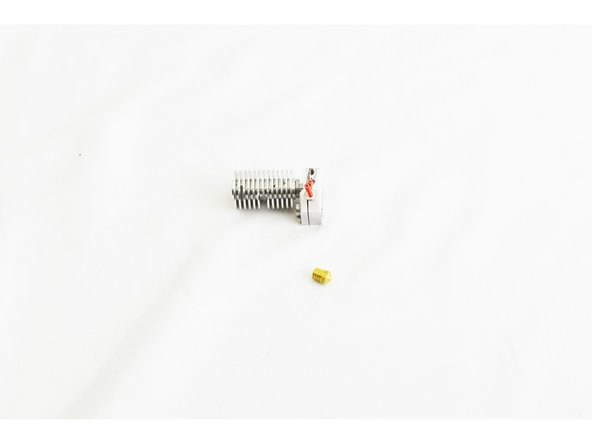
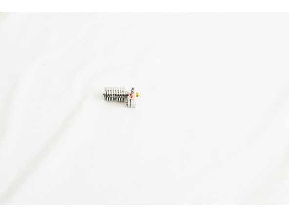
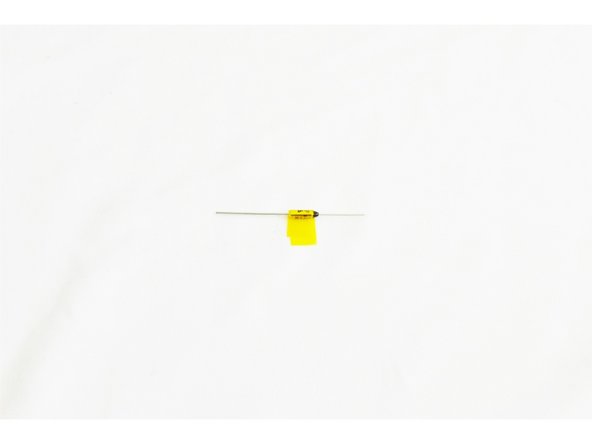
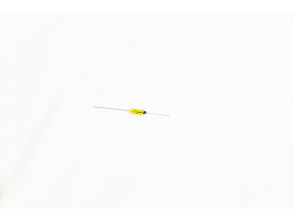
Locate the Thermal Safety Fuse (26792).
-
It will come from SeeMeCNC with Kapton Tape already wrapped around it and taped to itself.
-
Trim the Kapton Tape as shown in the image.
My Kit doesn’t appear to have a thermal safety fuse or thermistor. I think the thermistor is the cartridge type.. Does anyone have a link to a more up to date guide?
Jason E Hurst - Resolved on Release Reply
-
-
-
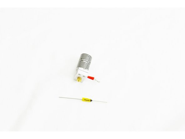
Slide the thermal safety fuse into the side of the heat sink with the black epoxy coated end being on the same side as the leads for the heater cartridge.
-
If the fit is too tight, a standard screwdriver may be used to slightly flex the fins of the heat sink apart enough the slide the thermal fuse in. Be sure not to flex the fins too much, as this will prevent it from having good contact with the fins.
-
You should center the thermal fuse in in the heat sink.
-
After the thermal safety fuse is in place, use the standard screw driver to flex gently flex the fin above and below the fuse so that it is held securely in place.
be careful not to scrape the kapton tape off the thermal fuse as you are sliding it into place against the sharp cooling fins
Samuel Sharpless - Resolved on Release Reply
-
-
-
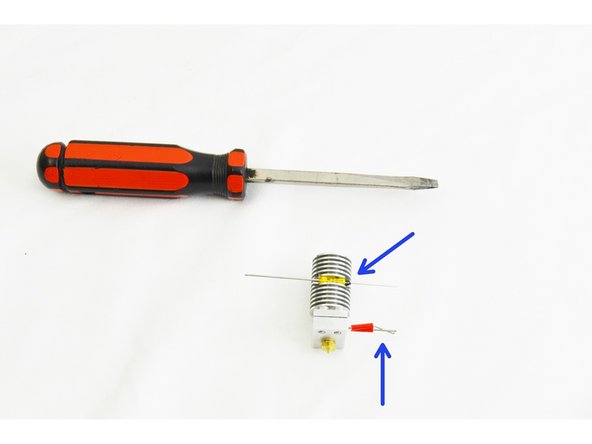
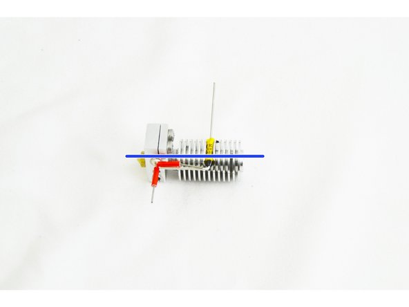
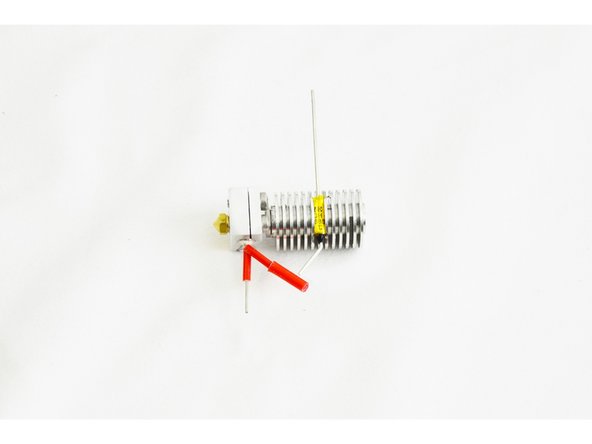
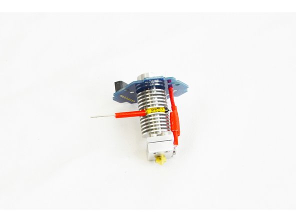
Using a pair of needle nose pliers, bend the lead of the thermal safety fuse (the side with the black epoxy coating) at a 90 degree angle, making it parallel with the heat sink, heat break, and nozzle.
-
Perform the same operation with one of the leads belonging to the heater cartridge.
-
Note that you may need to trim the lead of the thermal safety fuse so that the end of the lead comes even with the end of the red insulation sleeve.
Warning, you may want to skip ahead and look at step 37. There is a piece of plastic that has to fit over all these connections and if you don’t keep your bends and wires very close to the heat sink, the plastic won’t fit. I normally keep a little space between the part body and the first bend, but that may have screwed me in this case.
Steve Hansel - Resolved on Release Reply
-
-
-
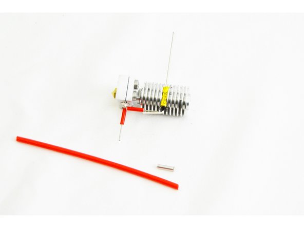
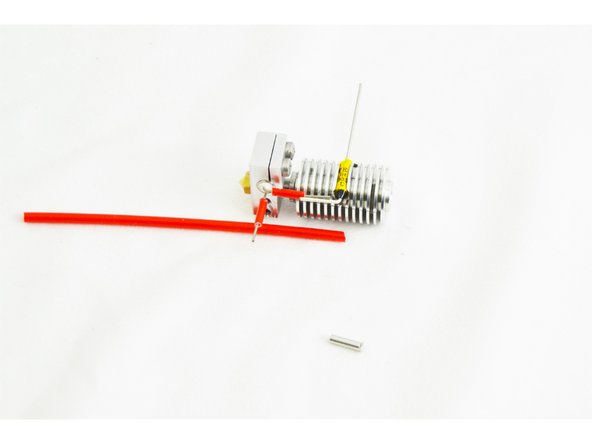
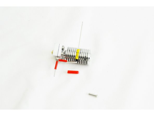
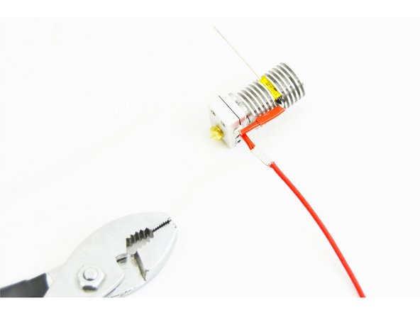
Locate one of the Non-insulated Wire Ferrules (26222) and the 55mm long Red Silicone High Temp Insulation (26191).
-
Your supplied red silicone high temp insulation will not be as long as that indicated in the images.
-
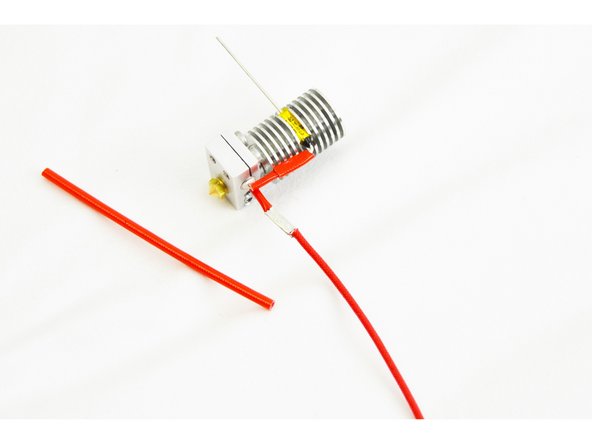
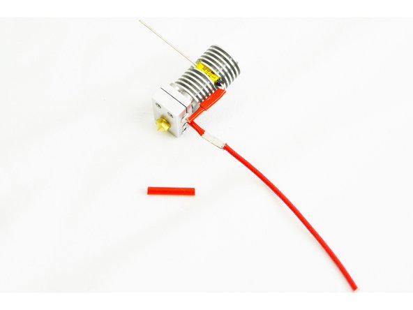
Cut the red silicone high temp insulation into 3 pieces 18mm long.
-
-
-
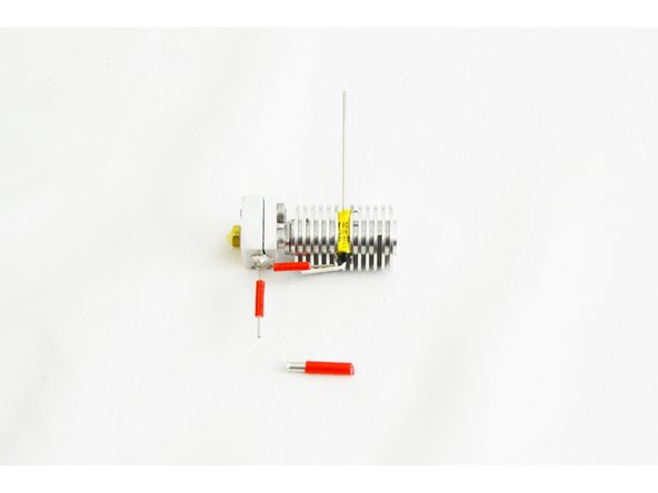
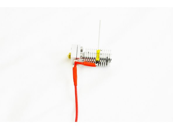
Insert the non-insulated wire ferrule into one of the pieces of red silicone high temp insulation, centering it.
-
-
-
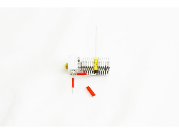
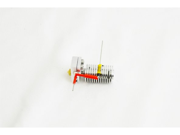
Slightly bend out the leads from the heater cartridge and the thermal safety fuse.
-
Slide the ferrule (with insulation installed) over the heater cartridge lead, and then manipulate the lead from the thermal safety fuse to get it inserted into the other end of the ferrule.
-
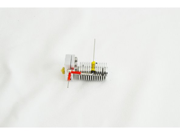
Straighten the leads back out so they are running nearly parallel with the heat sink, heat break, and nozzle.
-
-
-
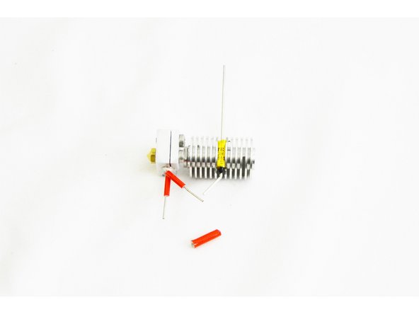
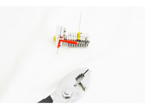
Use a pair of pliers to crimp the ferrule to the leads. Do this in three steps: roughly locate the midpoint of the ferrule and crimp the upper portion (side with the thermal safety fuse lead), then the lower side (side with the heater cartridge lead), and finally crimp, one last time in the center of the ferrule.
-
Do this carefully. It does not take much force. You WILL damage the insulation if you squeeze too hard.
I found it easier to trim the heater lead 2mm shorter than where the fuse lead is bent. Then trim the fuse lead 2mm shorter that the ferrule against the bend. Remove the heater cartridge from the block and slide the big silicone over the little silicone on the bent lead. Slide the ferrule over the fuse lead, and the heater lead into the ferrule. Carefully fiddle with the whole assembly until the heater is back in the block with the fuse & heater leads in the ferrule. The big and little silicone tubing are squished against the heater, and the ferrule is against the bend in the fuse lead. Crimp the naked ferrule, then slide the big silicone over it to insulate. I also squirted a little copper anti-seize compound into the ferrule before crimping for a lower resistance connection.
-
-
-
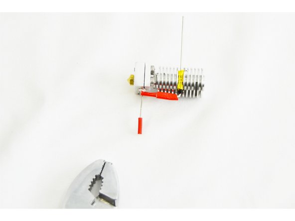
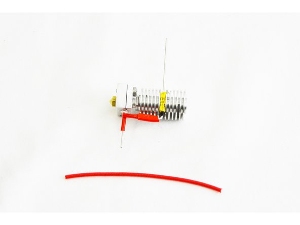
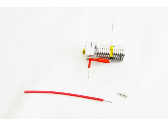
Locate the other Non-Insulated Wire Ferrule (26222) and the High Temp Fiberglass Insulated Wire (26192)
-
Strip 10mm of insulation from one end of the High Temp Fiberglass Insulated Wire and 6mm from the other end.
-
Slide the wire ferrule over the end of the lead on the heater cartridge.
You should probably slide the silicone insulation over the wire before you strip it, as the spare ends of the insulating fiber make it really hard to slide the insulating sleeve over the wire after it is stripped. I made a big mess of mine and had to pull the crimp off trying to do it after crimping the parts together in later steps.
-
-
-
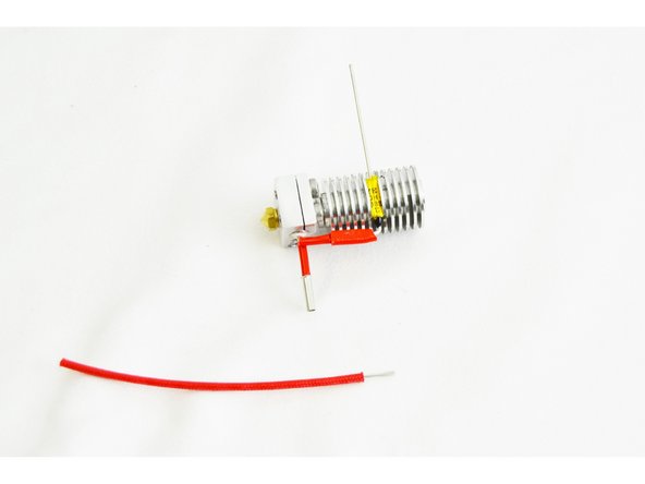
Slide the High Temp Fiberglass Insulated Wire (side with 10mm stripped, into the other end of the wire ferrule (inserted in the last step)
-
You should insert the High Temp Fiberglass Insulated Wire until the insulation is flush with the end of the wire ferrule.
-
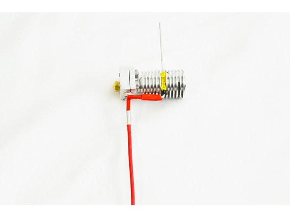
Crimp the wire ferrule. Do this in three steps, roughly locate the midpoint of the ferrule and crimp the upper portion (side with the heater cartridge lead), then the lower side (side with the high temp wire), and finally crimp one last time in the center of the ferrule.
Crimping instructions appear to have been copy-pasted from step 21. The parenthetical descriptions of the ends of the crimp don't make sense for this step. I'm guessing that the first end to crimp is the non-flaring end, but someone else should confirm this.
John Wolter - Resolved on Release Reply
-
-
-
Install one of the reminaing 18mm pieces of Red Silicone High Temp Insulation over the connection that was crimped in the previous step.
-
Ensure that the insulation is fully covering the wire ferrule.
-
-
-
Bend the prepared lead from the heater cartridge, up at a 90 degree angle. This lead should now be parallel with the lead going to the thermal safety fuse.
-
-
-
Be careful with the Thermistor, it is a fragile component, if handled too rough it will break.
-
Due to their fragile nature, for orders shipped after 9/27/16, we have included a spare thermistor in your HE280 Hotend kit.
-
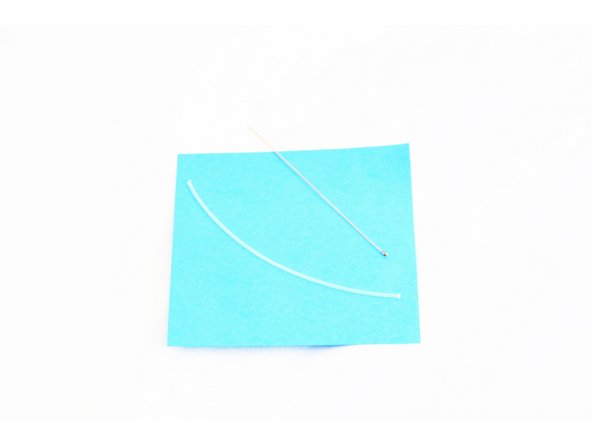
Locate the Thermistor 100K (26141) and 100mm long Small PTFE Tube (26190)
-
Cut the 100mm long small PTFE tube in half. You will now have two pieces that are 50mm long each.
-
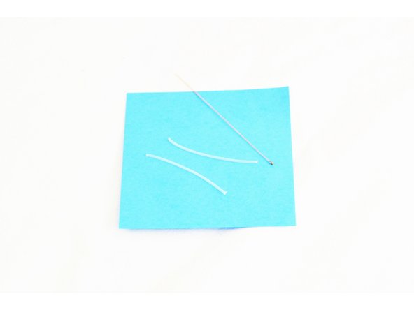
Carefully slide one 50mm tube up one leg of the thermistor, then repeat for the other leg. The tubing should reach up to the glass bead on the thermistor. Do not force the tubes as this may split the thermistor head.
I was given 2 sections of PTFE Tube each about 70mm long (one with each thermistor). I think in this case, we don’t want to cut one in half, but cut them both to 50mm or slightly longer.
Steve Hansel - Resolved on Release Reply
Do not cut the PTFE tubing into two 50mm sections, just cut it in half. 50mm was too short to cover one thermistor wire in my build.
jay armstrong - Resolved on Release Reply
Be careful with the PTFE tubes. If you push the tubes right up to the thermistor it will split in half with very little effort. After breaking my first thermistor I used tweezers to hold the wire leads instead of the glass thermistor body.
Tim Skloss - Resolved on Release Reply
+1, I'm not a newbie and I crash the thermistor as you said, inserted PTFE is very tricky...
Greesha -
-
-
-
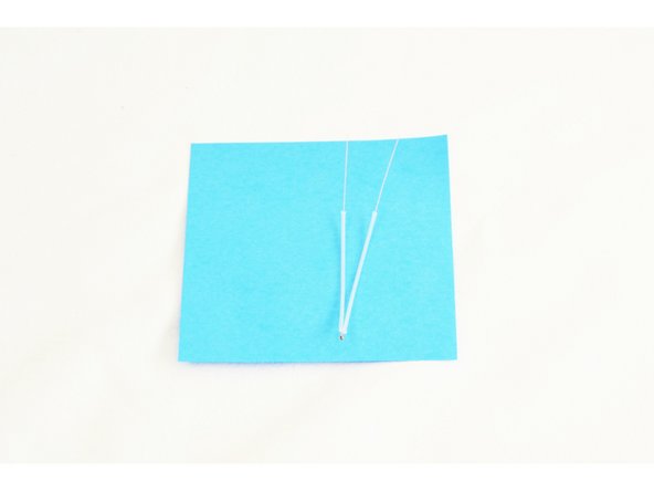
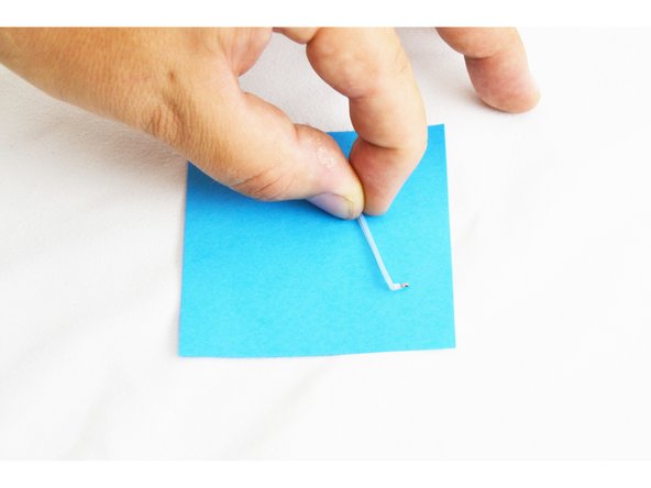
Make a 90 degree bend at the end of the thermistor / PTFE Tube (the end with the glass bead) using a pair of needle-nose pliers.
-
To do this: Pinch the needle-nose pliers onto the edge PTFE that is covering the legs of the thermistor, and rotate the needle-nose pliers, making the 90 degree bend.
-
Compare your result with the picture.
I found it’s easier to control by pinching the tip with needle-nose pliers and bending the wires underneath (rather than twisting the pliers).
Kurt Frymire - Resolved on Release Reply
Somewhere between this step and the next one, it appears that the arrangement went from two thermistor leads inside one piece of PFTE to one lead each inside two separate pieces of PFTE. This should be clarified.
John Wolter - Resolved on Release Reply
-
-
-
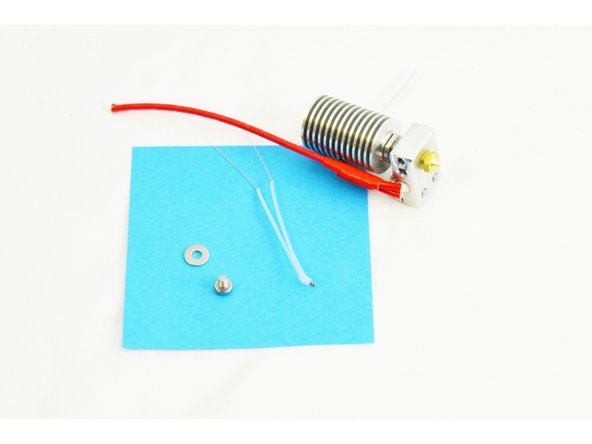
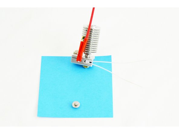
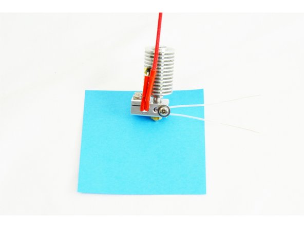
Locate the M3 -.5 x 6mm Phillips Head PH Machine Screw (30317) and the #4 SAE Flat Washer (30449)
-
Insert the thermistor (glass bead end first) into the hole (closest to the heater cartridge) in the side of the heater block.
-
Insert the #4 washer onto the M3 screw (sharp edges facing the head of the screw), and then insert the screw into the hole (furthest from the heater cartridge) in the side of the heater block.
-
Fully Tighten.
I assume the Thermistor is an NTC (Negative Temperature Coefficient) type? Is there a commercial part number (and equivalents) in case it needs replacement? (yes, my kit came with a spare). It's used here as a temperature sensor (yes?), so for step 28, would it be adviseable, or not adviseable, to place some thermal or heatsink paste into the hole before inserting the thermistor, just so it has a good thermal contact with the heater block?
-
-
-
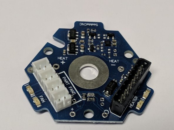
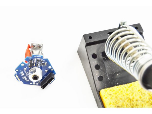
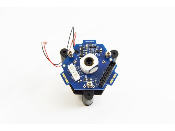
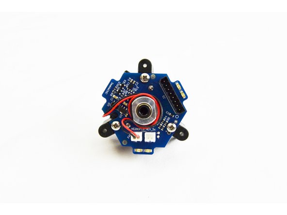
HE280 kits now shipped from SeeMeCNC include a REV6A accelerometer board as picture to the left.
-
The most notable difference is that there are separate connectors for the 3 layer fans. This eliminates wire splicing the fans together.
-
If later steps are affected by the change, the instruction steps will note REV5 or REV 6 steps separately.
-
-
-
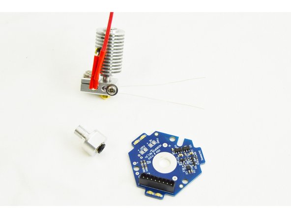
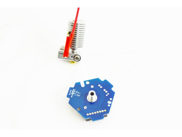
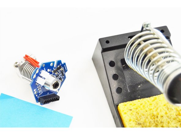
Locate the HE280 Hotend PCB Board (71210) and the EZR Struder / Hot End PTC Adapter (70604)
-
Insert the EZR Struder / Hot End PTC Adapter through the hole in the center of the HE280 Hotend PCB Board
-
The black plastic ring of the EZR Struder / Hot End PTC Adapter should be on the side of the HE280 Hotend PCB Board with the 8 pin connector (See Pic)
-
Hand-tighten the EZR Struder and HE280 Hotend PCB onto the heat sink. Align the PCB so that branded "SeeMeCNC" tab is parallel to the fastener end of the heat block (see image for reference).
12/17/17 - the printed circuit board has changed slightly. There are now four fan connectors pre-soldered to the board
Samuel Sharpless - Resolved on Release Reply
-
-
-
Confirm the correct alignment of the HE280 Hotend PCB Board with the rest of the hot end assembly.
-
Once confirmed, fully tighten the EZR Struder / Hot End PTC Adapter
-
-
-
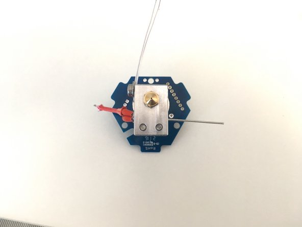
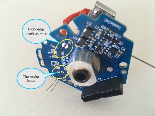
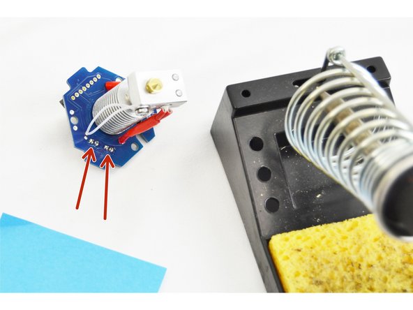
Flex the high temp insulated wire that is crimped onto the heater cartridge and insert it into the through hole on the HE280 Hotend PCB marked with a +
-
The high temp insulated wire should extend through the PCB board with the insulation resting against the bottom of the board.
-
Feed the thermistor wires through the two holes just to the right of "PART +" (or the holes marked "TEMP"). See image for reference.
-
The PTFE tubing on the legs of the themistor should rest against the bottom of the HE280 Hotend PCB board. It is ok if the thermistor leads have a slight bow to them between the heater block and the PCB, this is actually preferred, so do not trim the PTFE/legs down from the stock length.
It is not clear what the arrow on the right is pointing too. Too verify, the thermistor leads insert into the 2 holes that are 2mm apart with no label next to the holes. The hole the arrow points too seems to be the one with a + next to it, I don't think that is the correct one.
Michael Hackney - Resolved on Release Reply
-
-
-
Insert the remaining piece of 18mm red silicone high temp insulation on the leg of the thermal safety fuse.
-
Flex the leg of the thermal safety fuse down enough that it can be inserted into the HE280 Hotend PCB Board through hole opposite of the +
-
Noted indication marker in photo.
This would be easier to do while attaching the HE280 PCB to the heat sink.
Kurt Frymire - Resolved on Release Reply
-
-
-
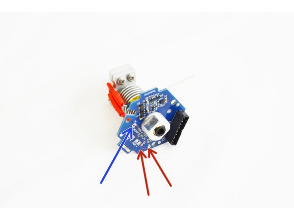
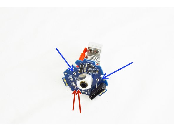
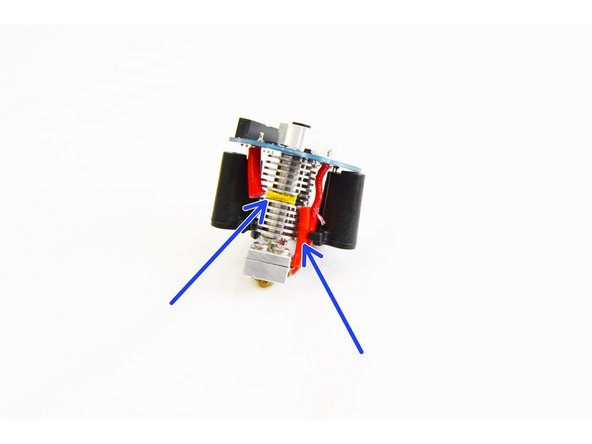
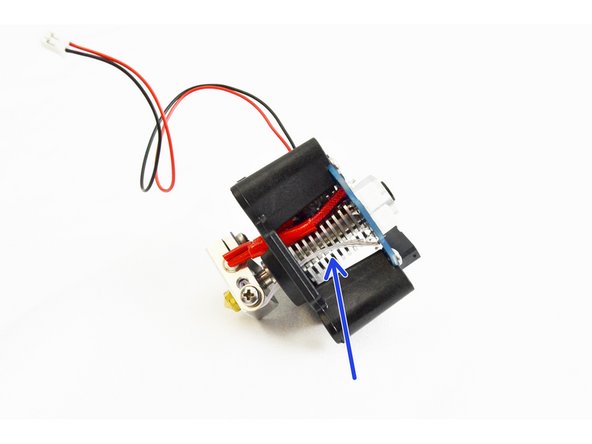
Confirm that you have the heater cartridge lead and the thermal safety fuse leg inserted in the through holes of the HE280 Hotend PCB board.
-
In photo #1 the heater cartridge lead is on the left (indicated by the + on the HE280 Hotend PCB board) and the thermal safety fuse is on the right. (noted with blue arrows)
-
Confirm that the thermistor legs are inserted into the correct through hole location (marked with red arrows in the picture) on the HE280 Hotend PCB board.
-
Using your soldering iron, solder all 4 through hole connections.
-
-
-
After the through hole connections have been soldered, trim the excess thermistor leads on the top side of the HE280 Hotend PCB board. These do NOT need to be flush with the board, we just need to ensure that they can not short against each other.
-
-
-
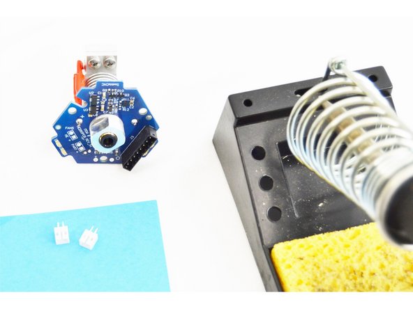
If you have received a REV6 accelerometer board, this step is NOT required.
-
Locate the (2) Header 2 Pin JST PH2.0 (26176)
-
Insert and orient the parts as shown in the picture. The solid face of the plug should be facing towards the center of the hot end.
-
Solder those two plugs (4 total solder points in place from the bottom side of the HE280 Hotend PCB board.
-
If you pinch the leads on the white connectors a tiny bit, they'll "grip" the PCB and make them easier to solder.
-
-
-
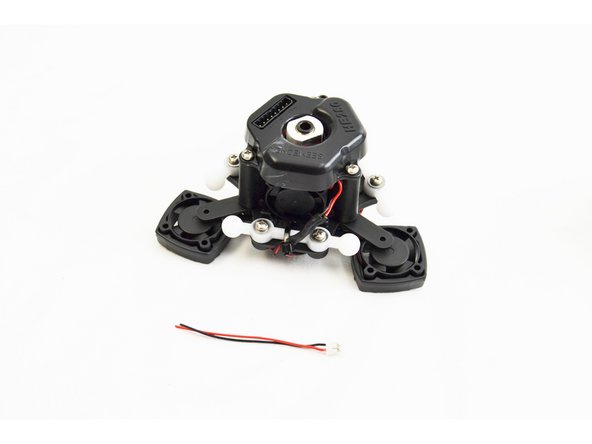
In the picture are the parts that will be required for the final assembly of the HE280 Hot End.
-
Not included in the picture is a 30mm long piece of 1/8" Heatshrink tubing & 2 additional Layer Fan Mounts .
-
-
-
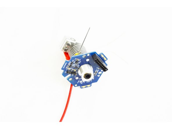
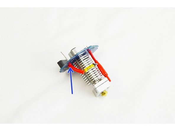
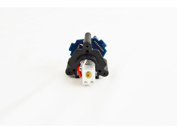
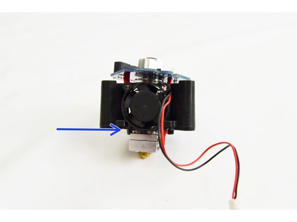
Locate the HE280 PCB Mount (71257)
-
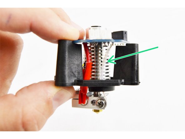
Align the hotend with the PCB mount as shown in the image and gently slide it in place.
-
Notice that the side of the heat sink that contains the thermal safety fuse should be on the side of the PCB mount with the opening. (indicated with blue arrows)
-
You will want to arc the thermistor leads slightly as shown in the image (indicated by a green arrow) so they are not pinched between the hot end and the PCB Mount when fastening.
Yep. Me too. Used a Dremel, then cleaned up with a file. Careful not to take off too much material.
Dieter Weik - Resolved on Release Reply
The PCB mount in my kit didn't have enough clearance for the red heater cartridge wires or the thermistor leads. I used a small round file to create a small notch in the PCB mount for the thermistor leads, and I removed some additional material around the heater leads. Then it went together without any binding.
Tim Skloss - Resolved on Release Reply
-
-
-
Locate (1) of the 25mm Ball Bearing (26309) Fans.
-
Tilt the fan at a slight angle and slide the it into the fan mount legs of the PCB mount. THE SIDE OF THE FAN WITH THE LABEL SHOULD BE CLOSEST TO THE HOT END HEAT SINK.
-
The final location of the fan is with the bottom edge flush with the bottom of the PCB mount.
-
-
-
Locate (3) of the #4 x 3/8" sheet metal screws (30250).
-
Align the holes in the PCB with the holes in the PCB mount and insert the screws in to each of the three locations. DO NOT TIGHTEN YET
-
Ensure that the thermistor legs still have a slight arc and are not in the direct rear of the hot end where they can be pinched.
-
Tighten each of the three screws two complete turns and then check the thermistor legs.
-
Repeat as necessary until fully tightened.
The red end of the thermal safety fuse was REALLY in the way. And pushing on it to try to bend it would try to push it out of the heat sink. Anyway, had to use the screws to basically clamp down on it after lots of fighting. Changing the instructions above to route the cable a little better/differently so that it won't be in the way could be super helpful. But after soldering it was too late.
-
-
-
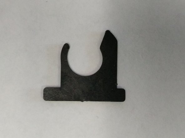
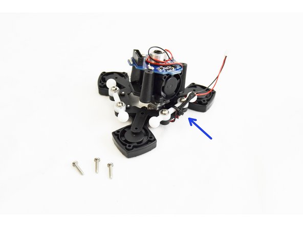
Kits shipped after 2/24/2017 from SeeMeCNC come with a Barrel Fan Blocker (shown in first image). If your kit is from a prior date, you can print your own. Barrel Fan Blocker Install after initial assembly will not be an issue.
-
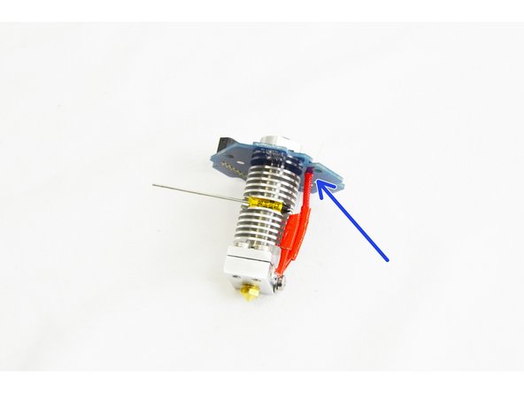
Locate the barrel fan blocker from your hot end kit.
-
Align the barrel fan blocker with the visible fin on the heat sink between the hot end stand off and the heater block. The blocker is not symmetrical, the side with the skinnier leg will be on the side of the heater cartridge leads.
-
Press the barrel fan blocker in until you feel it "snap" onto the heat sink.
-
This blocker will help to prevent any airflow from the barrel fan from making it down to the heater block.
-
-
-
Run the 25mm fan wire up and through the notch in the PCB, wrap it around the PTC adapter in the center of the hot end and then plug it into the HE header on the PCB.
-
This connection is keyed. This will aid in ensuring polarity is correct.
CHECK YOUR PCB CONNECTORS. The connectors on my PCB are installed the wrong way around, so the Red and Black wires are not oriented as shown in the diagram. My fans did not run. I was able to unlock the crimp-pins on the wires and swap the wires and now the Red/Black orientation is as shows in the image and my fans run.
Alan Kilian - Resolved on Release Reply
-
-
-
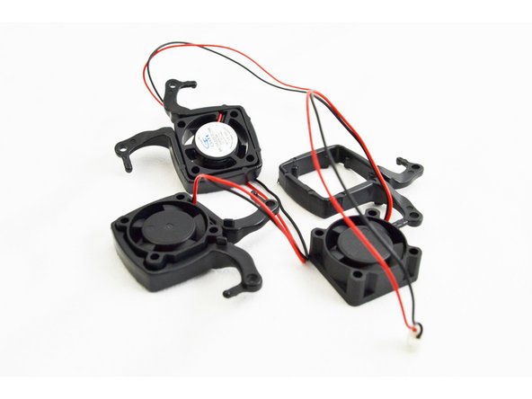
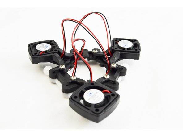
Locate the remaining (3) 25mm Ball Bearing Fans (26309) and HE280 Layer Fan Mounts (71259).
-
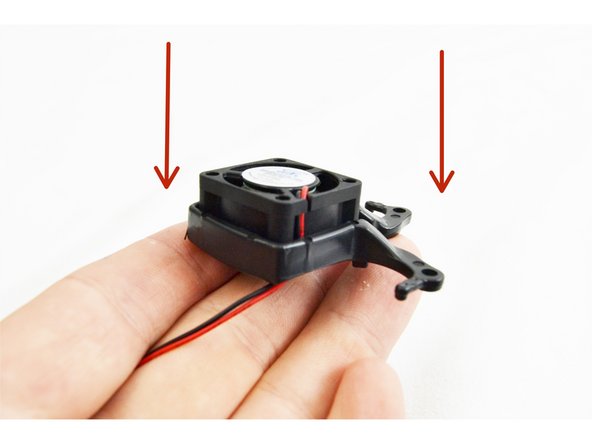
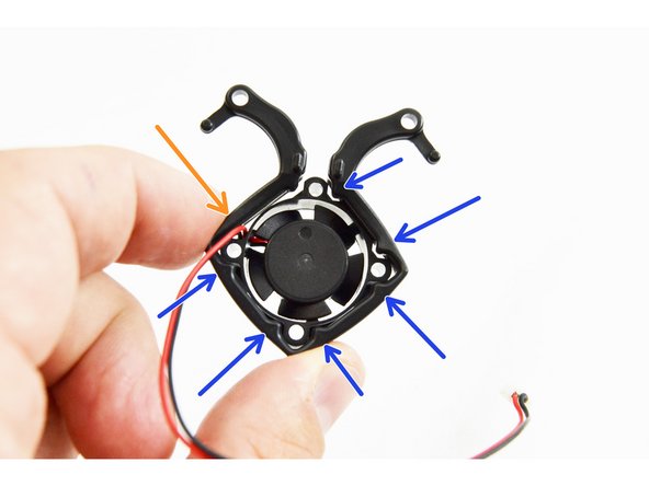
Insert (1) fan into each fan mount as show in the image.
-
Pay close attention to the orientation of the fan leads and direction of installation.
-
The fans should be installed into the fan mounts in the direction indicated by red arrows in the image.
-
The fan should be oriented so that the leads that exit the fan are located where there is not an alignment pin. This is indicated in the image by an orange arrow, the alignment pins are indicated with blue arrow.
-
-
-
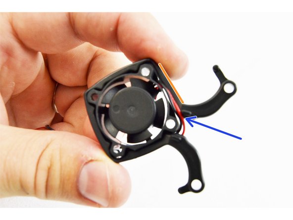
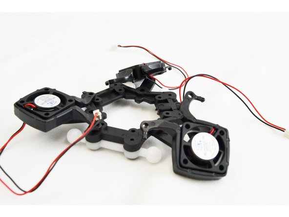
When correctly installed the fan and mount should look like this image.
-
Route the wires along the fan body then in between the boss and the fan body, finally dropping straight down.
-
-
-
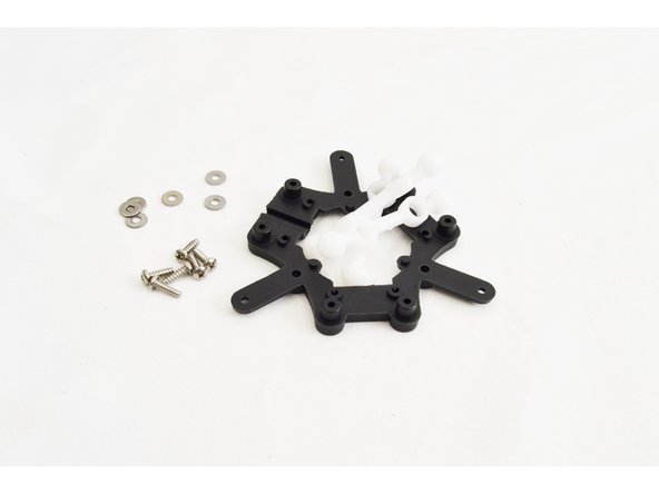
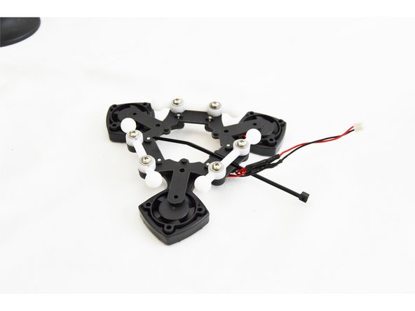
From the 290mm IM Arm / Platform Sub-Assembly Pack (70871), locate the Ball Joint Platform (70857), (3) Ball Joints for IM Carriage/Platform (70855), (6) #4 x 3/8" sheet metal screws (30250), and (6) #4 SAE Flat Washers (30449). Set the rest of the parts from that pack aside for later use in Final Assembly.
-
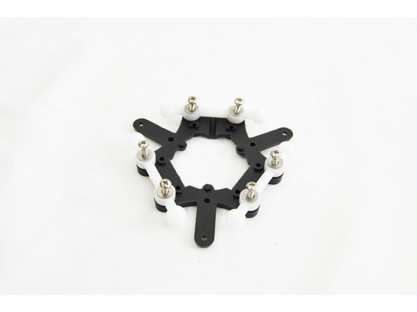
Install the joints onto each of the three sets of posts on the ball joint platform as shown.
-
Install a #4 washer and #4 x 3/8" sheet metal screw into each post to secure the ball joints.
-
Fully Tighten.
-
-
-
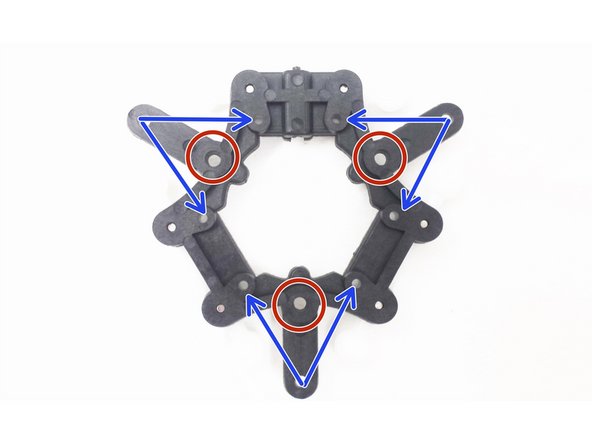
The red circles indicate where you will secure the Hotend with PCB mount to the ball joint platform.
-
The blue arrow sets indicate where you will secure the layer fan mounts to the ball joint platform.
-
Keep these reminders in mind for the following steps. Refer back as needed.
-
-
-
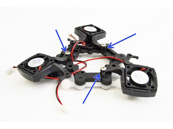
Locate (6) of the #4 x 3/8" sheet metal screws (30250) from the HE280 Complete Hot End Kit.
-
Secure one leg of each fan mount into the hole on the bottom of the ball joint platform.
-
Loosely route the fan wires for each fan up and in between the legs of the layer fan shroud mount. This is indicated with orange arrows.
I have 5 fingers on each hand and that didn't seem like enough to get these fan mounts secured. The first screw is easy, but I had to compress the fan mount significantly so the second screw could be inserted. It makes a nice, tight apparatus when complete, it was just a bit cumbersome to hold the mount in compression while trying to get the screw started.
Tim Skloss - Resolved on Release Reply
I think this step could be arranged differently. I found it easier to go Lego Technic manual style. Prototype it out on the first leg, repeat for the other 2 fans. With all 3 fans attached with 1 leg, it was a bit of a struggle to keep everything in order. Too many dangling bits.
Joe Modjeski - Resolved on Release Reply
-
-
-
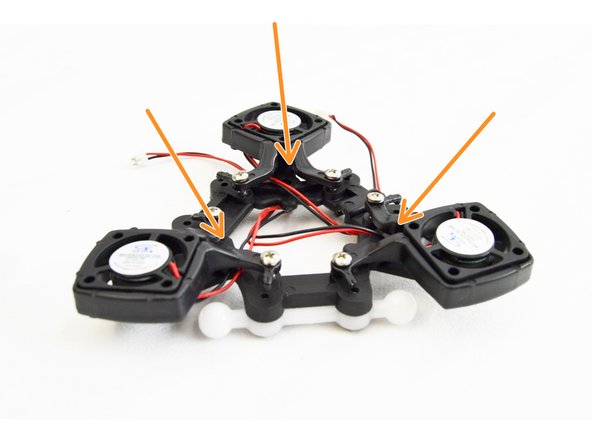
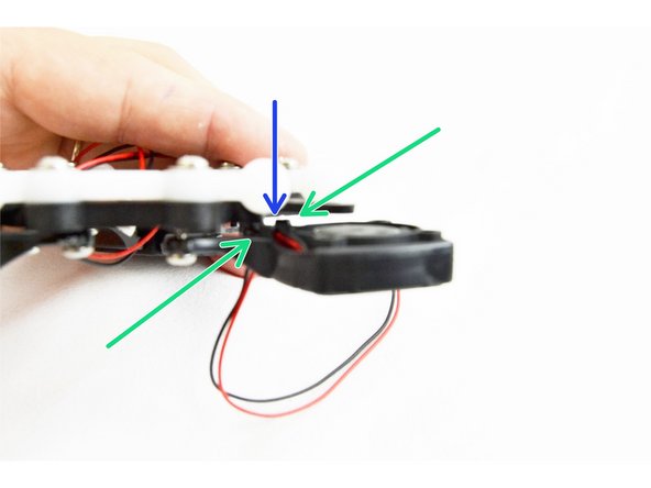
Route the fan leads along the body of the fan and in between the two bosses (indicated with green arrows)
-
DO NOT PULL SO TIGHT AS TO RIP THEM OFF THE FAN, but pull the leads taught on the bottom side
-
Insert the remaining #4 x 3/8" sheet metal screws into the fan mounts.
-
With the screws inserted you will need to flex the legs of the layer fan mount into place and start the screw into the hole. Do not fully tighten yet.
-
Flexing the legs of the layer fan mount helps to pinch on the fan, locking it in place.
-
After you have all the layer fans attached and partially tightened, work on fully tightening one fan mount at a time. As you work toward having these fully tightened, ensure that the wires are routing correctly and have not moved from their expected position.
-
-
-
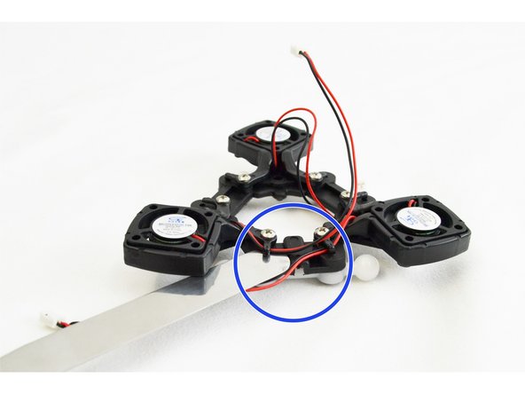
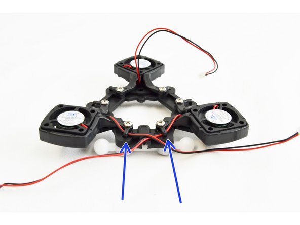
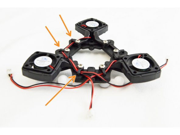
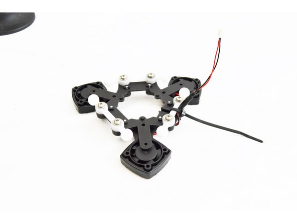
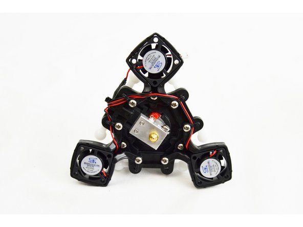
We will now route the fan leads on the bottom of the ball joint platform.
-
Begin with the (2) layer fans that are closest to the channel in the ball joint platform (indicated by the blue circle). You will want to GENTLY flex up the wire management tab with a flat tool. You will route the leads of the (2) fans closest to the channel towards that channel.
-
Next you will route the leads of the layer fan farthest from the channel. These fan leads will go under 3 wire management tabs as they pass around the perimeter of the ball joint platform.
-
Press down (by hand) any of the wire management tabs that were flexed up for this step.
-
-
-
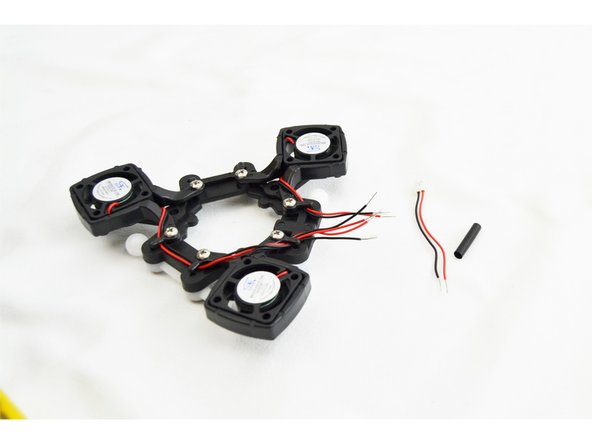
If you have received a REV6 accelerometer board, this step is NOT required. There is a connector for wach fan on the board.
-
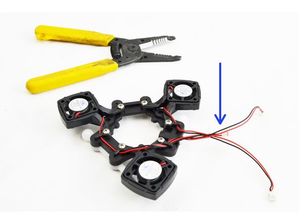
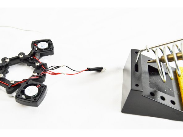
READ ALL STEPS BEFORE PROCEEDING! Wiring the Effector Platform Fans for the Rostock MAX v3
-
You will be cutting the plug off of the shortest fan lead first. You want to cut the leads as close to the plug as possible.
-
You will now cut the remaining (2) sets of fan leads to the same length as the first.
-
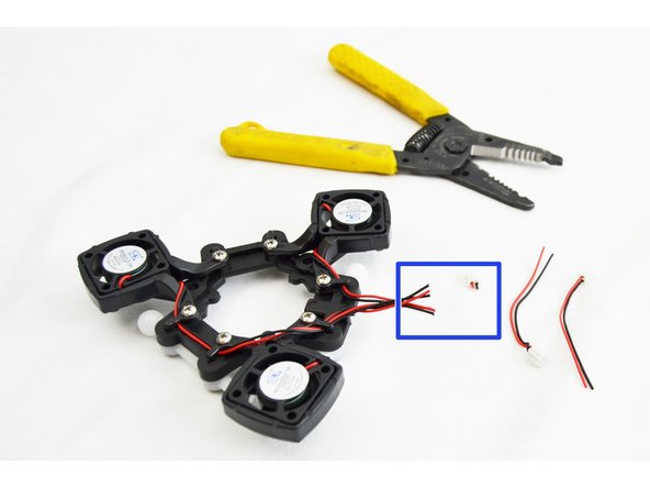
DO NOT DISCARD THE LEAD AND PLUGS THAT YOU CUT OFF. THESE WILL BE USED WHEN INSTALLING THE RAMBO BOARD. THEY WILL BE ATTACHED TO THE 40mm BALL BEARING FAN ALLOWING IT TO PLUG INTO THE RAMBo BOARD.
-
Strip approximately 5mm of insulation from each of the leads that you cut.
12/17/17 - STOP! read ahead to step 56! on my version of the board, there are three pre-installed headers, one for each fan connector. There is no need to cut or splice the part fans.
Samuel Sharpless - Resolved on Release Reply
-
-
-
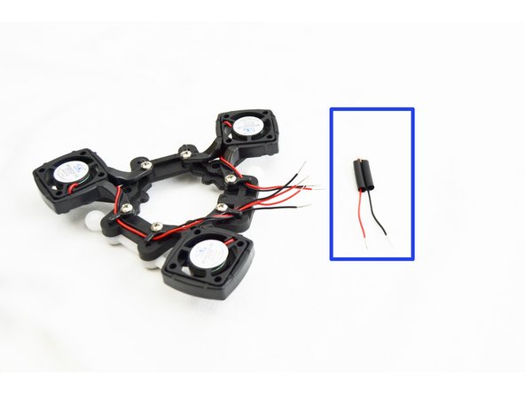
If you have received a REV6 accelerometer board, this step is NOT required. There is a connector for each fan on the board.
-
Locate the 1/8" Heat Shrink Tubing 30mm long.
-
Cut the heat shrink tubing in half
-
Insert each piece over the legs of one of the leads/plug that you cut off in recent steps.
-
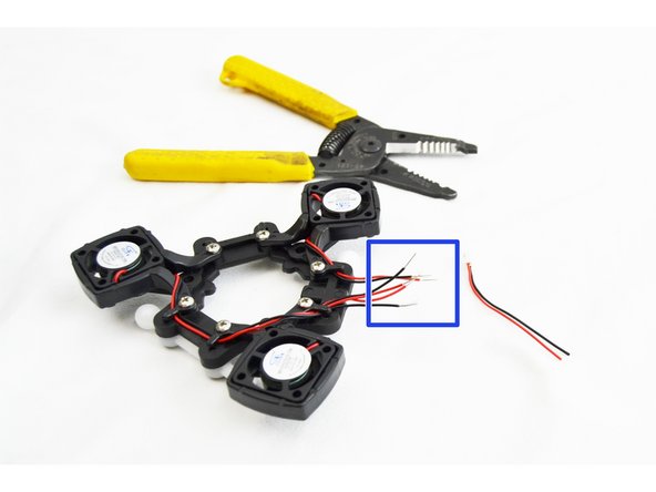
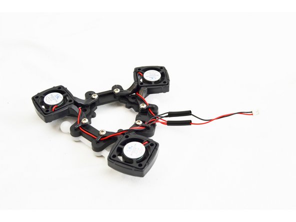
Twist the three red fan leads together (the ones still connected to the fans)
-
Twist the three black fan leads together (the ones still connected to the fans)
-
-
-
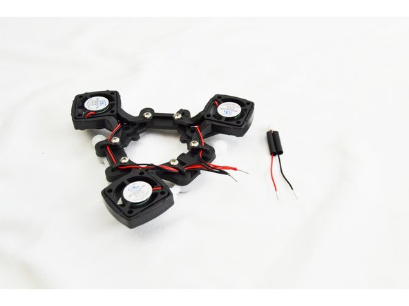
If you have received a REV6 accelerometer board, this step is NOT required. There is a connector for each fan on the board.
-
You will now perform an in-line splice soldered connection of the three bundled leads with the lead that has the plug installed. You will perform this type of splice for the red and black wires (separately) as shown in the images.
-
Be sure before soldering that you have the heat shrink tube installed and slid to the end of the lead with the plug.
I recommend using the longest cut lead you have for this splice! Otherwise, your newly soldered lead may not reach its plug in a later step.
jay armstrong - Resolved on Release Reply
-
-
-
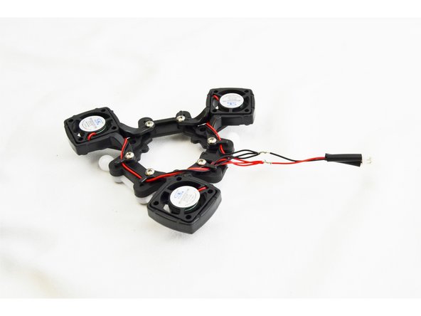
If you have received a REV6 accelerometer board, this step is NOT required. There is a connector for wach fan on the board.
-
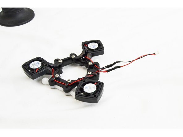
Slide the heat shrink tubing over the (2) spliced connections and apply heat, shrinking it onto the leads.
-
-
-
If you have received a REV6 accelerometer board, this step is NOT required. There is a connector for each fan on the board. After you get the hot end installed on the platform in step 56, you will find the best routing for the fan wires.
-
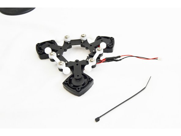
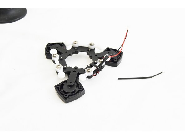
Install a wire tie to secure the leads you just worked on to the ball joint. The wire tie will route through the channel in the ball joint platform as shown in the picture.
-
-
-
-
If you have received a REV6 accelerometer board, this step is NOT required. There is a connector for each fan on the board. After you get the hot end installed on the platform in step 56, you will find the best routing for the fan wires.
-
Cut off the excess portion of the wire tie.
-
-
-
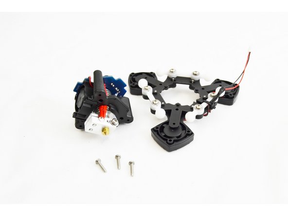
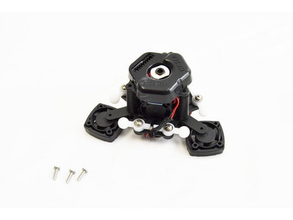
Locate the (3) #4 x 1/2" sheet metal screws
-
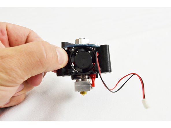
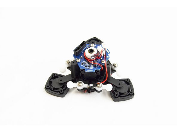
Orient the hotend assembly with the platform assembly such that the hotend fan is parallel with the ball joint that has the layer fan leads connected to it.
-
The hotend assembly will index onto the ball joint platform via 3 bosses / recesses This will help with aligning the screw holes.
-
Use the (3) #4 x 1/2" sheet metal screws to secure the two together.
-
Fully Tighten.
I had to plug in the layer fan (step 56) before screwing these parts together because the wires was too short.
jay armstrong - Resolved on Release Reply
-
-
-
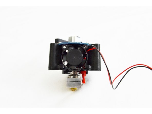
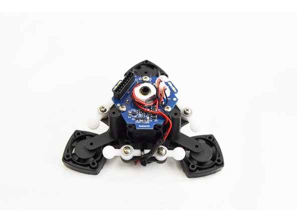
Route the wires for the heat sink cooling fan in the notch on the PCB and plug it into the HE port.
-
REV5 BOARD ONLY: Route the wires for the layer fans through the same notch in the PCB that you routed the hot end fan.
-
REV6 Boards will have to route each fan lead up to the board separately as shown in the third image. You may have to re-route the wires that you did in step 49 to find the best route to the fan connectors.
-
Plug the layer fan into the HE280 Hotend PCB board port labeled "PART"
-
-
-
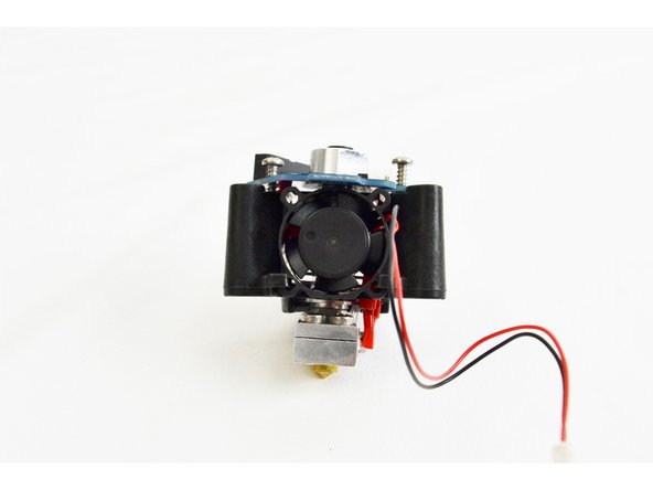
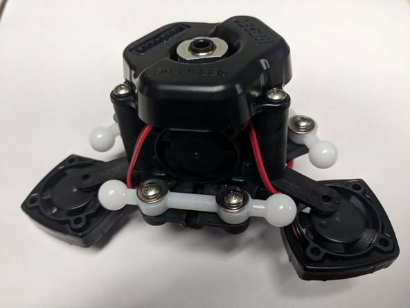
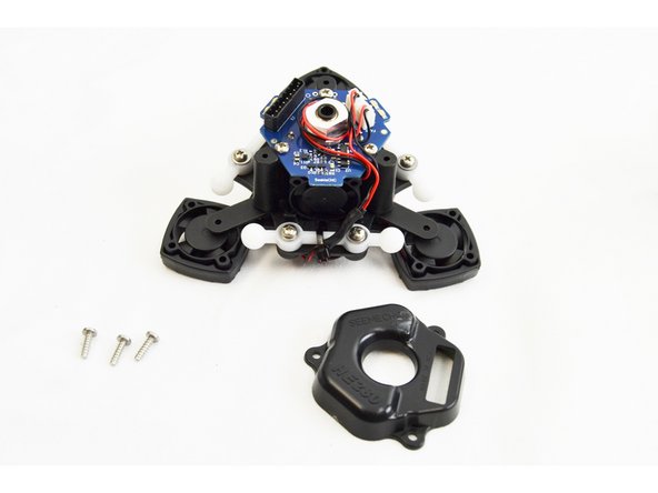
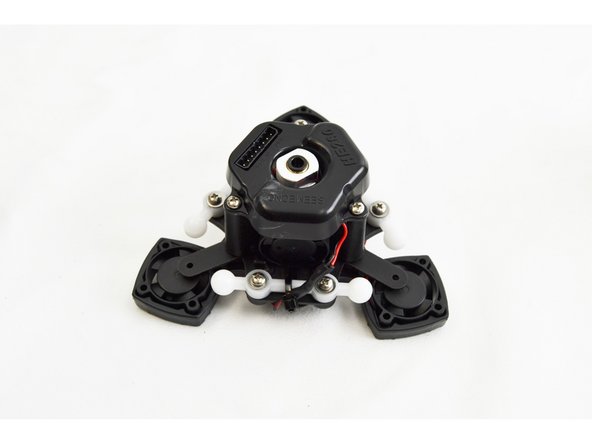
Locate the Top Cover HE280 Mount (71258) and (3) #4 x 3/8" sheet metal screws.
-
Orient the cover onto the top of the hot end assembly. There is only 1 orientation that will work.
-
Secure the cover with the #4 x 3/8" sheet metal screws.
-
Fully tighten, but do not over tighten.
-
-
-
Your HE280 Hotend is assembled and ready to print.
-
Please be sure NOT to lose the remaining plug that you have from the 25mm fan. You will be using this later in the build for the 40mm ball bearing fan that cools the RAMBo boards drivers.
-
If you have a REV6 accelerometer board, you didn't cut the fan lead of in this guide. Don't worry we though ahead and packed a fan lead in your RAMBo kit. You will find that later when you get to that step.
-


Cancel: I did not complete this guide.
39 other people completed this guide.
Attached Documents

11 Comments
Good instructions. There were a couple of minor things that I had to think about before I understood what I needed to do. If I had to build another hotend I’m pretty sure I could do it in 1/4th the time I did this one.
Dieter Weik - Resolved on Release Reply
I just bought a HE280 hotend upgrade kit to upgrade my Rostock Max V2. The kit doesn’t quite match the photos right now. There are a few differences; notably with the fan leads and the heater wiring, as others have mentioned. Also, the position of the thermistor solder holes is really unclear from the photo; the current PCB has two holes on the underside marked “TEMP”; I used those, assuming it’s correct.
Monte Krol - Resolved on Release Reply
Thank you Rick for your comment. Glad I read all the way through as I was wondering the same thing. Hopefully it works just plugging in the wires. I did have to get creative routing the leads to the fans. One end of the four fan connections was marked hot end so I put that one there. I was also short when it came to the tube that insulates the thermistor legs, another 20 mm would be nice, I used some of the leftover fiberglass insulated wire with the leads stripped out to make up the difference. When constructing the eight terminal plug in step 6 just go ahead and depress the catch in the rectangular hole above each of the wiring holes as suggested. Much easier to get it in there, especially for the little wires.
Adam Ruthford - Resolved on Release Reply
I just got done with my hot end build. Great instructions and a very nice unit. The only thing I noticed, a minute too late, was that I must have the latest version of the hotend pcb as it has plugins for all 3 part cooling fans. It’s too late for me, but I’m guessing I could have eliminated the whole cut,strip,and solder the fan leads step of the instructions. The light bulb in the brain turned on literally 10 seconds after I clipped the fan wires. If I’m correct in assuming all 3 can just be plugged right in, you may want to update the instructions. I can’t believe I missed that!!!!!
Rick
Rick Raffaelli - Resolved on Release Reply
The printer is working very well, but still I've had to disassemble the hot end several times now to clear clogs and replace the heater, which was not working. I'd suggest making the wiring between the hot end and the circuit board more modular - The circuit board is showing signs of wear from repeated resoldering, and it would have been great if I could have just unplugged the wires to the thermistor, the heater and the thermal fuse.
The hot end is by far the most difficult part of assembly, and along with the connectors on the RAMBO board are where I've found issues when I had to debug the build. Don't get me wrong - the printer is a beast once it is working, and I've had it running day and night for a month now. The only issues so far have been with wood filament which caused a nasty clog, but I was probably running the layers too fine (.1mm). No other failed prints, which I find amazing.
Seemecnc, you should consider integrating another Pluggable 8 position Push-In Wire Terminal Plug End its a !&&* attaching those wires, plus afterwards Im not sure if they are secure and making good contact.
Hector Quintanilla - Resolved on Release Reply
Read the comments and pretty sure most corrections noted have been updated. I had no problems except not seeing the fan wire tie channel and had to remove, rotate the fans one position and secure. I really dig this set-up, PDF / Vids plus updates. Nicely done. ~ Al 3D Printing Club 3DPC.tech
As I built this hot end the more I built the more I have become worried. if I have to service it to replace the theorister or the heater slug. That will be a major day of work. the screws that clamp the heater slug are facing up and unless you take the control board off you can not loosen these screws oh wait the board has wiring attached It's not going to move + all the elect. parts are soldered in. on my Robo R1 the hot end comes out by unclipping two wires and loosening one screw then move a swing out holder and the hot end is out . if you wanted to change the temp. wiring heater or Temp Gage. You can do that with the unit still in the printer. I bought this printer because when I saw it work it was great . I just don't know about the way this hot end is built it might be ok but right now I am unsure about how it will operate.
Jim Greene - Resolved on Release Reply
it was easy once i found all the parts. instructions were terrific...
john m barker - Resolved on Release Reply
just completed the hot end! great instructions! all to the exact measurement. suggest anyone following along pay attention to the measurements, Get out your caliper!
tyrell thomas - Resolved on Release Reply