
-
-
First, click here to read safety information . This safety information may be updated at anytime so occasionally check for updates.
-
NOTE: This guide is intended to be followed online in order to fully utilize the links and documentation found within.
-
Locate the components packs for your Rostock v3.2
-
If you are missing parts or have a defective component, please submit a support ticket through the link under the 'Support' tab on the SeeMeCNC website.
-
-
-
-
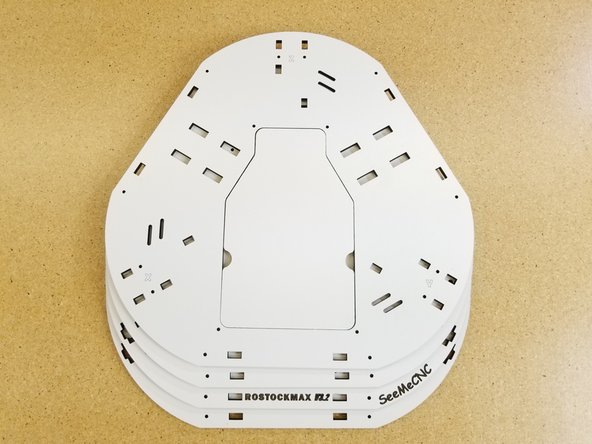
The first step in preparing for your build is to remove the masking from both sides of all laser cut panels. This masking helps protect the components during the cutting, packing, & shipping process.
-
Be careful not to accidentally discard smaller laser cut pieces.
-
You may want to clean the edges of the laser cut parts before peeling off the mask.
-
-
-
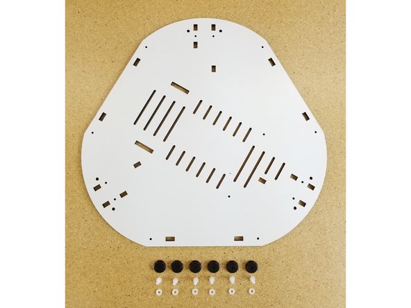
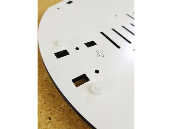
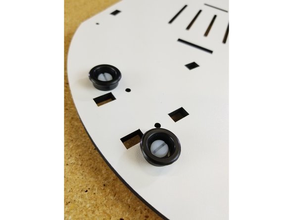
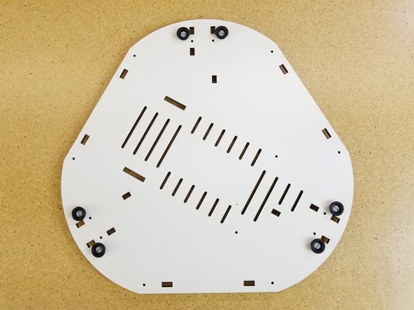
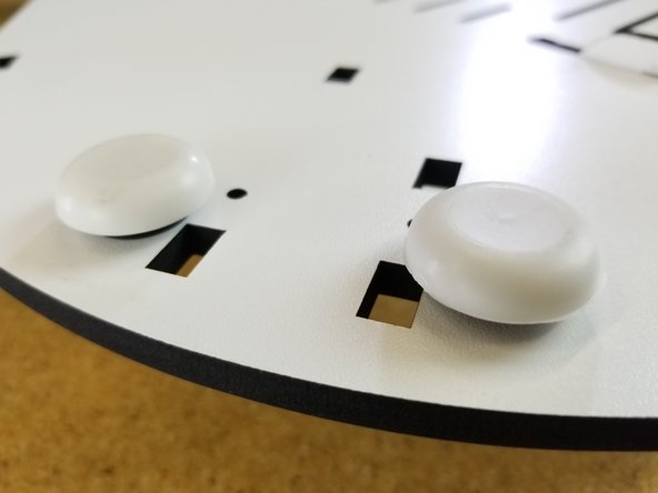
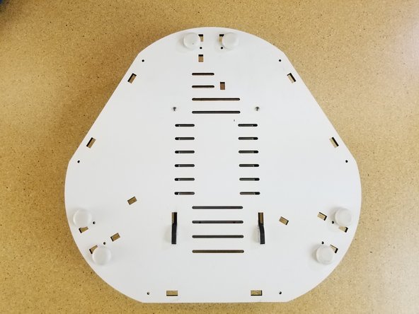
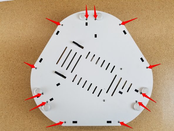
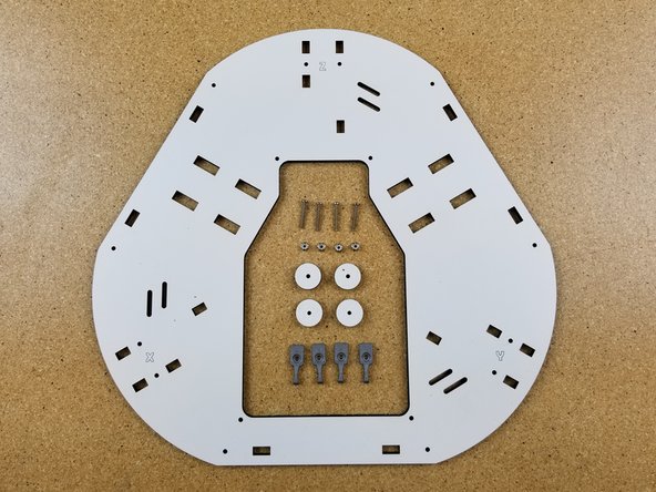
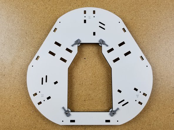
Install the feet on the base bottom plate. The feet install in the locations shown and should be on the opposite side of the plates identifying X Y & Z marks.
-
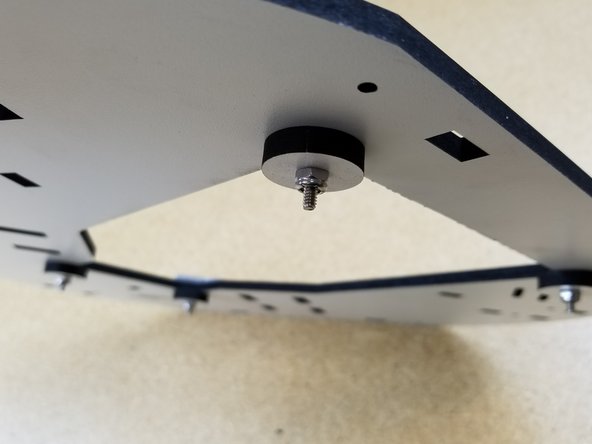
The feet are attached using the included plastic nuts and bolts. These fasteners are packed with the feet.
-
-
-
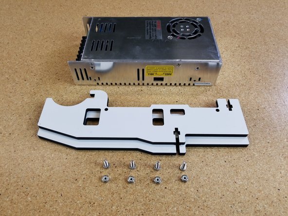
If your kit came with screws longer than 12mm, please email us at support@seemecnc.com. Some kits were packed incorrectly Feb to June 2018 with 16mm long screws. These will damage your power supply. We will ship replacement at no cost.
-
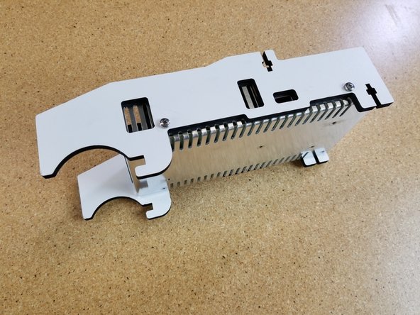
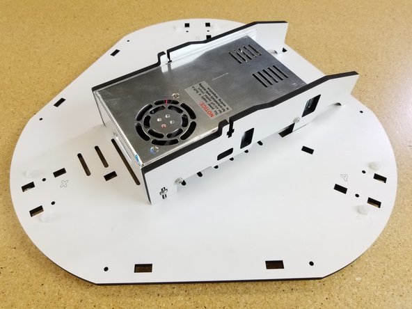
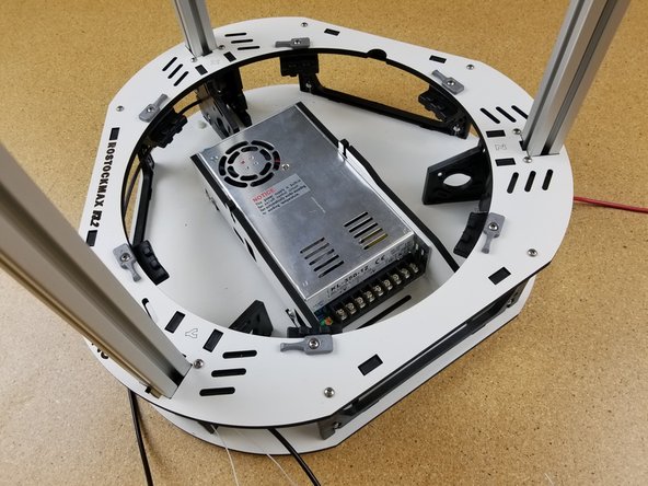
Locate the items shown
-
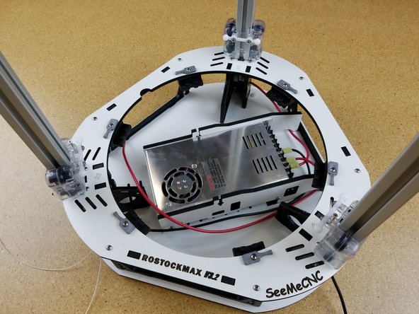
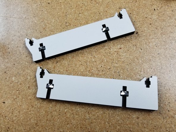
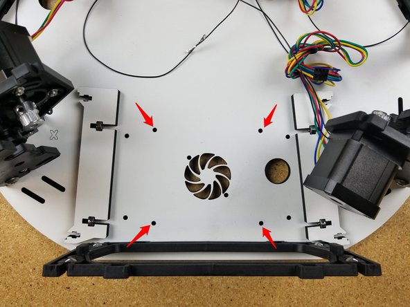
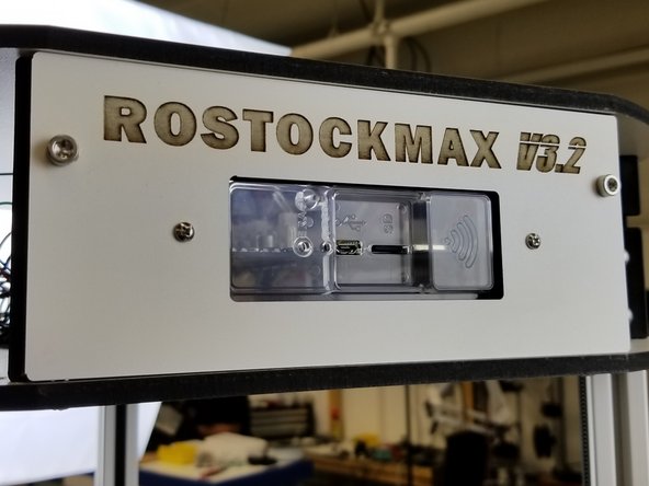
Install the PSU Blocker sides using (2) M4 x 12 per side. To ensure proper orientation, make sure that the voltage selector is visible through the "window" laser cut in the side of the blocker panel.
-
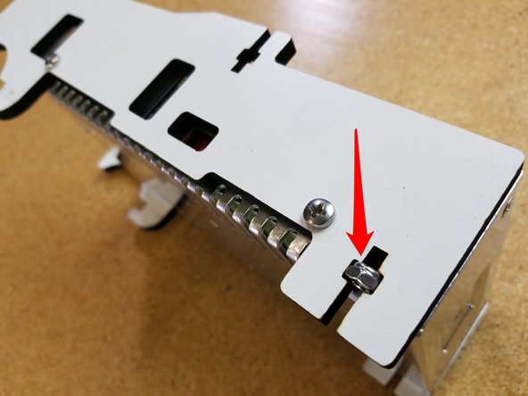
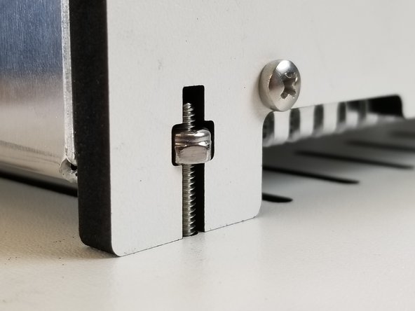
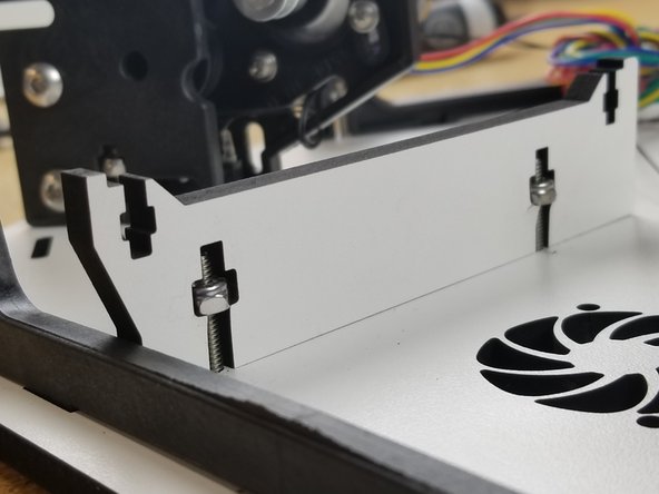
Slide (1) nylon lock nut in each of the T-Pockets as indicated with the red arrow.
-
-
-
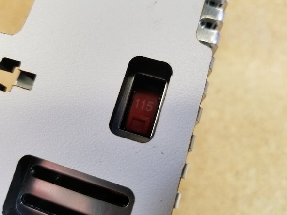
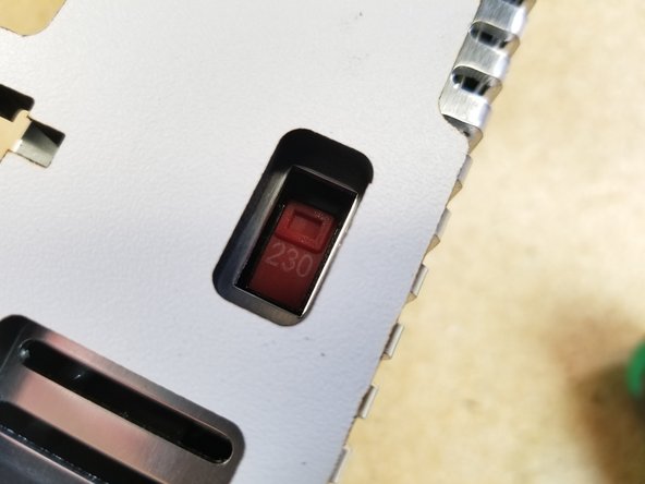
If you are located in the US, make sure the 220/110 switch is in the 110 (115) position, as indicated by the arrow. This defines the input voltage the power supply expects.
-
If you're in a country where 220v is the standard, make sure the switch is on the 220 setting.
-
-
-
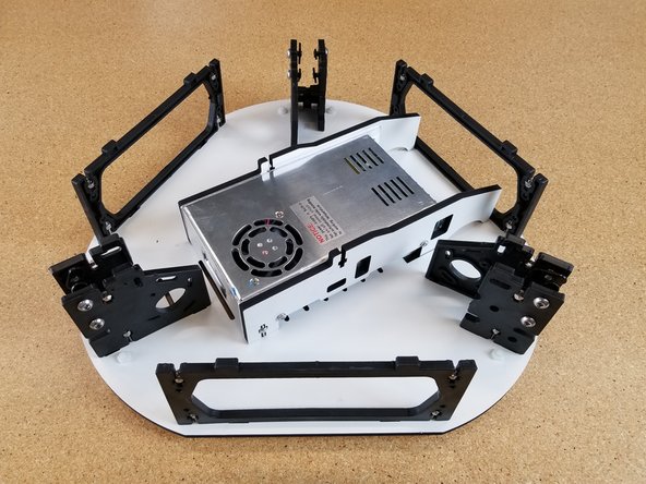
The PSU assembly installs into the base plate with (2) 6-32 x 1" screws. These screws will go into the nylon lock nuts you installed in the previous step.
-
The blocker panels will slide down into rectangular cuts in the base panel and then the whole assembly will slide and lock into place. You should then secure it with the (2) screws referenced above.
-
-
-
You'll be making three of these assemblies using injection molded parts 84407 & 84408 ( 1 each per assembly). This animation is an overview of the assembly. Before you begin, review the following steps. The next step will also cover this assembly and break it down in steps.
-
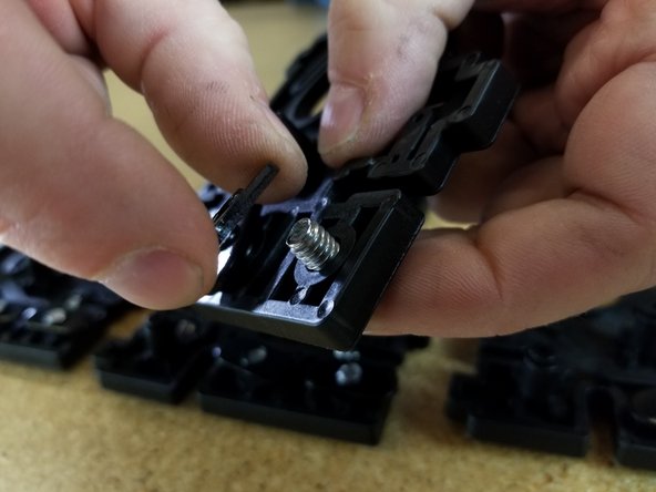
When inserting the nylon lock nuts, do so from the "inside" of the injection molded part. This will allow the nut to fit more easily into the nut pocket. Needle nose pliers make this a breeze.
-
Only thread the t-slot nuts on a few threads - you need to leave room for the tower channel to slide between the t-slot nut and the face of the injection molded mount.
-
The threads on the t-slot nuts have a flange on one side. The flanged side should be away from the head of the screw.
-
-
-
Insert the 6-32 nylon lock nuts into the injection molded parts first. There will be 2 of these nuts inserted per injection molded piece.
-
Then install the 1/4-20 button head screws and T-SLOT nuts. Remember to only get the nut started on the screw.
-
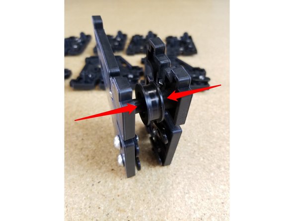
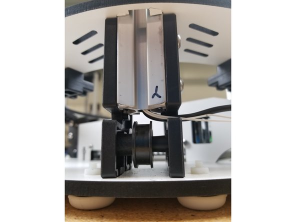
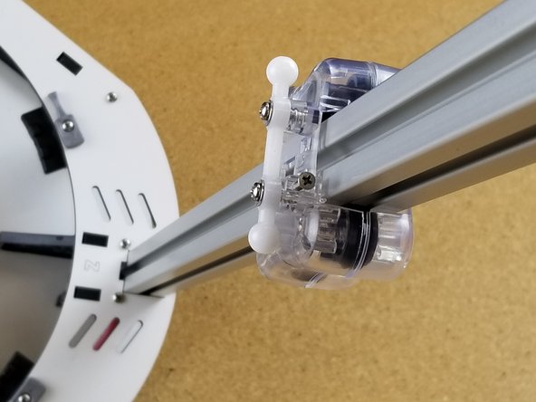
Press the bearing / cover assembly (pre-assembled by SeeMeCNC) onto the posts inline with the 1/4-20 hardware (position shown).
-
The two halves will be fastened together with #4 x 1/2"screws.
-
Complete 3 identical assemblies.
-
-
-
Do not Pre-Assemble the motor mounts yet. Use this animation as a reference only.
-
You'll need a #1 Phillips screwdriver in order to install the 2-56 screws used to fix the end-stop switches in place. Take care to not over-tighten the screws! The switch body is delicate and is easy to crush.
-
-
-
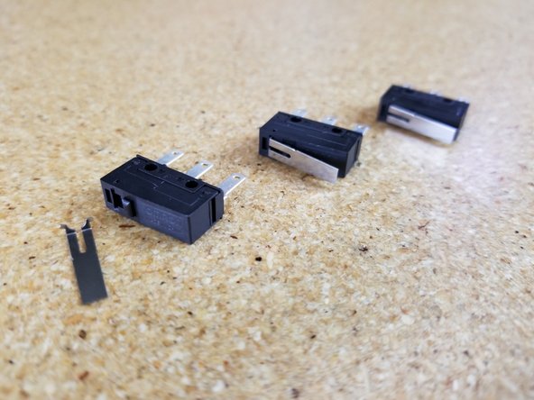
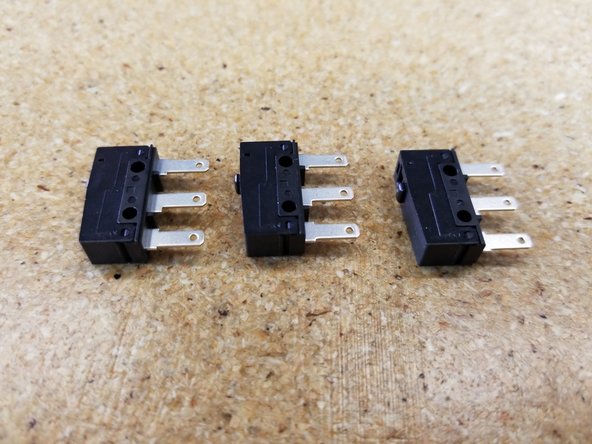
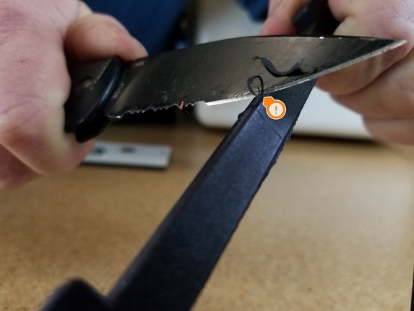
YOUR END STOP SWITCHES COME WITH A SMALL METAL ACTUATING LEVER, CAREFULLY REMOVE IT. IF YOU DON'T REMOVE THIS LEVER, YOUR MACHINE WILL NOT HOME OR WORK CORRECTLY.
-
-
-
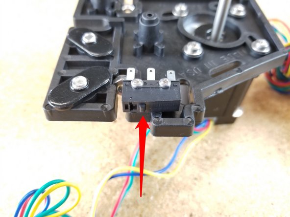
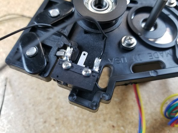
When installing the end stop switches, please make sure that they're oriented as shown in the photos. (The red arrow is indicating the "button" on the switch. It should be closest to the TSLOT hardware. Additionally, make sure that the endstop switches are level. This can best be done by pushing them up or down as you tighten the screws.
-
First install the end stop switches. You'll need a #1 Phillips screwdriver in order to install the 2-56 screws used to fix the end-stop switches in place. Take care to not over-tighten the screws! The switch body is delicate and is easy to crush. The holes are not tapped/thread.
-
Insert the 6-32 nylon lock nuts into their pockets. (2 per injection molded piece).
-
Next install the stepper motors using (4) M3 x 10mm screws and washers. Do not tighten these screws. The stepper motor pivots to allow for tensioning the belts (completed later)
-
Install the TSLOT hardware. Remember to only start the 1/4-20 button head screws into the TSLOT nuts.
-
Install two bearing / cover assemblies per injection molded plate. (this is different than the base assembly which only used 1 bearing / cover assembly per plate)
-
If you've reached this point and the little metal lever arms are still on your end stop switches, REMOVE THEM RIGHT NOW. Carefully mind you, but REMOVE THEM.
-
-
-
Locate the bag of black 26awg wires. These are your end-stop wires.
-
One end of each wire is terminated with a KK style terminal. You will solder the other end to the end-stop.
-
2 wires will be soldered to each end-stop switch. Solder the wires to the outer two legs (nothing gets soldered to the middle leg).
-
For those wondering why soldering the end-stop wires was not completed previous to installing the end-stops, it is merely a personal preference. Having them installed on the motor mounts gives the assembly some mass, so they don't move around when soldering.
-
-
-
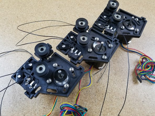
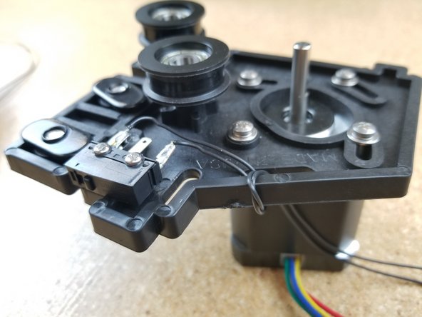
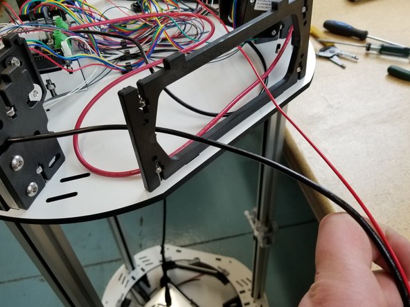
This is not required, but looping the wires through this plate will act as a strain relief and help manage the wires.
-
-
-
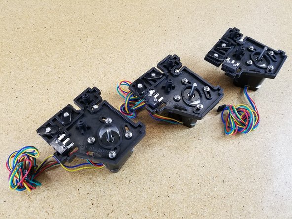
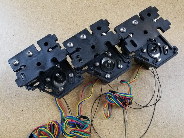
Now complete the 3 motor mount assemblies the same way you completed the idler mount assemblies.
-
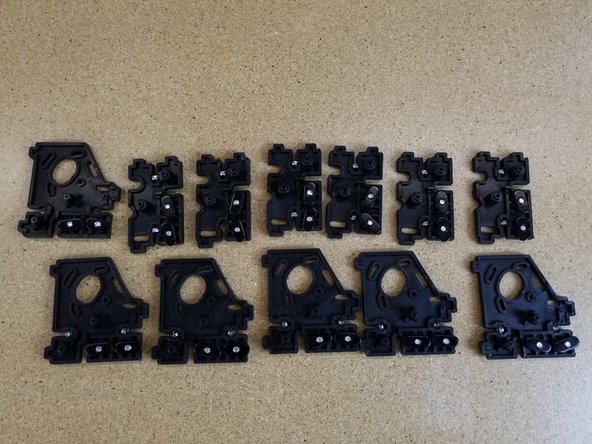
You should now have 3 completed motor mount assemblies and 3 completed idler mount assemblies.
-
-
-
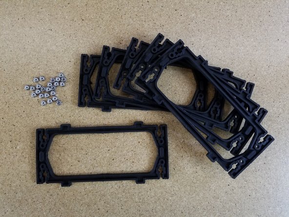
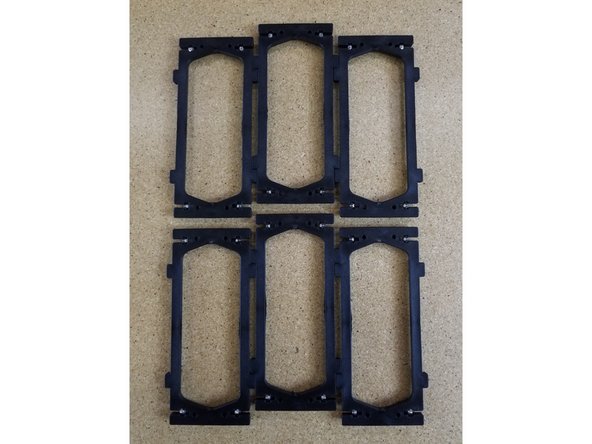
Insert nylon lock nuts into the side plates (as done in previous steps). You will use a total of (24) nylon lock nuts.
-
You will need to CAREFULLY remove any flashing on the molded parts (if necessary) to ensure they install properly later.
-
-
-
You will now install the 3 idler assembles on the base plate. These are the assembles WITHOUT the motors.
-
Install the 3 side panels with the smooth side facing OUT, as shown in the photo.
-
Tabs in the plates of the assembly align with cutouts in the base plate. Press the assembly into these cutouts.
-
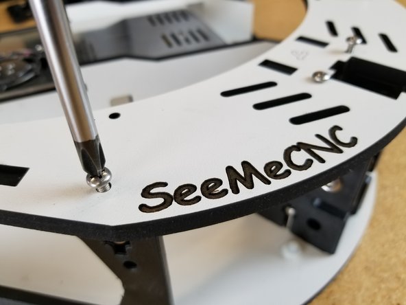
You will secure each assembly with (2) 6-32 x 1" screws. This may be done easiest by cantilevering the base plate over the edge of a table. After you have all (6) screws started you can flip the assembly over and fully tighten.
-
-
-
You are now ready to install the base top plate on the base assembly.
-
Start in one area and align the tabs in the injection molded components with the cutouts in the laser cut plate. When aligned press down and continue to work your way around the plate until it is fully seated on the injection molded components.
-
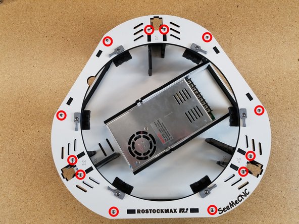
Finish by securing the plate with (12) 6-32 x 1" screws. Fully tighten these screws.
-
-
-
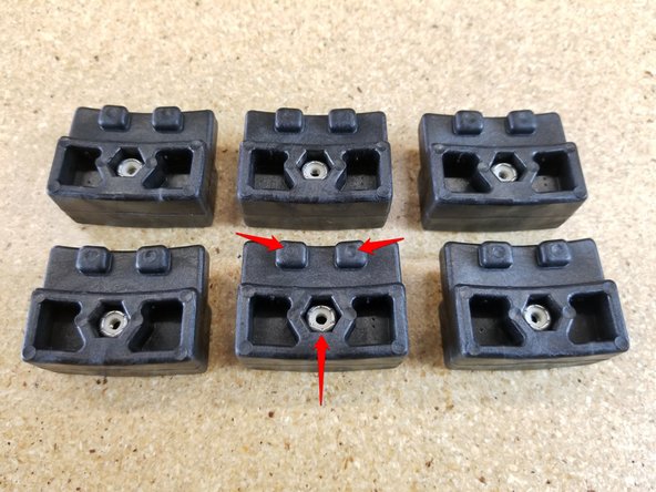
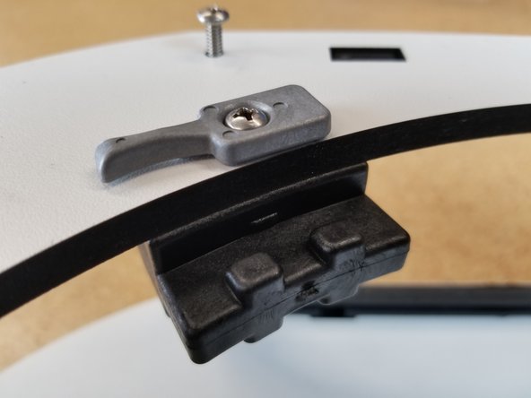
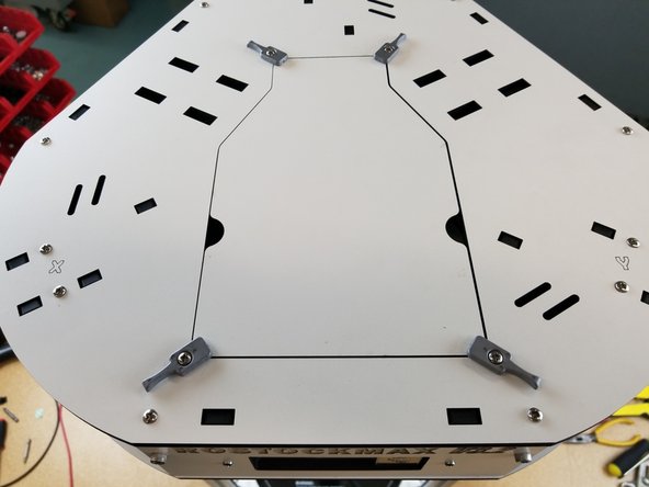
Insert stainless steel nylon lock-nuts into the side with circular marks.
-
Using 6-32 x 1" phillips pan head machine screws, gently tighten as shown. The bed clamps should rotate easily, but not be loose.
-
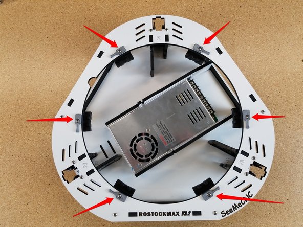
You will be installing 6 bed clamps and support blocks around the periphery of the hole in the center of the laser cut plate.
-
-
-
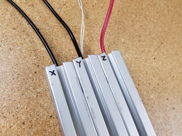
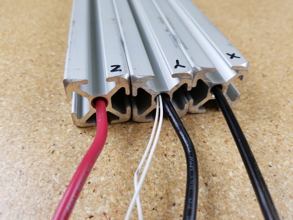
Locate the (3) pieces of T-Slot, (2) white 26awg thermistor wires, and long (3) 12awg red/black wires.
-
Label the towers X Y & Z
-
The Z tower will get the red 12awg wire fed down the center hole.
-
The X tower will get a black 12awg wire fed down the center hole.
-
The Y tower will get the two thermistor wires and a black 12awg wire fed down the center hole. On this tower it is easiest to feed the thermistor wires first and then chase them with the 12awg black wire.
-
-
-
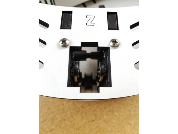
We will start with installing the Z tower in the base assembly. You will start by aligning the T-Slot Nuts in the motor mount assembly so that are all in a vertical orientation as shown. '
-
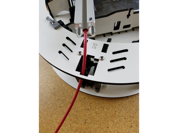
Next you will feed the 12awg wire down through the melamine plate.
-
Insert the extrusion into the base top plate, and then through each set of the TSLOT hardware. You will need to have the TSLOT nuts in a vertical orientation to be accepted by the extrusion. You also may need to loosen the TSLOT nuts if you have them too tight.
-
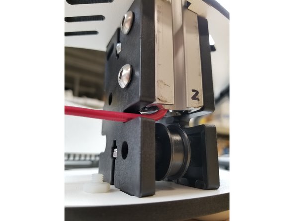
You should not force the extrusion into the assembly. Be careful while working the extrusion down into the plate and through the TSLOT hardware. Too much side-to-side motion can fracture the base plate.
-
Upon seating the extrusion, you should route the wires around the idler plate as shown and tighten the (4)1/4-20 button head screws.
-
-
-
You will now install the remaining two towers just as you did the Z tower. Begin with the Y tower, which has the white thermistor wires run through the center hole.
-
-
-
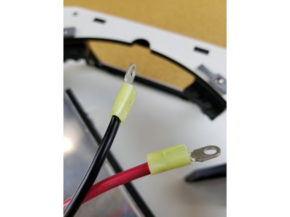
Locate the yellow ring terminals
-
You will crimp a yellow ring terminal on the red 12awg wire from the Z tower, and the black 12awg wire from the X tower.
-
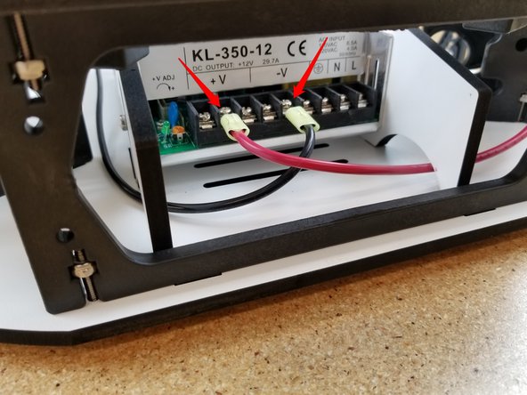
These two wires should then be routed through the base to the power supply.
-
They will connect to vacant V+ (red wire) and the V- (black wire) terminals on the power supply using the screws provided with the power supply.
-
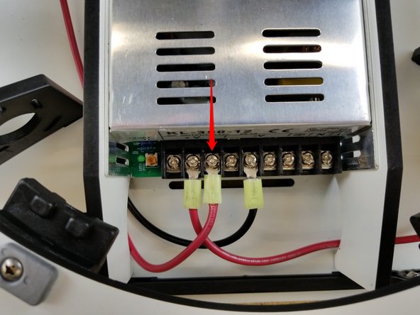
Locate the shorter length of 12awg red wire from your kit. Crimp the final yellow ring terminal on one end of this wire. It will connect to the V+ location indicated in the photo on the power supply.
-
-
-
You will need to assemble the three carriages for this step. Please open this link to the guide in a new window, and return here when you're finished: Carriage Assembly
-
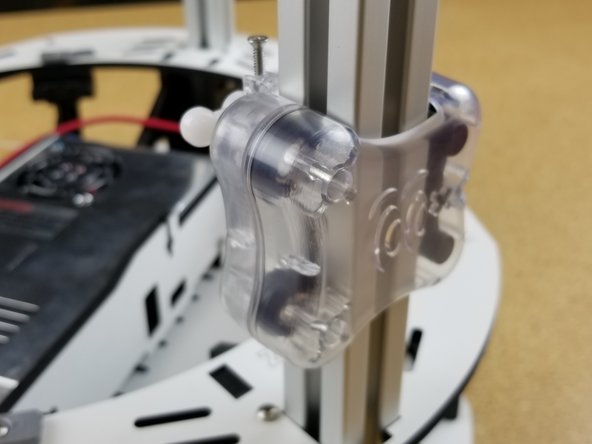
We will now install the injection molded carriages on the three towers. They will install on the towers with the ball joints facing the inside.
-
To install the carriages pass the wires from the top of the TSLOT through the center of the carriage.
-
Pushing the carriage down too hard too fast can damage the bearing covers on the carriages. Please perform this operation slowly and carefully.
-
Lower the carriage down to the top of the TSLOT and then slowly push it down onto the TSLOT.
-
-
-
We will now build up the upper assembly. You will need the motor mount assemblies you previously built and the upper assembly base plate.
-
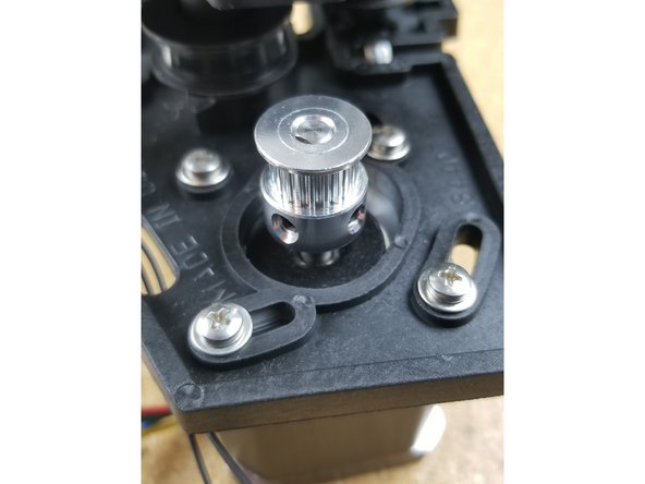
Install the timing pulleys on the motor shafts with the set screw up against the flat, as shown in the photo.
-
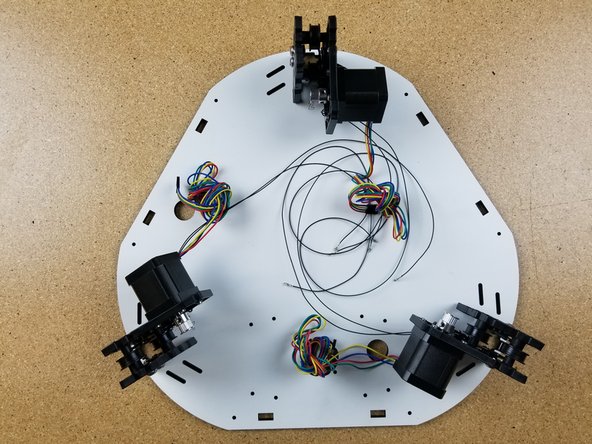
The upper assembly base plate has laser cut engraving on it that indicate the X, Y, and Z tower locations. Be sure to put that faced up towards you and away from your work surface.
-
As you did with the base assembly, orient and install the motor mount assemblies. Secure with 6-32 x 1" screws.
-
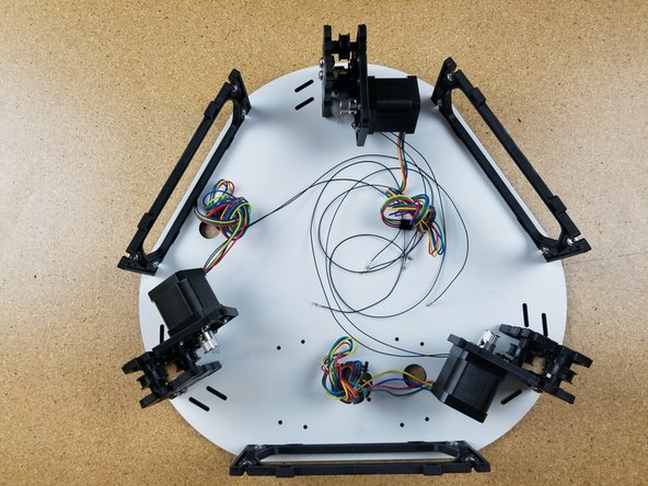
Repeat the process to install the injection molded side panels.
-
-
-
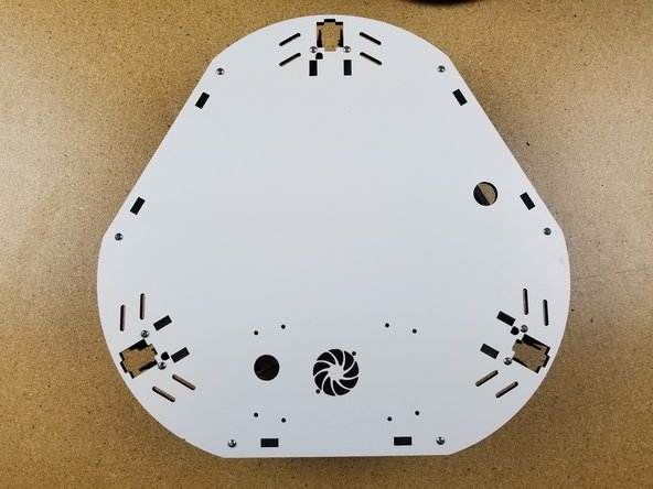
You can flip the assembly over and fully tighten all 6-32 x 1" screws.
-
While flipped over, ensure that the laser engraved X, Y, and Z indicators are facing your work surface.
-
-
-
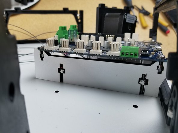
The Duet WiFi board mounts to the upper assembly using the laser cut mounts pictured. They will be secured to the upper assembly base plate with four 1" 6/32 Pan head screws and nylon lock nuts in the locations shown.
-
Install the board mounts so that the angled ledge hangs over the side panel. They should only install one direction.
-
-
-
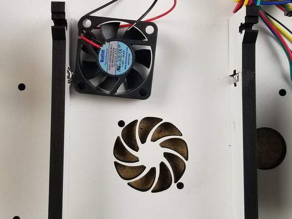
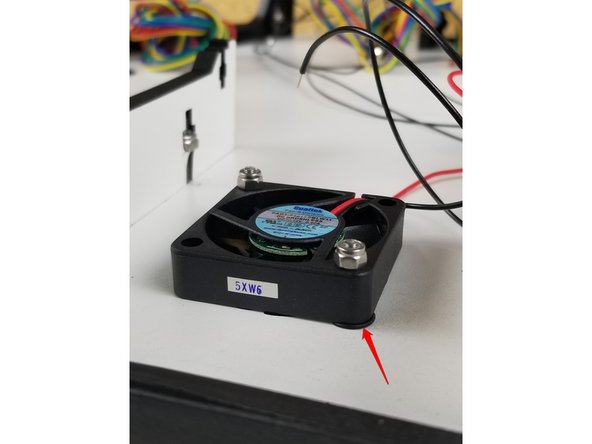
The 40mm fan gets installed under the Duet WiFi board using (2) M3 22mm socket head bolts, (2) rubber o-rings, and (2) nylon lock nuts.
-
Be sure the fan is blowing UP toward where the board will be mounted.
-
The o-ring should be installed between the fan and the laser cut panel.
-
-
-
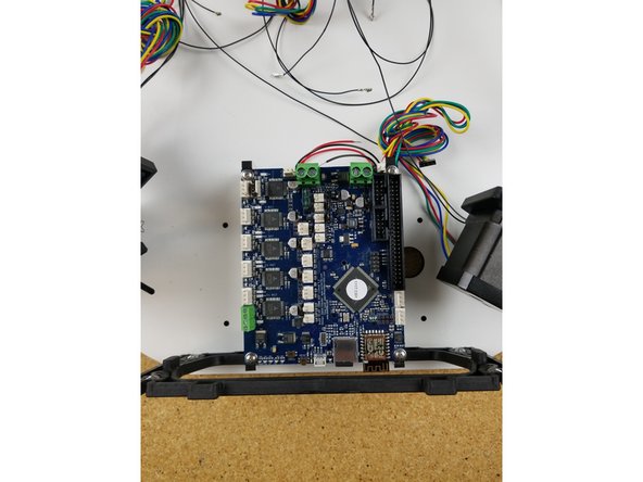
Install the Duet as shown, using the M3 10mm screws and M3 nylon lock nuts.
-
-
-
Installing the upper assembly begins with aligning the assembly with the base assembly (X Y & Z).
-
You will have to first pass the wires up through the holes in the plate of the base assembly.
-
Then you can align the holes for the TSLOT with the TSLOT
-
-
-
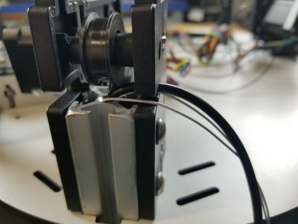
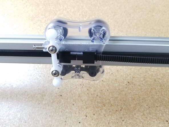
Routing the belts is best completed by laying the machine down on its side.
-
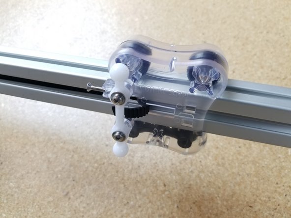
Begin by routing the belt through the top side of the carriage as shown in the first image.
-
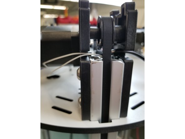
Install a belt clip. The two wider stanced legs will insert into the carriage first and then the belt clip can be pressed down to lock into place. If it is not wanting to lock, you may need to apply inward pressure on the closer stanced legs while pushing down to lock it in place.
-
-
-
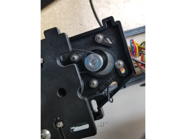
Rotate the stepper motor to the position shown in the photo. This location will give you the most available range of motion for tightening the belts after they are installed.
-
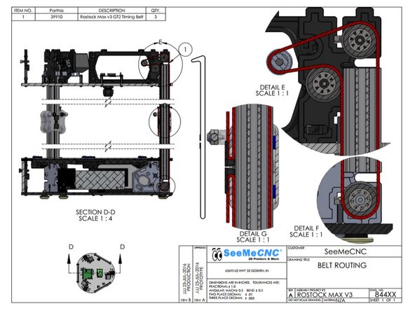
Route the belt as shown in the diagram on step 31
-
Be sure that the belt is not routed on the outside of the frame or carriage pieces! This will prevent motion.
-
To thread the belt ends into the carriage, use a wire tie or the cut-off from a wire tie to guide the belt up into the belt slot.
-
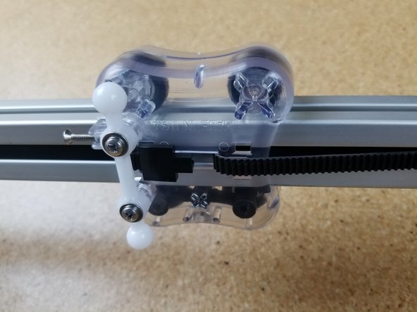
After you have threaded the belt into the carriage pull the belt end tight - you want to pull all the slack out of the belt.
-
Install the second belt clamp
-
You can trim excess belt, but leave approximately 1" past the belt clip.
-
Complete the routing process for the remaining two towers.
-
-
-
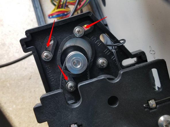
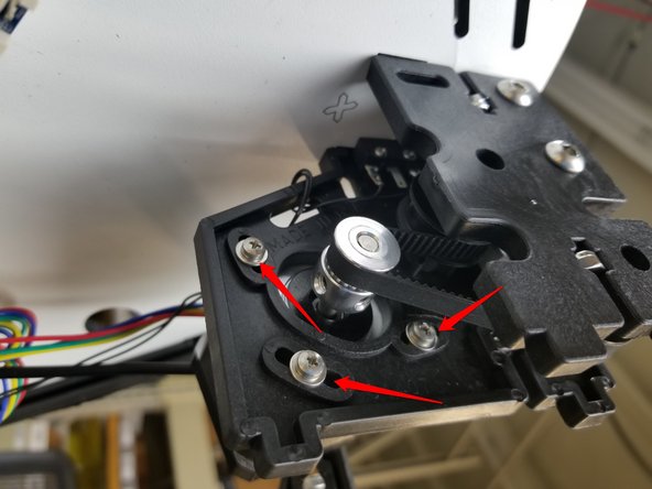
Tension the belts by rotating the motors to pull the belt tighter. While holding the motor in place, tighten the motor screws so the belt tension is locked in to place.
-
The belts should be tight enough that they don't skip teeth on the pulleys, but not so tight that they cause too much strain to themselves or the motor shaft.
-
-
-
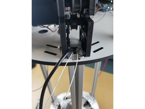
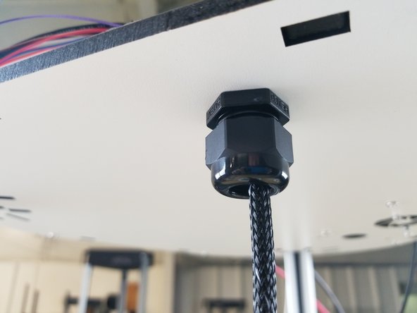
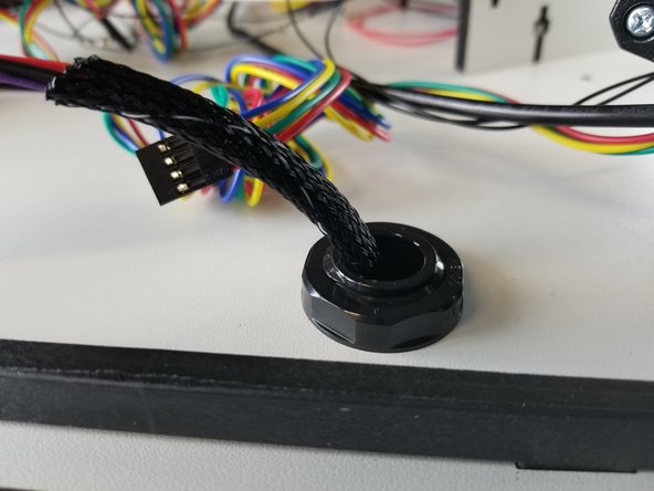
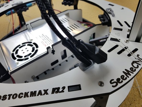
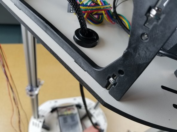
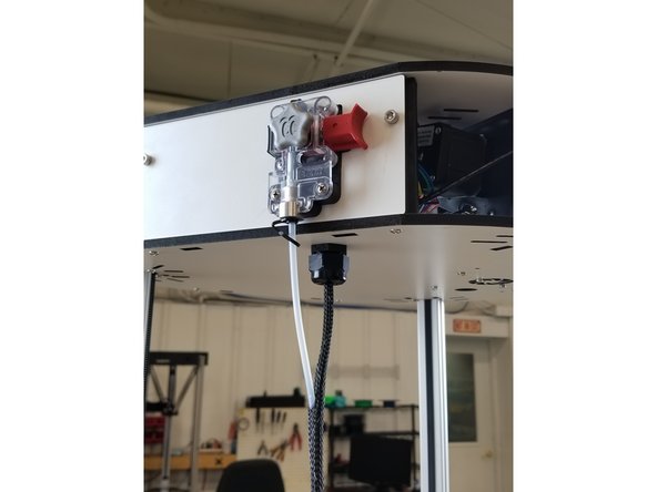
The Cable Mount Hub (Strain Relief) gets installed in a hole in the top base plate. There are (2) parts, the hub and the nut to secure it.
-
After installation, you will feed the hot end whip (end without connectors) up from the bottom through the strain relief. Do not tighten at this time.
-
-
-
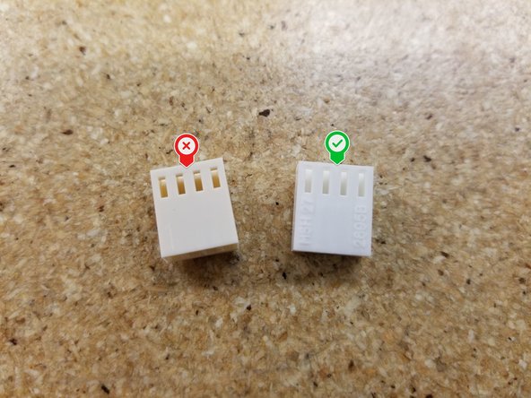
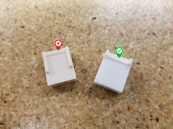
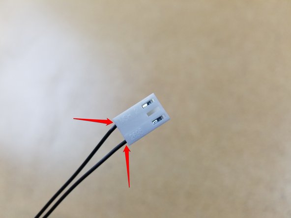
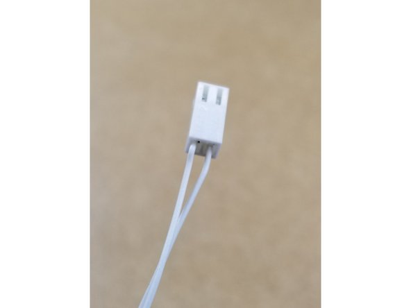
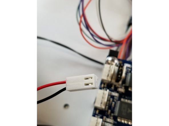
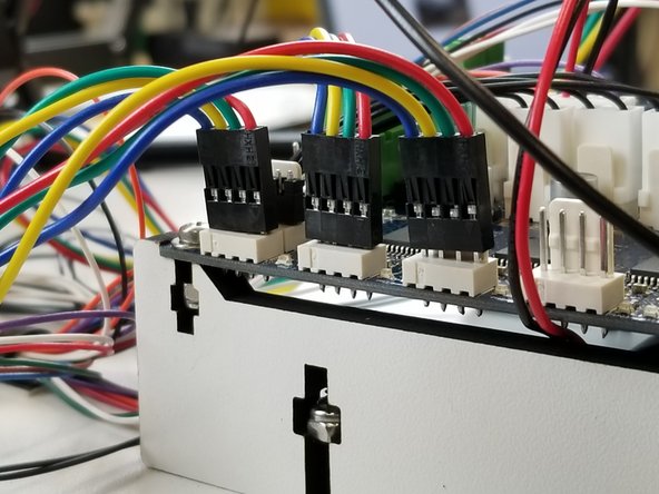
When inserting the wires in the white Molex KK connectors, make sure you're using the connectors we sent you in the kit, NOT the ones included in the Duet box!
-
The CORRECT connectors will be a whiter color, with text on them and shorter tabs on the clip side. See photos for reference!
-
-
-
You will now need to set the whip length and tighten the cable mount hub.
-
Pull the end of the whip all the way to the bed of the printer and touch the bed clamp closest to the Y tower.
-
You will tighten the cable mount hub at that position so the whip's length is fixed.
-
-
-
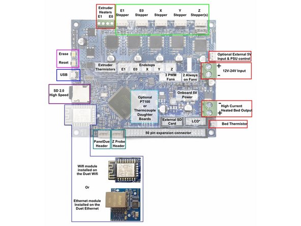
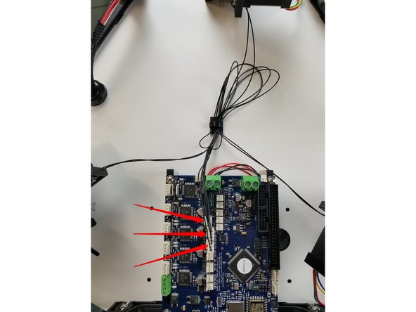
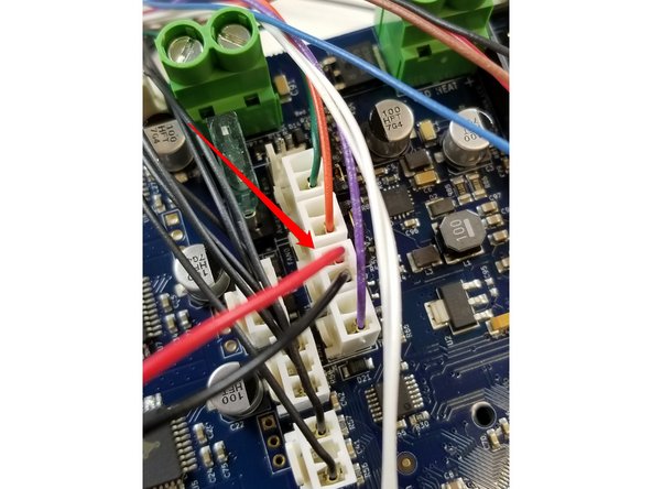
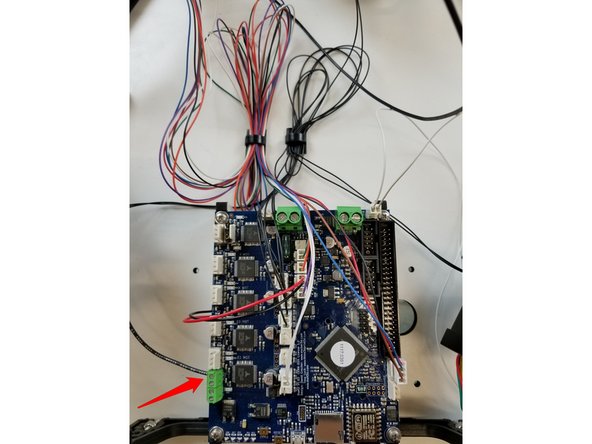
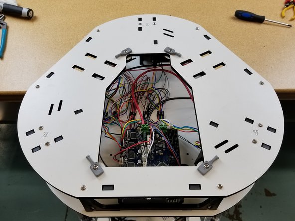
Image one shows the common terminal locations on the Duet board. Please reference this when preparing for wire installations.
-
When inserting the wires in the white Molex KK connectors, make sure you're using the connectors we sent you in the kit, NOT the ones included in the Duet box!
-
We will begin with the end-stop switches. You will need to install three pin KK terminal housings on each set of end stop wires. The wires will install in terminals 1 & 3.
-
You will then plug them into the Duet Board. You must ensure that you get the correct end-stop plugged in with the corresponding location on the Duet Board. If not we will run into issues during later setup.
-
You will then secure the end-stop wires with a cable tie.
-
-
-
You will need to install KK connector housings on the whip wires first. Be sure that the whip is already fed through the cable mount hub!
-
When inserting the wires in the white Molex KK connectors, make sure you're using the connectors we sent you in the kit, NOT the ones included in the Duet box!
-
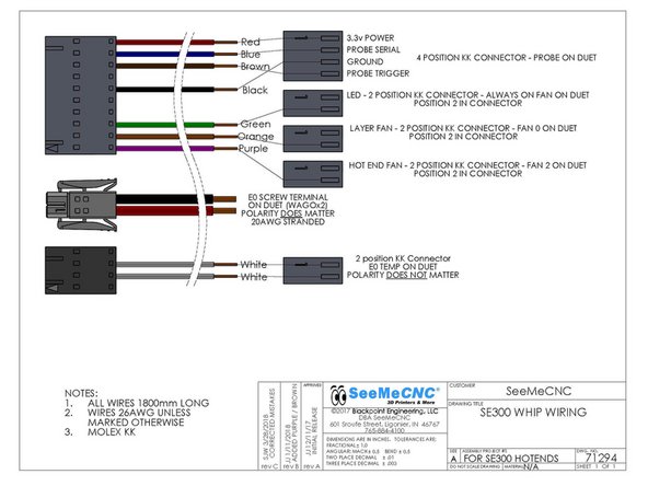
LED: Green Wire - 2 pin KK connector - PIN 2
-
HE FAN: Purple Wire - 2 pin KK connector - PIN 2
-
LAYER FAN: Orange Wire - 2 pin KK connector - PIN 2
-
PROBE: Red PIN 1, Blue PIN 2, Black PIN 3, White Wire PIN 4 - 4 pin KK connector
-
E0 TEMP: 2 White Wires - 2 pin KK connector - PINS 1 & 2 (Polarity DOES NOT matter)
-
-
-
Install E0 TEMP (2 white wires in a 2 pin connector) connector in the location E0 TEMP position on the DUET board.
-
Install the HOT END FAN (1 purple wire in a 2 pin connector) connector in the FAN 2 position on the DUET board.
-
Install the LAYER FAN (1 orange wire in a 2 pin connector) connector in the FAN 0 position on the DUET board.
-
Install the LED (1 green wire in a 2 pin connector) connector in the Always On Fan position on the Duet board.
-
Install the PROBE Wires(red, blue, black and brown wires in a 4 pin connector) connector in the PROBE position on the Duet board.
-
-
-
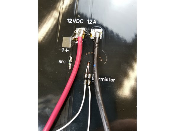
The Y tower has the 12awg black wires and (2) white thermistor wires.
-
You will want to route those wires as shown. Install a two position terminal housing on the white wires and plug that into Bed Temp. The negative lead for the bed will not get hooked up to anything yet. Later we will connect that wire to a fuse holder.
-
-
-
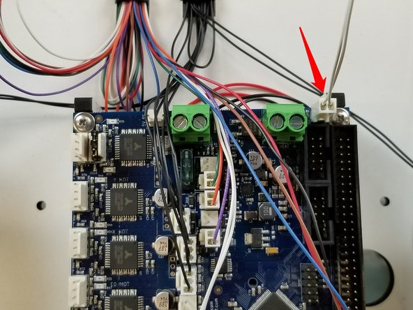
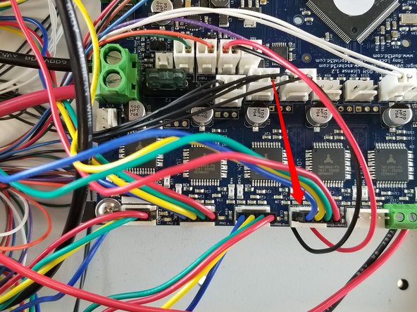
Crimp KK connectors on the Duet fan wires, and install them in a two pin connector as shown.
-
Plug the fan in at the location indicated in the photo.
-
The black 20awg wire from the hotend whip can now be attached to the terminal block as indicated in the photo. You may need to rotate the screw counter clockwise before inserting the wire to open the terminal, as it may be closed from the factory.
-
Make sure the green terminal block DOES NOT twist, it could rip off and cause you to replace your entire Duet! You may need to CAREFULLY hold it with pliers while tightening the screw.
-
-
-
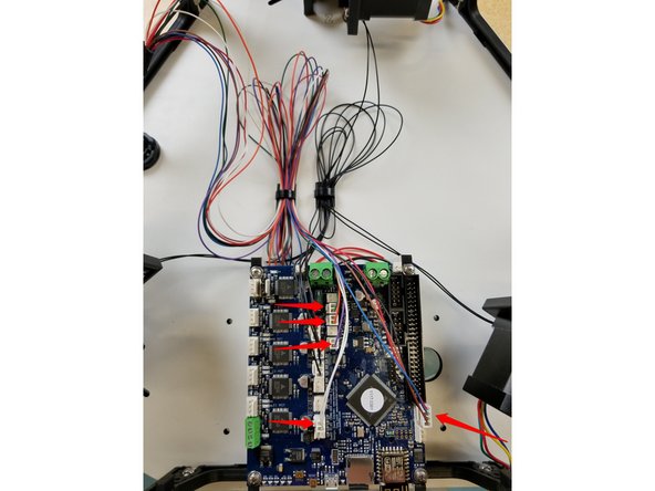
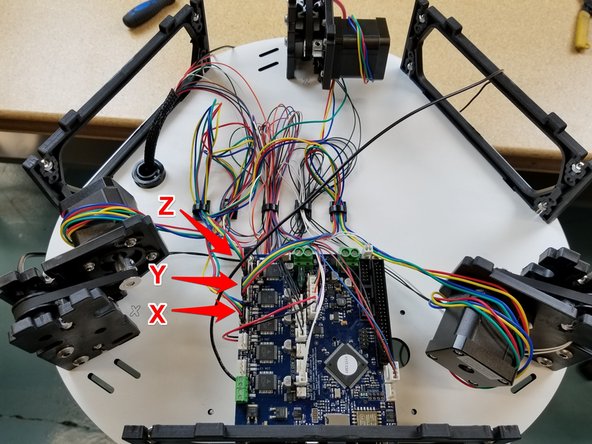
Install the motor wires in the locations indicated here.
-
Make sure the motor connectors are facing the proper direction, with the red wire facing the front of the machine.
-
-
-
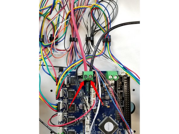
Now install the black 12awg wire from the X tower, and the red 12awg wire from the Z tower in the locations indicated here.
-
Make sure the green terminal block DOES NOT twist, it could rip off and cause you to replace your entire Duet! You may need to CAREFULLY hold it with pliers while tightening the screw.
-
-
-
NOTE: If you purchased a machine after 8/22/2018 you will not need to install the 5A or 15A fuses. Your kit may not come with them, and will come with a blank side panel instead. The fuses are now built in to the Duet board. If this is the case, skip this step, we'll revisit this later in Step 50.
-
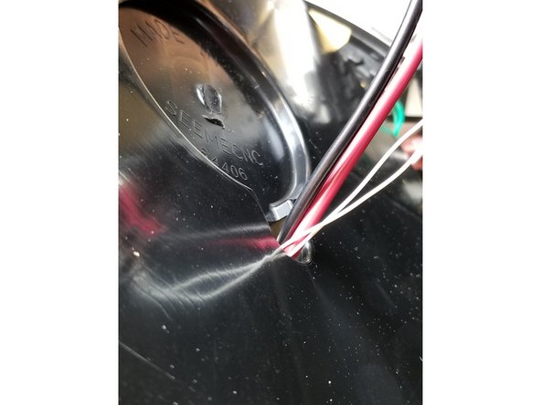
At this stage, pass the red 20awg wire from the hotend whip and the black 12awg wire from the Y tower through the frame panel between the Y and Z towers. We will return to this in a few steps.
-
-
-
Locate the top plate pieces shown.
-
Install the hatch clips as shown using the6/32 1" bolts and nylon lock nuts.
-
-
-
Install the top plate the same way the other main frame plates have been installed, using the 6/32 1" bolts and captive nylon lock nuts in the motor and side panel plastics.
-
-
-
NOTE: If you purchased a machine after 8/22/2018 you will not need to install the 5A or 15A fuses. Your kit may not come with them, and will come with a blank side panel instead. The fuses are now built in to the Duet board. If this is the case, skip this step, we'll revisit this later in Step 50.
-
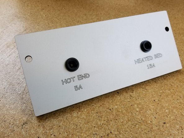
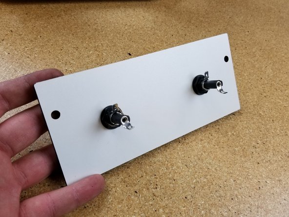
Install the fuse holders as shown.
-
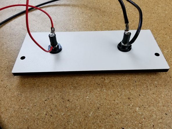
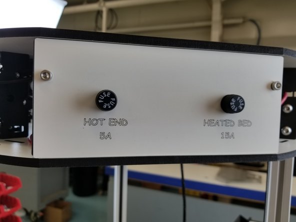
Solder the 20awg red wire from the hotend and the extra short length of 18awg red wire in your kit to the HOT END 5A fuse holder location, indicated by the COMIC SANS laser etched into the wood.
-
Solder the 12awg black wire from the Y tower and the extra short length of 12awg black wire in your kit to the HEATED BED 15A fuse holder location, indicated by the typeface that's been out of style since the 90s.
-
-
-
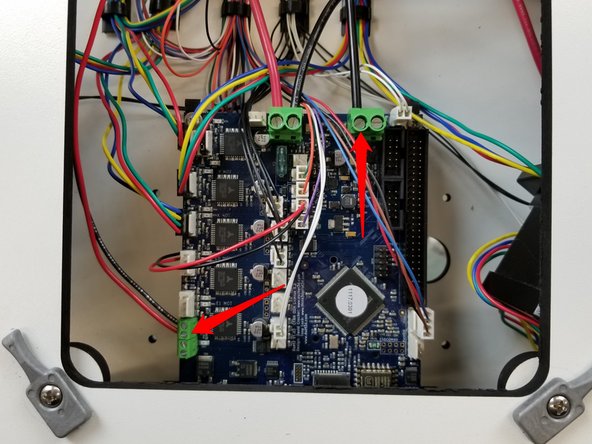
Install the wires coming from the fuses in the locations indicated in the photo.
-
NOTE: If you purchased a machine after 8/22/2018 you will not need to install the 5A or 15A fuses. Connect the 20awg red wire from the hotend whip and the 12awg black wire from the tower directly to the green terminals indicated in the photo.
-
Make sure the green terminal block DOES NOT twist, it could rip off and cause you to replace your entire Duet! You may need to CAREFULLY hold it with pliers while tightening the screw.
-
Install the 5A and 15A fuses in their respective locations, and install the fuse plate using the SHCS 10/32 cap screws.
-
-
-
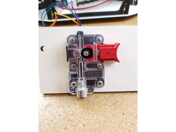
Install the EZR Struder as shown, using four M3 10mm screws to attach it to the motor, and two 6/32 1" bolts and nylon lock nuts to attach it to the side panel.
-
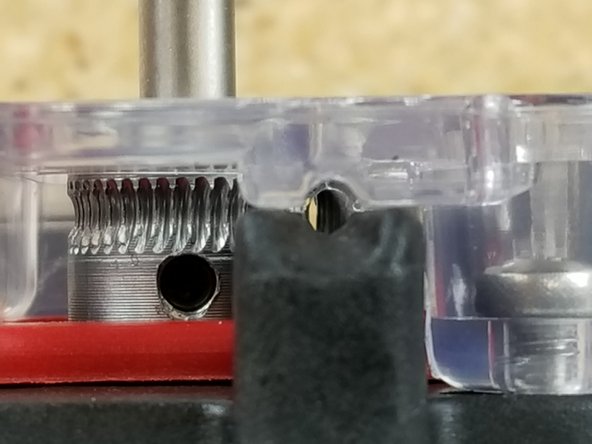
Slide the hobbed drive roller on the motor shaft. Align the curve of the gear teeth with the bearing in the EZR and tighten the set screw.
-
In this instance, do NOT align the set screw with the flat of the motor shaft. The flat does not go low enough to meet the set screw fully. Tighten the set screw on a blank area of the curve of the shaft.
-
You can now install the silver knob.
-
-
-
Install the EZR plate using the SHCS 10/32 cap screws on the side panel between the X and Z towers.
-
Plug in the extruder motor the same way you did with the motors, in the next available position on the Duet.
-
-
-
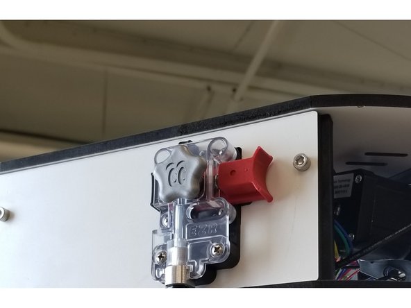
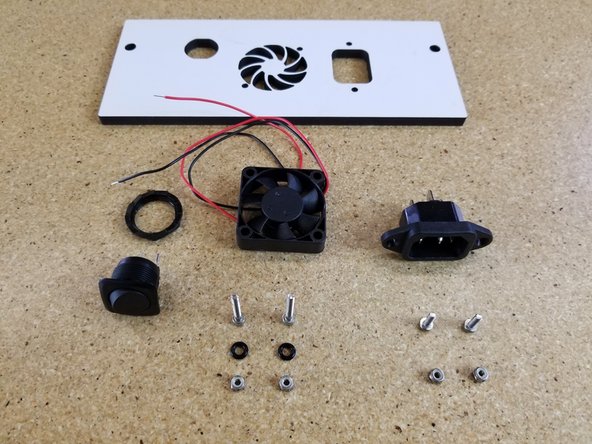
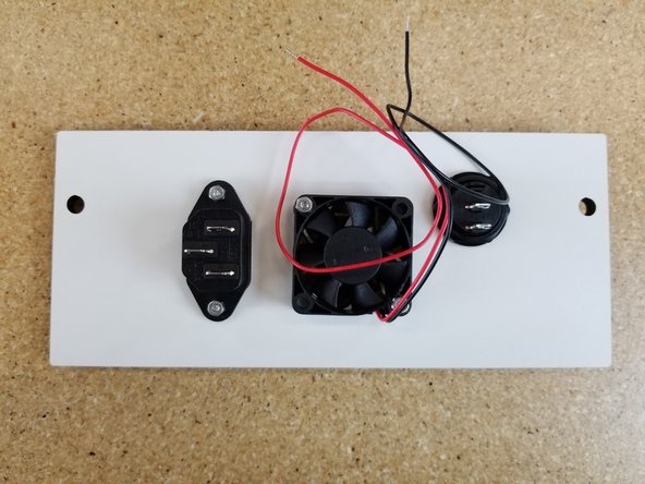
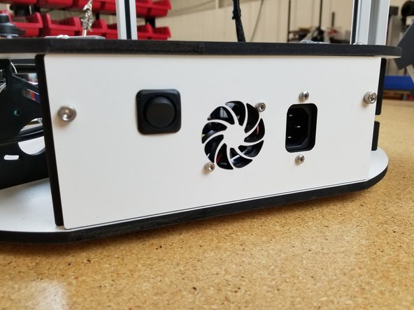
Install the rocker switch and IEC Plug on the plate shown, in the orientation shown.
-
The rocker switch comes with a nut to secure it to the plate.
-
The IEC Plug is installed using (2) M3 x 14mm long screws and (2) Nylon Lock Nuts.
-
-
-
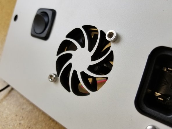
The fan should be installed so that it will blow OUT through the panel. (The foil sticker is should be facing towards the laser cut panel)
-
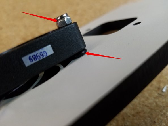
It is attached to the laser cut plate using (2) M3 22mm socket head bolts, (2) rubber o-rings, and (2) nylon lock nuts.
-
The o-ring is installed between the fan and the laser cut plate.
-
-
-
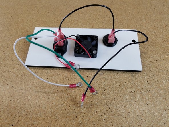
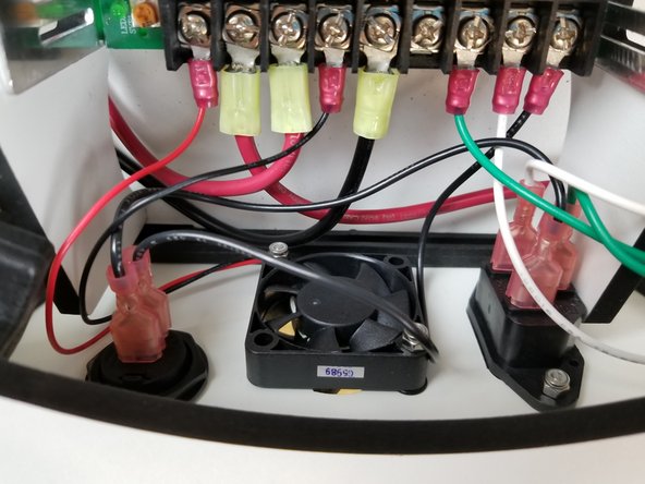
Locate the 18awg green, white, and black wires shown.
-
You will crimp spade connectors on both ends of the shorter 18awg black wire.
-
On the remaining green, white, and black 18awg wires, you will crimp a spade connector on one end and a small (red) ring terminal on the other end.
-
You will then connect the wires to the plug and switch. The IEC plug is labeled with L, N, and ground symbol. The short black wire (with (2) spade connectors) will go to L, The white wire will go to N, and the Green wire will go to ground.
-
The short black wire with (2) spade connectors will go to the rocker switch (tab does not matter).
-
The longer black wire will connect to the remaining tab on the rocker switch.
-
With the remaining red ring terminals, you will crimp them onto the 60mm fan leads.
-
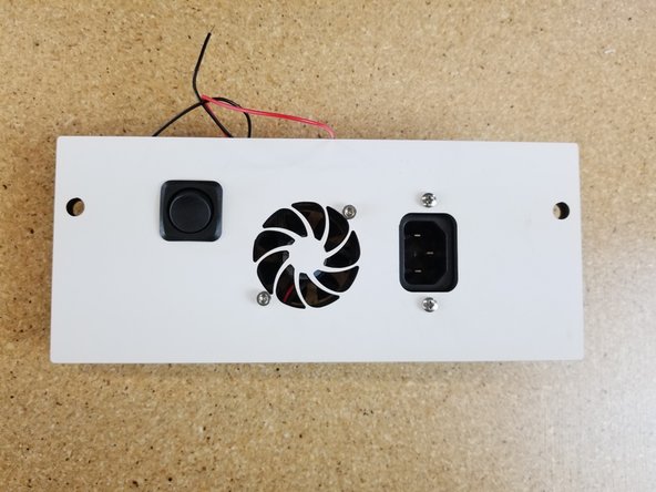
Your completed assembly should look similar to that of the photo.
-
-
-
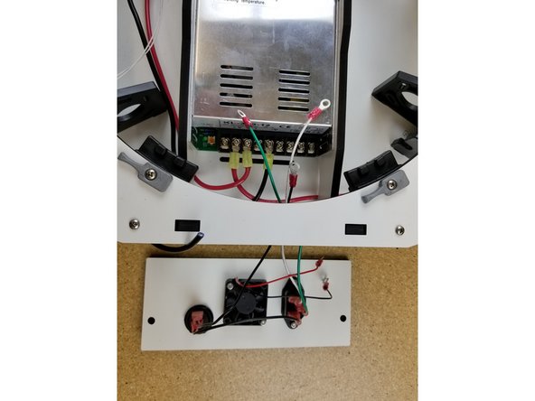
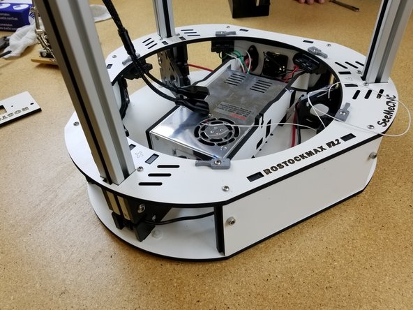
Feed the (5) wires from the power panel through the opening in the side of base assembly directly adjacent to the power supply.
-
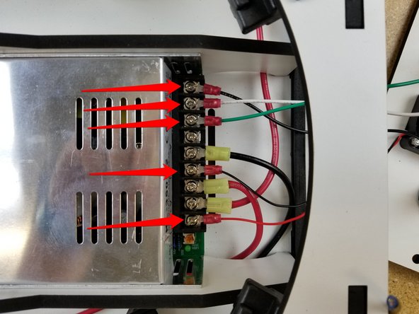
Remove the terminal screws from the power supply and install the wires. The colors correspond as before:
-
18awg black = L
-
18awg white = N
-
18awg green = ground
-
The red and black leads from the fan will connect to +V (red) & -V (black).
-
-
-
The power panel is secured to the injection molded side using (2) 10/32 x 5/8" screws as shown.
-
The injection molded side panel is NOT tapped. You will be tapping the hole with the screws as you secure the plate.
-
When aligning the plate, be sure to NOT pinch any wires between the plate and any other components.
-
-
-
We are done working on the power bay for now. Before moving forward ensure that all wires are 1) not being pinched and 2) not obstructing the movement of the fan blades.
-
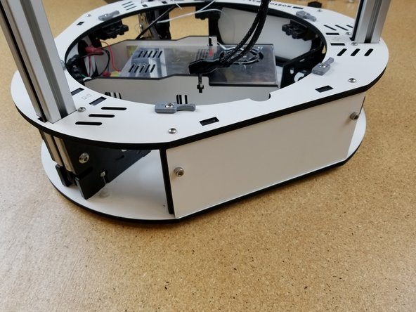
Install the remaining (2) laser cut side panels. These panel are both blanks and should NOT have any other cutouts on them.
-
-
-
Be sure to pass the bed wires through the black injection molded insulator BEFORE soldering the wires to the bed!
-
Follow this guide for preparing the Heated Bed
-
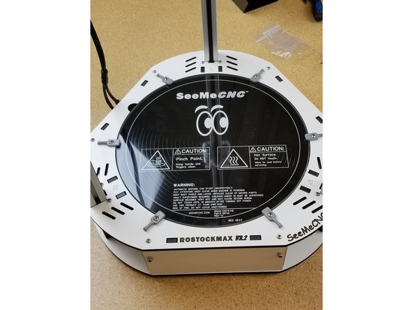
Install the bed as shown, and spin the bed clamps as shown to securely hold the glass in place.
-
-
-
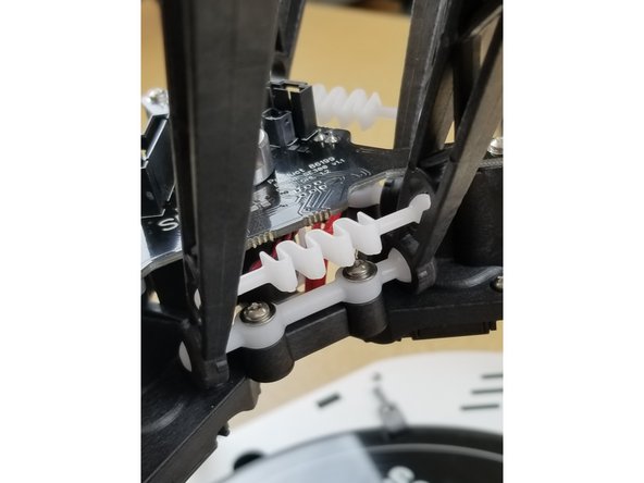
Install the ball cup arms and springs as seen here.
-
Be sure not to stretch the plastic springs out too much.
-
Do the same to attach the arms to the hotend assembly as well.
-
-
-
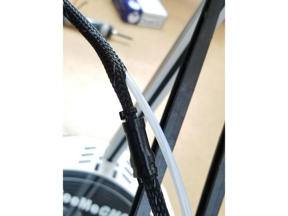
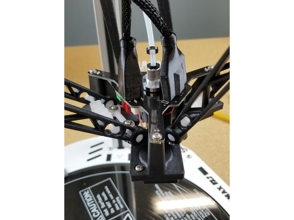
Insert PTFE here.
-
Exit the PTFE tube just before the y-splitter 3D printed part on the whip.
-
Plug in all three SE300 connectors and slide the 3D printed connector covers in place to give you hotend a nice, sleek, finished look.
-
-
-
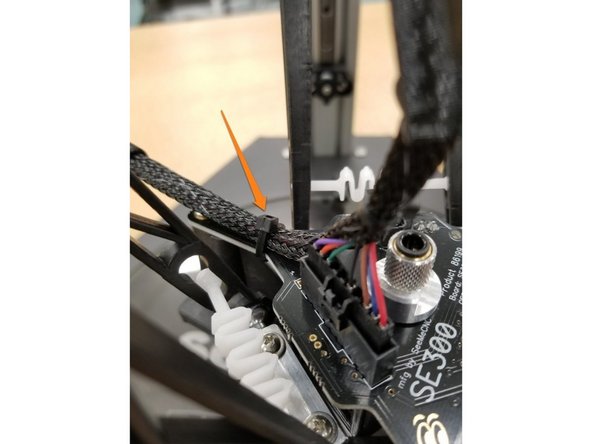
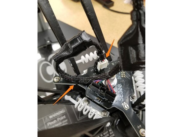
Attach a zip tie to the wires attaching the section of the whip after the 10 pin connector to the hotend board as shown in the photos.
-
Plug in the white 2 pin connector and black 4 pin connector.
-
Cover the plugs with the rubber boots.
-
-
-
Install the Duet cover panel as shown using the 1/2" #4 sheet metal screws
-
Install the side plate using the SHCS 10/32 cap screws.
-
-
-
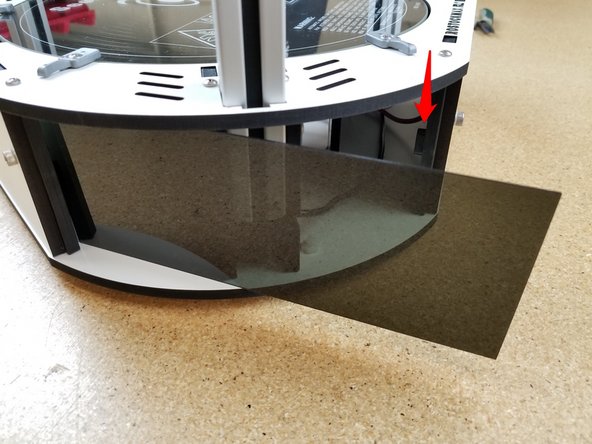
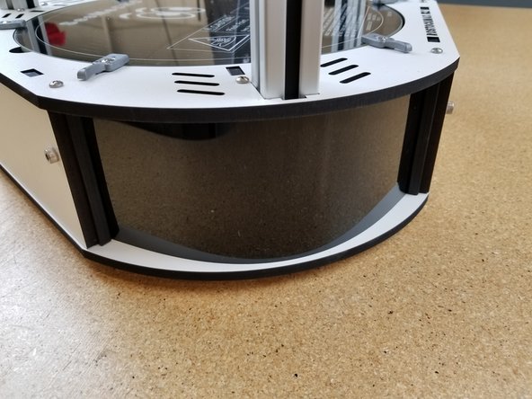
Remove the paper backing from both sides of the acrylic panels.
-
If you look at the injection molded base sides you will see the "stop" boss for the acrylic covers. Insert one side of the panel into the chosen corner, and then flex the panel into place.
-
Repeat for all the remaining corner covers.
-
Install the top hatch as shown.
-
-
-
Go Here next > SE300 Hotend Assembly guide
-
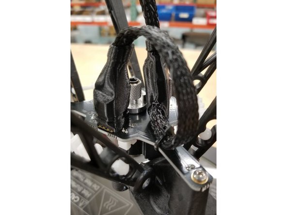
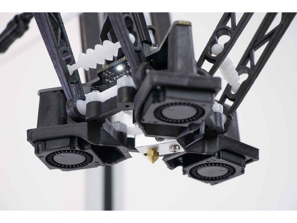
Install the SE300 hotend as shown in the picture. Snap on ball joints, install springs, and plug in bowden and whip connectors.
-
Plug in the power cable to printer. Turn the printer on. The hot end should light up, as well as the status LEDs on the Duet board.
-
We will now move on to the initial connection and setup.
-
Go Here Next > Configuring Rostock Max v3.2
-


Cancel: I did not complete this guide.
5 other people completed this guide.
5 Comments
I"m also asking the same question there are 3 pieces of the injection molded plastic, I assume these are for the travel arms somewhere. On a more serious note , a schematic showing the wiring for both for the AC supply and the 12VDC circuit for bed...I will be departing the build guide. to install a proper fused 3 pin AC connector used in the V4 edition. ALso am not a keen fan in replacing the duet board ,should it fry and will use a sSR to carry the load for the bed heater.. An index of the various steps with links to the departure point if this ”kit” had arrived from China, my comments would have been much more critical;. Good thing mine was the second last one , as far a s I know. Definitelly not for a Newbie
i
is.chowa@gmail.com - Resolved on Release Reply
What are the small black plastic injection molded components for? They have a slot on one side and an open crescent on the other.
Karalyn Tellio - Resolved on Release Reply
I agree with other comments about adding a list of tools and materials as well as the small font on the bags being VERY difficult to read. Parts bags were grouped by physical orientation (bottom plate, etc.), but assembly instructions jumped around enough that multiple bags were open at the same time. It would be more helpful is bags corresponded to instruction steps. Or maybe assign numbers to bags and then each step can note what bag(s) to pull hardware from. I also had a decent amount of hardware left over when done. So throughout the build I wasn’t sure if I had missed assembling something or if having extra was normal. I do appreciate having some extras. Lastly, my printer powered up and printed on its first try without me having to debug or fix any issues (other than trimming off extra belt on carriages). So that is a testament to the quality of the instructions.
Richard Casto - Resolved on Release Reply
I would suggest moving the motor mounting, and belt routing to be done BEFORE mounting the duet panels, duet, and side plates as this allows MUCH easier access to the screws for final tensioning of the belts. Unless using a stubby screw driver the side plates especially get in the way to access 2 of the 4 motor screws for final tightening.
The inventory list font i also would suggest increasing. This became the biggest issue since being such fine font size, i couldnt make a quick inventory and realize that one 84407 plate was missing before i started a 13 hour live stream build of the Rostock.. Didnt look good for SeeMeCNC to end up short a part on a $1000 kit. Even if just numbered the bags instead of individual parts lists in them, with a corresponding full page print out of what each numbered bag contains.
Matthew Weber - Resolved on Release Reply
I’d like to suggest adding a list of all tools and materials needed to complete the assembly at the beginning of the guide so that they can be gathered ahead of time.
I’d also like to suggest adding a list of all components/component bundles/bags that should be received with the kit so that an inventory can be done before assembly. Additionally, a printable or online viewable list of the contents of each bag (in a larger than 2 point font) would be helpful as well so that items can be accounted for.
Christopher Russell - Resolved on Release Reply