
-
-
Please thoroughly read the Introduction - Read Me First
-
Want to download this guide as a PDF? Click on the PDF link just above the image and save as PDF. Be aware that there are animations and youtube videos, critical to assembly, that do not translate to the PDF.
-
-
-
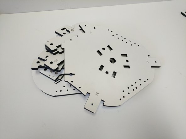
Your laser cut parts are cut and ready to go. They are taped in place in their panels to help protect them and ensure that you get all of the pieces.
-
A protective masking is applied to our sheets before we laser cut them. After removing your pieces from the sheets you will need to remove that protective mask from both sides of all pieces.
-
-
-
After you have removed the masking from your laser cut pieces you will be ready to start the build!
-
Lets first begin with preparing some of the sub-assemblies that will be used on this build. Click on the links below, each will open in a new window. When you have completed that sub-assembly, close the window and move on to the next sub-assembly.
-
If your machine is purchased before about February 2018, follow this hot end guide: HE280 Whip / Hotend Assembly
-
If you purchased your machine February 2018 forward, follow this hot end guide: 2018 HE280 Hotend Assembly
-
-
-
-
-
-
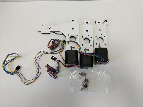
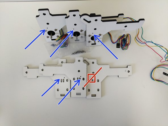
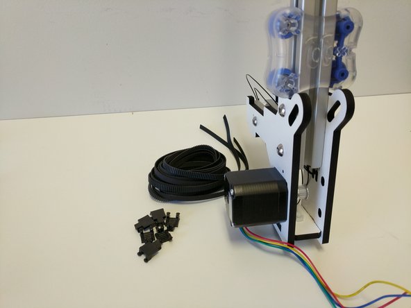
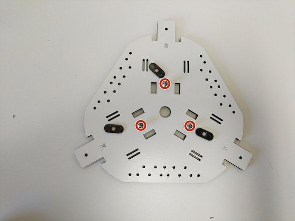
Locate the pieces shown in the image. You will have (3) laser cut parts labeled "Stepper Motor", (3) Stepper Motors, and a back of M3 x10mm machine screws & #4 Washers.
-
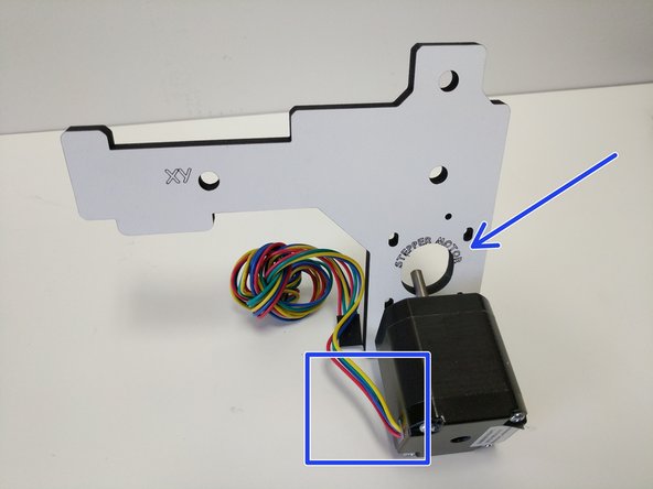
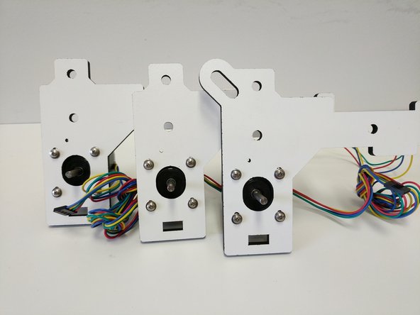
The stepper motors should be mounted so the body of the stepper motor covers the "Stepper Motor" text on the laser cut pieces.
-
Each stepper Motor is attached with the wires exiting towards the XY or Z tower labeling. using (4) M3 x 10mm machine screws and (4) #4 washers.
-
DO NOT TIGHTEN THE SCREWS, THE STEPPER MOTOR IS USED TO TENSION THE BELTS LATER.
-
-
-
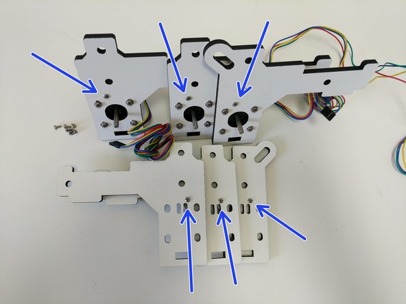
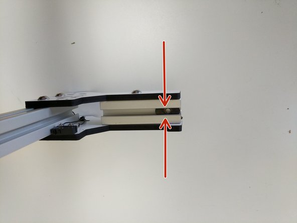
Locate the (12) #4 x 1/4" sheet metal screws and the remaining laser cut tower mount pieces
-
Note the proper location of the screws in the images. The screws should be driven from the side of the pieces that does not have engraved text.
-
-
-
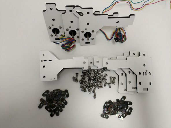
Locate the (50) 1/4-20 button-head machine screws and (50) TSLOT nuts.
-
Prepare each of the (12) plates with (3) of the button head screws and TSLOT nuts.
-
In this step and all other steps using the TSLOT nuts, the boss (ridge) on the nut should be facing away from the head of the button head screw.
-
The head of the button head screws should be on the side of the plates with laser engraving .
-
Get the button head screws engaged by 1 or 2 thread only, do not tighten.
-
-
-
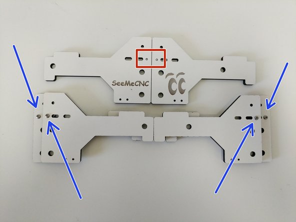
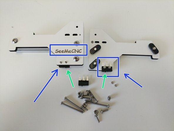
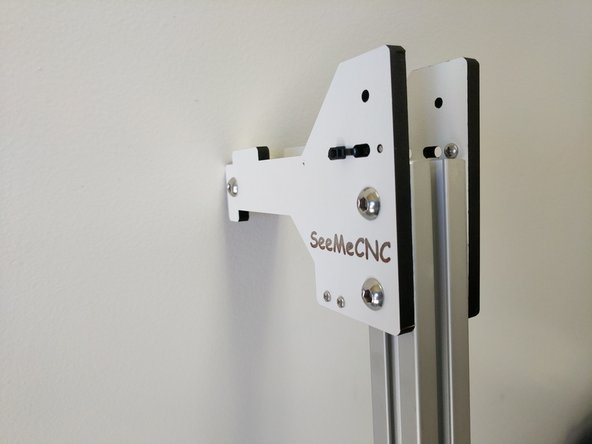
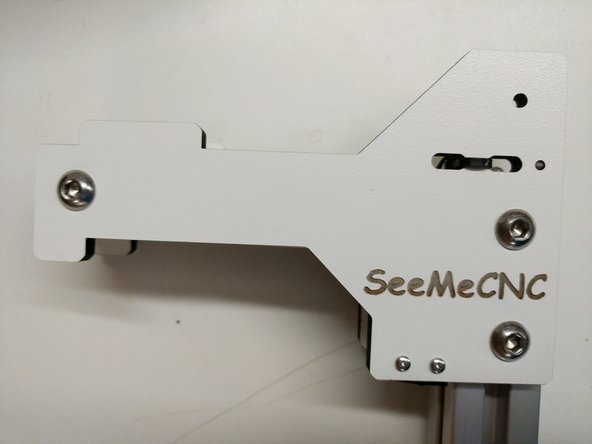
Locate the (6)2-56 x 5/8" & (6)2-56 nuts from the hardware pack and micro switches from the electronics hardware pack.
-
Remove the metal levers from the micro switches. This can be done by hand by gently twisting the lever out of place.
-
Attach the micro switches to the top tower mount pieces as shown. The micro switches will attach to the inside (side WITHOUT text) of the plates engraved "SeeMeCNC"
-
Note the orientation of the switches. The button should be closest to the TSLOT hardware (green arrows).
-
Fully tighten the screws/nuts.
-
-
-
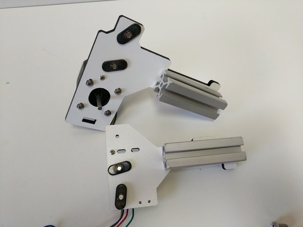
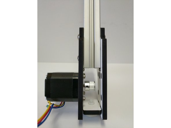
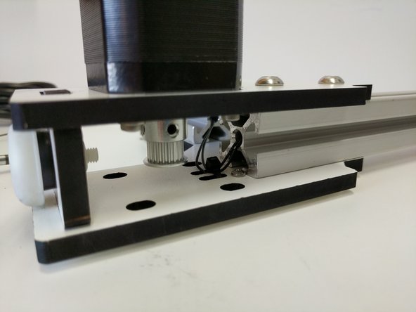
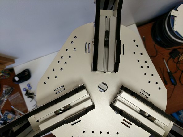
Locate the pack of (3)timing pulleys with set screws and the (6) 3.25" TSLOT Pieces.
-
Complete the following steps for each of the (3) base tower assemblies. Ensure that you match the (2) Z pieces and (4) XY Pieces)
-
Slide the TSLOT into one side of the plates as shown. You can loosely tighten the button head screw to keep it held in place. Do not tighten.
-
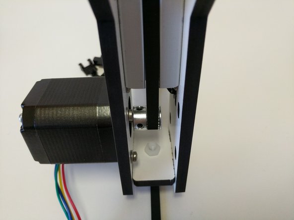
Install the timing pulley onto the stepper motor as shown in the image. (One of the set screws should be aligned with the flat on the stepper motor shaft). The face of the timing pulley should be flush with the end of the stepper motor shaft. Tighten both set screws fully.
-
Slide the opposite plate onto the TSLOT and loosely tighten the button head screw to keep it held in place. DO NOT TIGHTEN.
-
Perform the same operation noted above to attach the two sides of the top tower assembles.
-
-
-
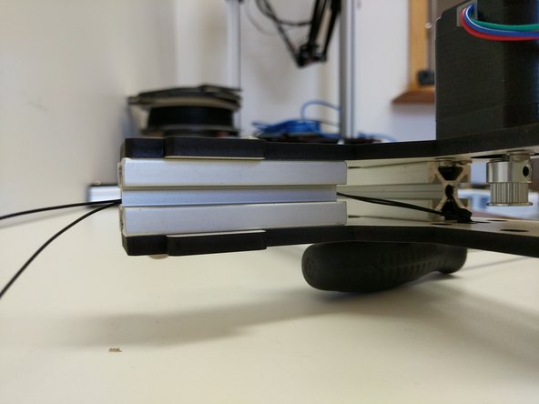
Locate the bag of foot hardware and (3) laser cut foot mount pieces.
-
Assemble each as shown. The nylon screw should go up through the black plastic leg, through the laser cut foot mount and finally secured with the nylon nut. After the screw/nut are tightened, press the foot onto the leg.
-
-
-
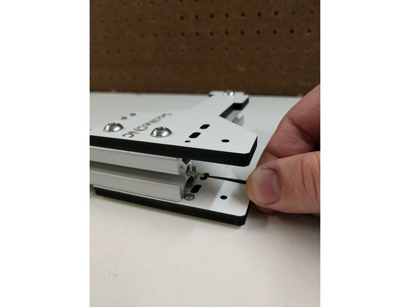
Spread the bottom of the plates for the base tower mount enough to insert the foot mounts. Ensure the foot is in the correct orientation (Shown in image)
-
Slide the 24" TSLOT into the base tower mount assembly until it reaches the stop screws. Hand tighten the button head screws. DO NOT FULLY TIGHTEN
-
-
-
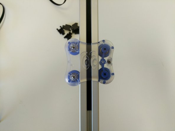
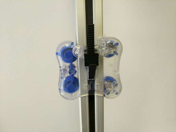
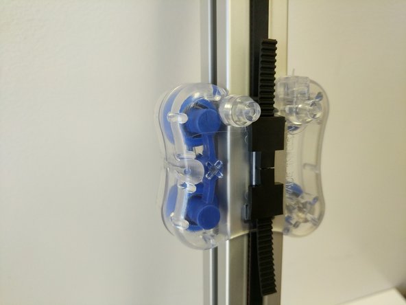
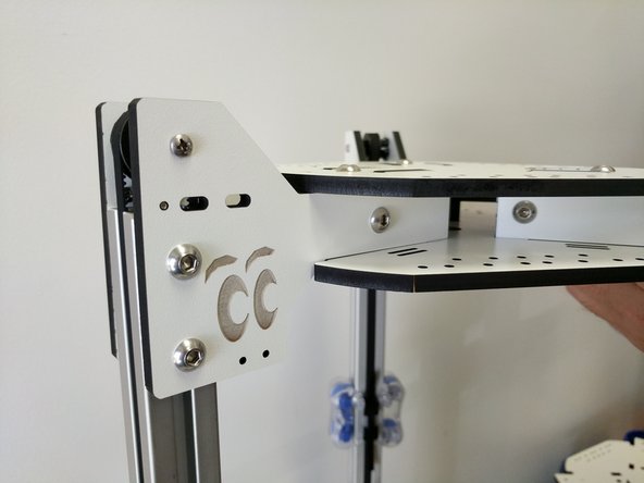
Slide the carriage that you previously assembled onto the TSLOT from the top. The Blinky Eye logo should be in the orientation shown in the image.
-
Repeat this process for the other (2) tower assemblies.
-
-
-
Slide the top tower mount assembly onto the 24" long piece of TSLOT until it reaches the stop screws. Loosely tighten the button head screws. DO NOT FULLY TIGHTEN.
-
-
-
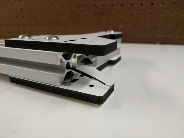
Locate the (6) 26awg black 1250mm long endstop wires
-
Run 2 wires through each of the towers center as shown. The ends of the wires without connectors should be in the top of the tower assembly.
-
If you have any difficulty getting the wires through the TSLOT, you can use a length of filament to help guide the wires through.
-
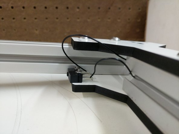
Route the wires to the end-stop and prepare them for soldering. You will be soldering the leads to the outer legs of the end-stop. The middle leg will be left without anything attached to it.
-
Some users find that it may be more helpful to remove the panel with the endstop attached to make soldering easier.
-
-
-
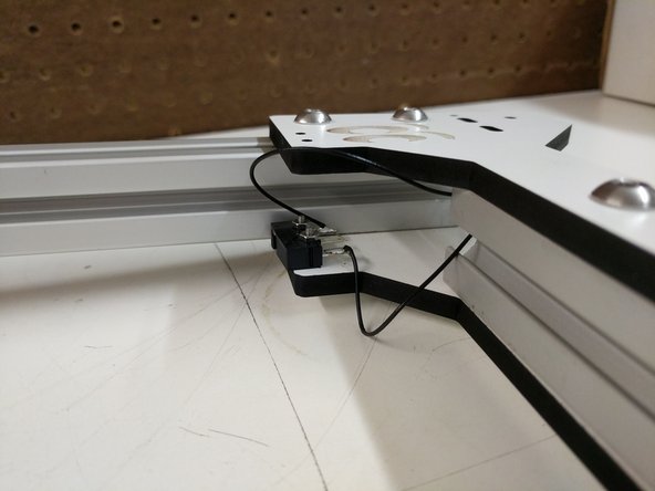
Solder the wires to the end-stop. Reminder: You should be soldering the wires to the outer legs of the end-stop.
-
Use one of the supplied zip-ties to secure the end-stop wires to the laser cut piece (same side as end-stop)
-
-
-
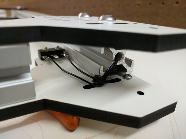
Secure the end-stop wire to the non-motor mount base laser cut piece using a zip-tie.
-
Route the wires as shown in the images.
-
Complete the work for the remaining (2) towers if you have not already.
-
-
-
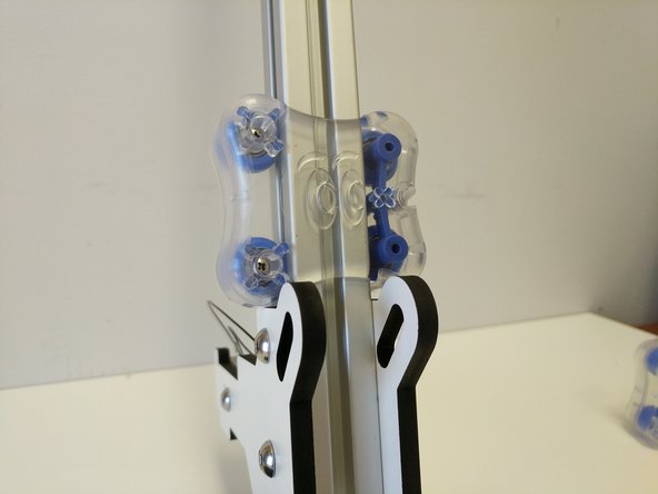
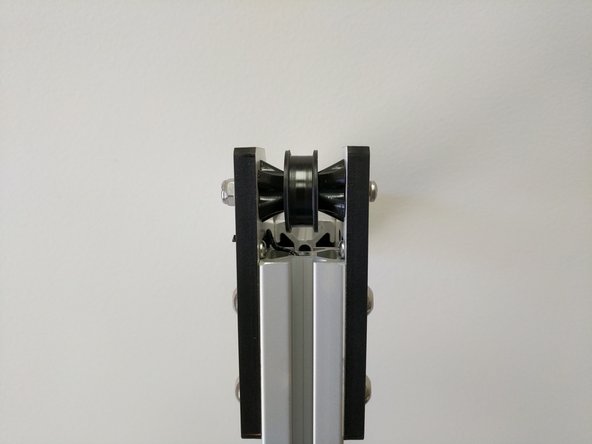
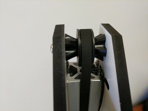
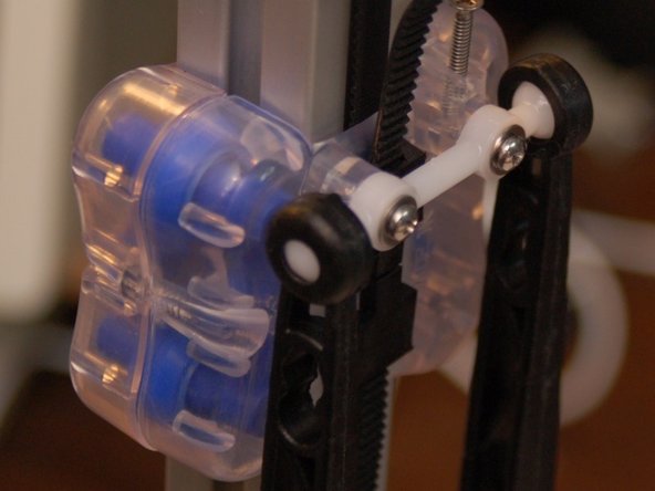
For this step you will need to locate the (3)R4 bearings (pre-pressed into the idler covers), (6) bearing standoffs, (3) 6-32x1.75" machine screws, and (3) nylon lock nuts.
-
Assemble the components as shown in the image. Do not fully tighten the 6-32 hardware at this time.
-
-
-
For the following steps you will need the (3) supplied timing belts, and (6) belt clamps that came in the carriage pack hardware.
-
At this time, be sure the the (4)screws attaching the motor to the laser cut piece are not tight. The motor should be able to slide up and down in the slots.
-
-
-
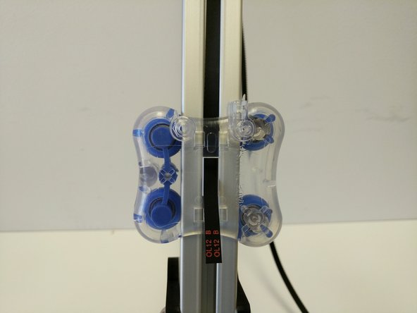
Start by feeding the belt between the carriage and TSLOT (at the top of the carriage) and through the rectangular opening in the center of the carriage.
-
There are different techniques for pulling the belt through the opening such as using tweezers, and exacto knife, or a zip-tie (as a ramp).
-
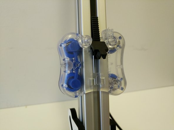
Lift up on the belt (less than 1" above the top of the carriage) and insert the belt clips legs into the two upper rectangular cutouts.
-
Finish by pressing the bottom of the belt clip into the carriage until it snaps into place securing the belt.
-
-
-
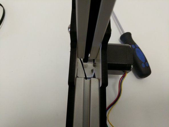
Route the belt up the TSLOT and over the idler bearing.
-
Route the belt down the opposite side of the tower. When you get to the carriage, you will need to route the belt inside the carriage between the carriage body and the TSLOT.
-
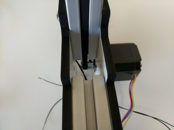
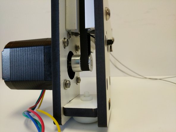
When you get to the bottom of the tower assembly route the belt around the timing pulley.
-
-
-
Begin routing the belt up the TSLOT.
-
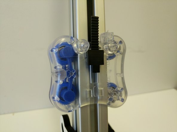
Feed the belt up and between the carriage and TSLOT (at the bottom of the carriage) and through the rectangular opening in the center of the carriage.
-
Hold the carriage stationary and pull down on the belt with a decent amount of force, while doing so insert the belt clips legs into the two lower rectangular cutouts. (an extra set of hands for this step may be helpful).
-
Finish by pressing the top of the belt clip into the carriage until it snaps into place securing the belt.
-
-
-
Ensure that the end-stop wires are clear of the belt path at the top & bottom of the assembly.
-
Use the body of the stepper motor to press down tensioning the belt.
-
Note that you don't want the belts to be so tight you can pluck them like a guitar string. The more you tighten the belt, the harder the motor has to work in order to move the carriage.
-
When you are happy with the amount of tension that you have on the belt, tighten the (4) M3x10 machine screws.
-
-
-
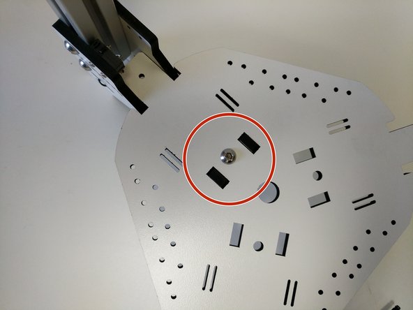
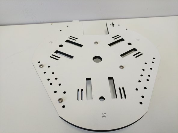
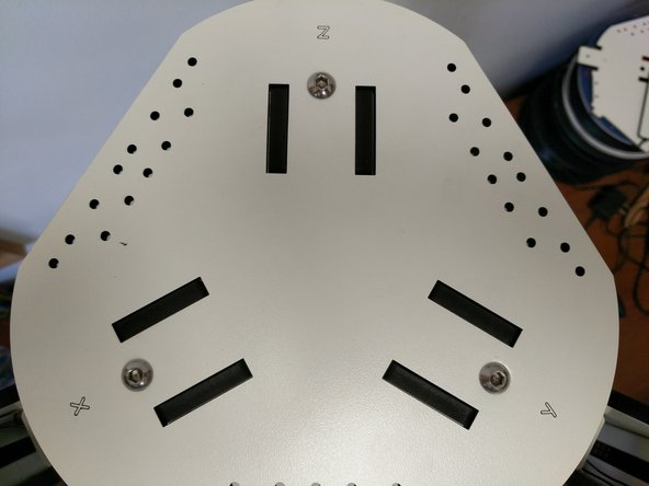
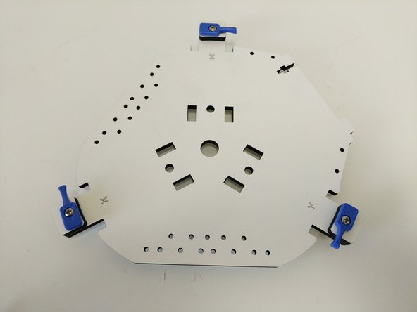
Locate the top assembly base plate (shown in image), (3) 1/4-20 button head screws, and (3) TSLOT nuts.
-
In this step and all other steps using the TSLOT nuts, the boss (ridge) on the nut should be facing away from the head of the button head screw.
-
All of the horizontal plates are laser engraved with XYZ tower indicators. You are going to be installing all of these main horizontal plates in the orientation that puts the XYZ text face up.
-
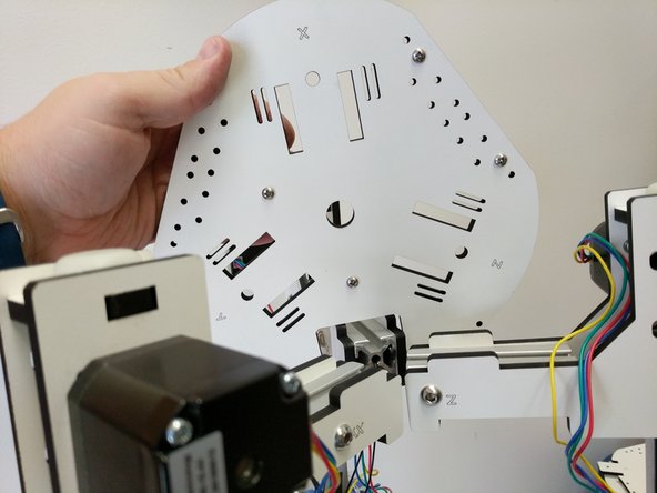
You will install the Z tower assembly first. To do so, flip is upside down and slide a TSLOT nut into the TSLOT as shown. Align the nut as shown.
-
Next install the top assembly base plate (ensure you get the Z tower position with the Z tower) by aligning the tabs and cutouts. Hold the panel down flush against the tower plates. Look through the hole for the 1/4-20 button head and ensure that the TSLOT nut is centered with the hole. If it is not use your hex driver to move it into position.
-
If you are having troubles getting the button head screws to engage the TSLOT nuts, first ensure that you have the nut aligned with the hole, second loosen the 1/4-20 button head screws slightly on the side plates.
-
Insert and tighten the 1/4-20 button head screw. You CAN fully tighten this screw.
-
-
-
Perform the procedure from the previous step for the remaining (2) towers.
-
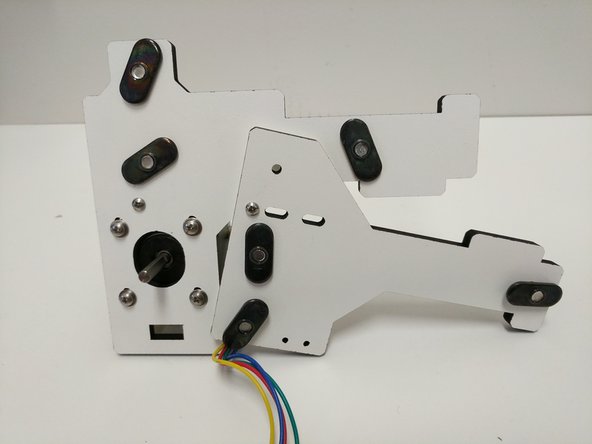
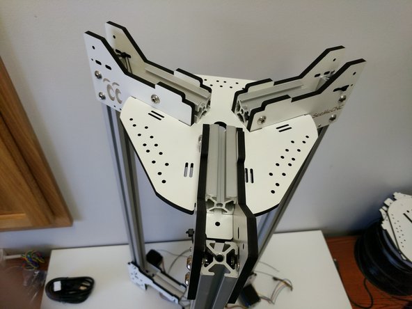
When you have completed your assembly it should look like the images.
-
Leave the printer upside down for the next steps.
-
-
-
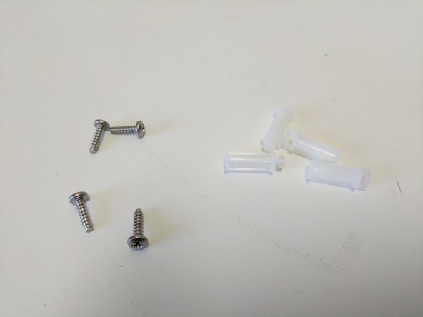
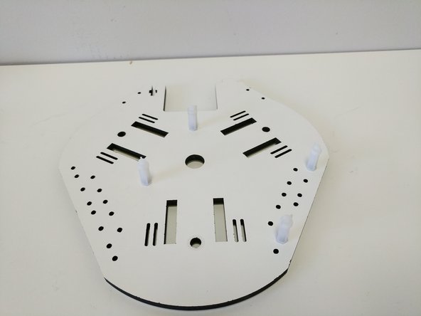
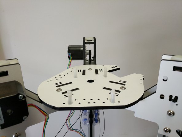
Locate the base assembly base plate (shown in image), (4) #6 x 1/2" sheet metal screws, (4) board supports.
-
Attach the board supports in the locations shown. Tighten these at this time.
-
The board supports should NOT be on the side of the base assembly base plate with the XYZ indicators.
-
-
-
Locate (3) 1/4-20 button head screws, and (3) TSLOT nuts. You will use those to fasten the plate that you just attached the board mounts to.
-
In this step and all other steps using the TSLOT nuts, the boss (ridge) on the nut should be facing away from the head of the button head screw.
-
All of the horizontal plates are laser engraved with XYZ tower indicators. You are going to be installing all of these main horizontal plates in the orientation that puts the XYZ text face up.
-
Slide the (3) TSLOT nuts into the TSLOT in the approximate location of the 1/4-20 button head screw holes.
-
Install the base assembly base plate. Ensure that you get the tower orientation correct. Tighten the 1/4-20 button head screws fully.
-
If you are having troubles getting the button head screws to engage the TSLOT nuts, first ensure that you have the nut aligned with the hole, second loosen the 1/4-20 button head screws slightly on the side plates.
-
-
-
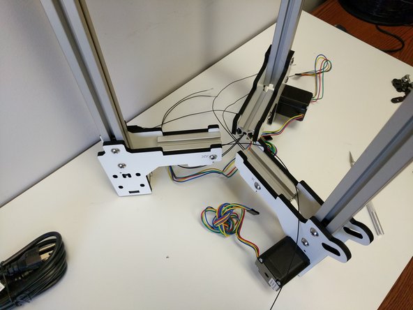
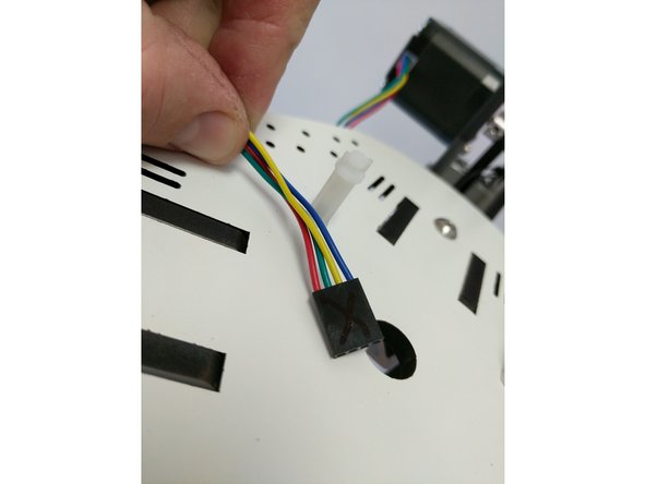
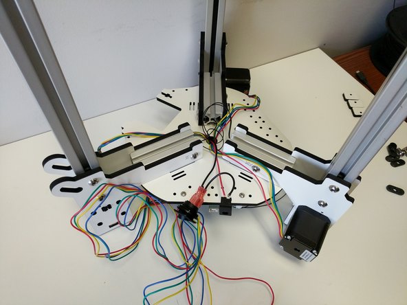
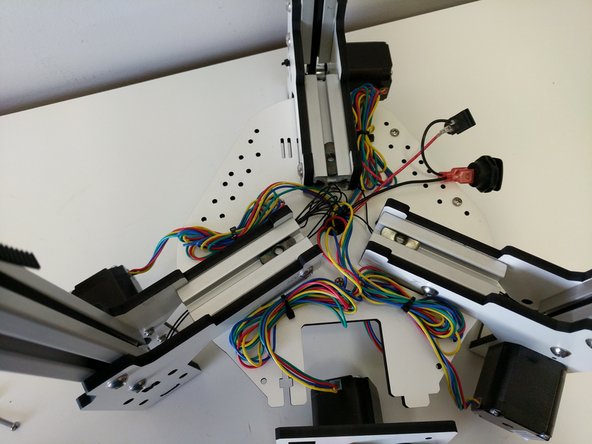
Label each of the stepper motor wires X Y Z with a permanent marker.
-
Route the wires through the hole in the center of the base assembly bottom plate. The machine is still upside down at this point and the wires should be coming up through that hole.
-
-
-
Group the wires as shown.
-
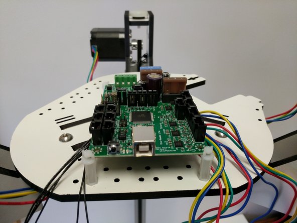
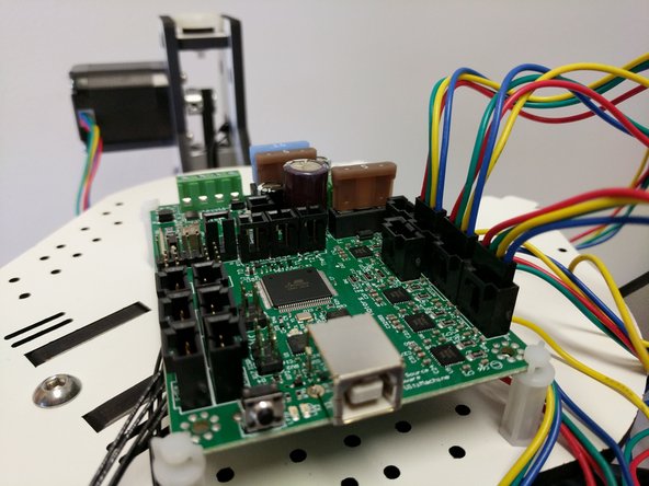
Install the Mini-RAMBo in the board supports. The board supports may need to be rotated so that they are at 45 degree angles to the board. They will catch on the 4 corners of the board.
-
Insert the stepper motor plugs into the Mini-RAMBo. Be sure to put the correct stepper motor in the correct port. and the red wires is on the side of the port closest to the fuses.
-
From the end of the Mini-RAMBo with the USB port the stepper motor ports are: XYZE
-
-
-
In the next step you will be installing end-stop connectors on your end-stop wires. The wire are pre-terminated for this connector.
-
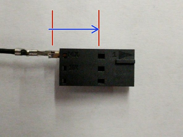
In the first image you will see the connector with a red arrow pointing to arrow on that connector. That is pin 1.
-
In the second image is the proper orientation for inserting the wire in the connector. When you insert the wire you will push it into the connector until you hear/feel the connector click into place. Give the wire a gentle pull back out to ensure that it is secure.
-
-
-
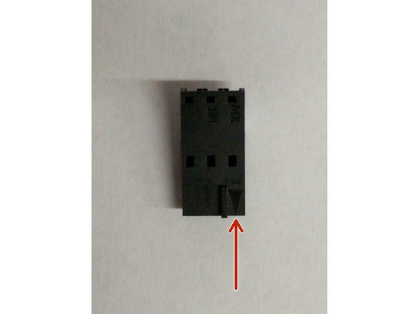
Locate the (3) 3 pin connector housing positive latch (shown in the first image).
-
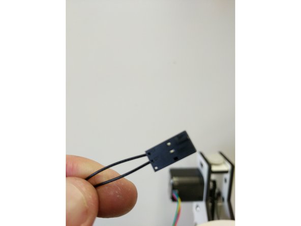
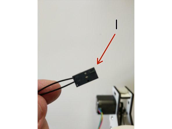
Identify the endstop wires in 3 pairs of two. X Y & Z. You can identify the pairs by gently pulling them from each of the towers one at a time.
-
Insert the wires into the 3 pin connector housing into pin 1 (with arrow) and pin 2 until you hear/feel a click. Do this for the X Y & Z tower endstops.
-
Plug the endstops into the Mini-RAMBo in the correct X MAX Y MAX & Z MAX locations.
-
-
-
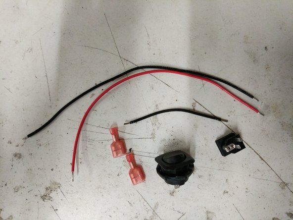
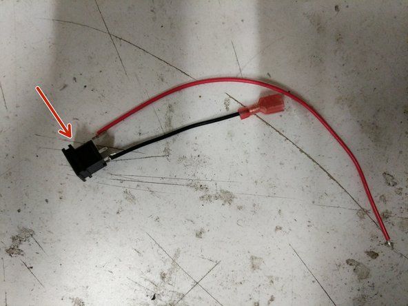
Locate the following parts from your electronics pack.
-
Remove the insulation from the ends of the 18awg black wires.
-
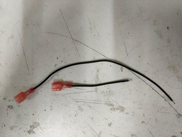
Crimp the spade connectors onto the ends of these 18awg black wires as shown.
-
-
-
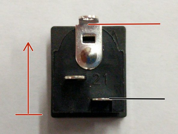
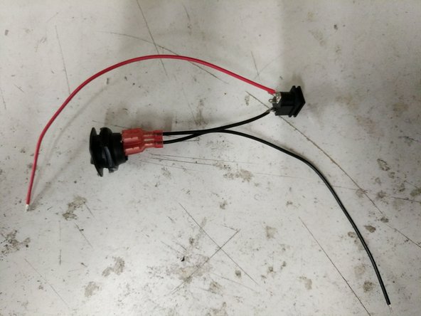
Solder the 18awg red wire to the top of the barrel power jack connector. (top is indicated by the red arrow)
-
Solder the 18awg short black wire (with spade conector attached) to the bottom of the power jack connector.
-
Connect the spade terminals to the rocker switch.
-
-
-
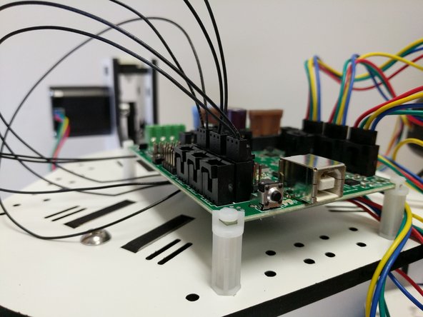
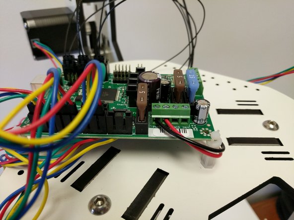
Route the red and black 18awg power wires through the base plate. The wires will come up under the Mini-RAMBo board.
-
Bring the wires around the board support and secure them in the -PWR IN- terminals (-/+) Tighten the terminals.
-
-
-
Flip the printer over so that it is right side up.
-
Insert (3) TSLOT nuts into the TSLOT in the top of the printer. Try to align them as shown in the image (to prevent having to move them around too much after the top plate is installed.
-
In this step and all other steps using the TSLOT nuts, the boss (ridge) on the nut should be facing away from the head of the button head screw.
-
All of the horizontal plates are laser engraved with XYZ tower indicators. You are going to be installing all of these main horizontal plates in the orientation that puts the XYZ text face up.
-
Install the top assembly top plate. Don't be too rough or those TSLOT nuts will move.
-
Fasten the top assembly top plate with (3) 1/4-20 button head screws.
-
If you are having troubles getting the button head screws to engage the TSLOT nuts, first ensure that you have the nut aligned with the hole, second loosen the 1/4-20 button head screws slightly on the side plates.
-
-
-
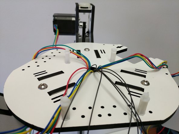
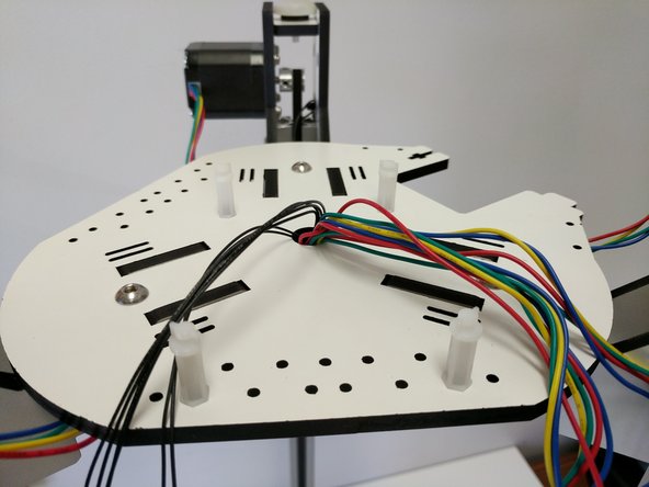
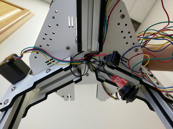
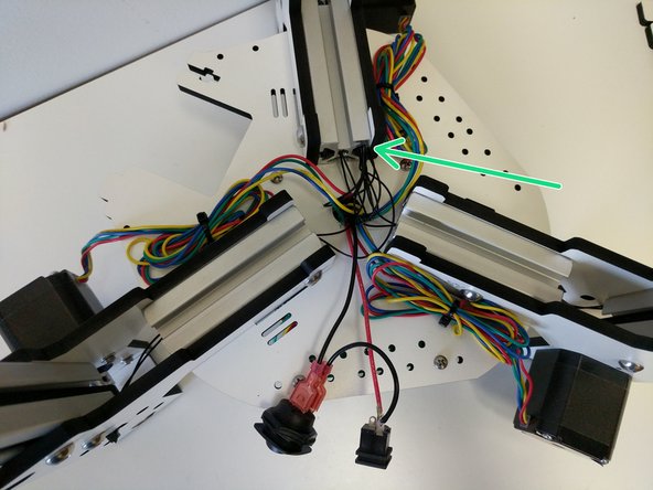
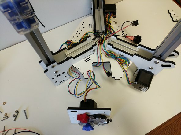
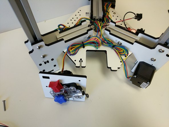
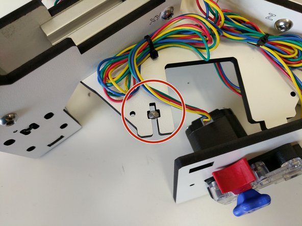
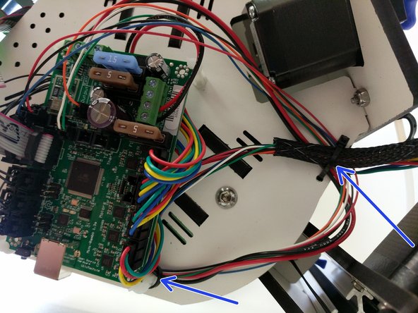
Before we can install the base assembly top plate, we need to tame the wires in the base.
-
Pull the excess stepper motor wires up through the hole in the base of the printer. Be sure not to pull so hard to put strain on or damage the wires or Mini-RAMBo connectors.
-
Bundle the wires together based on which stepper motor they go to and secure to the base assembly bottom plate using the supplied zip-ties and the cable management slots.
-
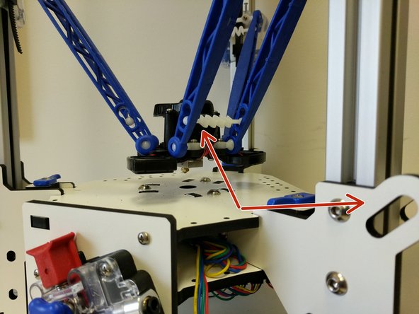
For taming the end-stop wires, you pull the excess wires up and insert them into the side of one of the short TSLOT pieces. (I have indicated this with a green arrow).
-
-
-
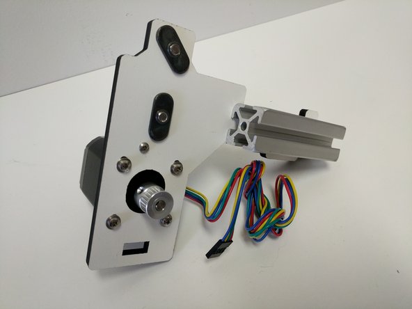
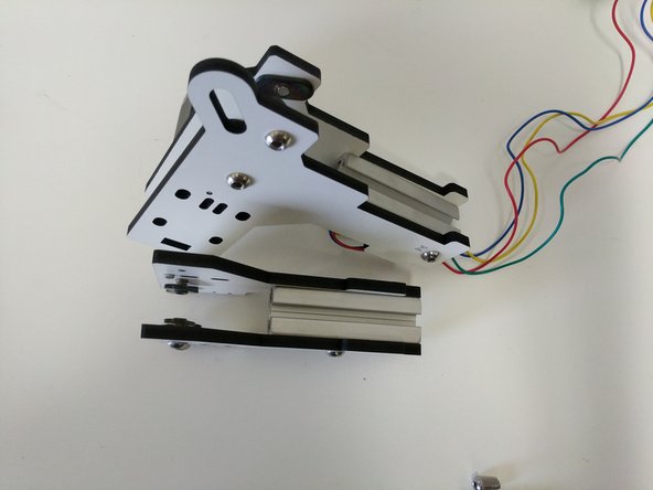
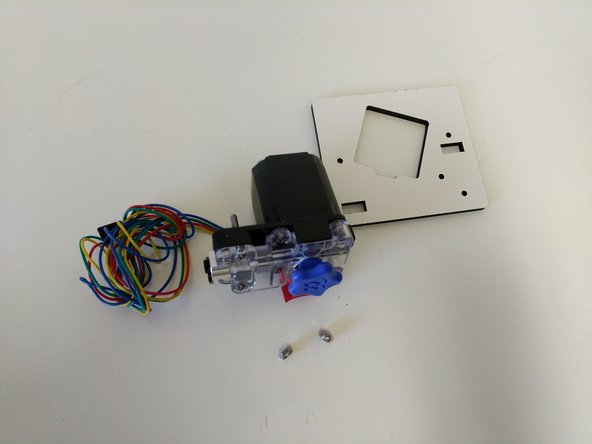
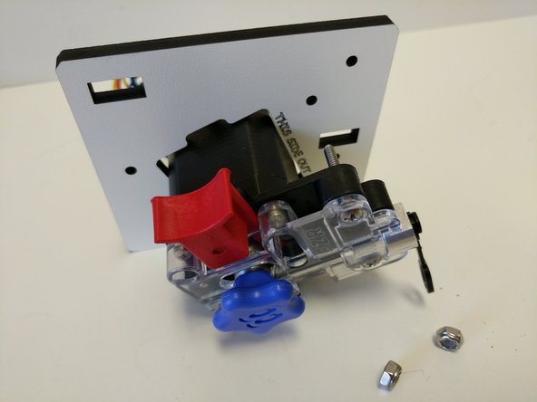
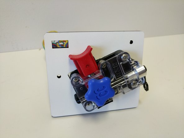
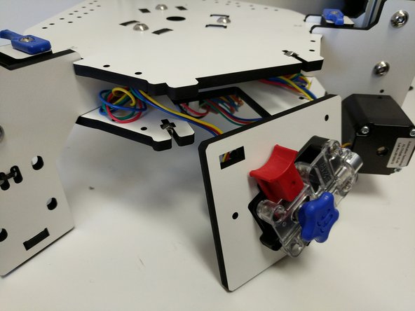
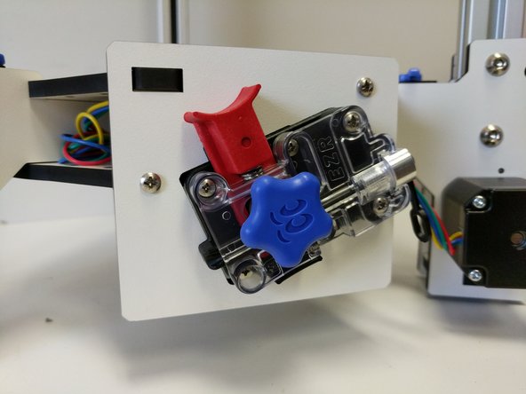
Mount the EZRStruder to the EZR Struder plate as shown in the images. (The 6-32 x 1" screws were put in the EZR Struder's mounting holes for safe keeping when you built it)
-
The EZR Struder should cover the text "THIS SIDE OUT" so you know that you have the correct orientation.
-
Tighten the 6-32 hardware fully.
-
-
-
Set the EZR Struder on the work surface with the printer. Route the stepper motor wire down through the hole in the center of the base assembly base plate and plug it into the Mini-RAMBo. Plug into the connecter closest to the fuses. Make sure the red wire on the connecter is positioned closest to the fuse.
-
Pull the slack back out of the wire, bundle it and zip-tie if to the base assembly base plate (as shown).
-
-
-
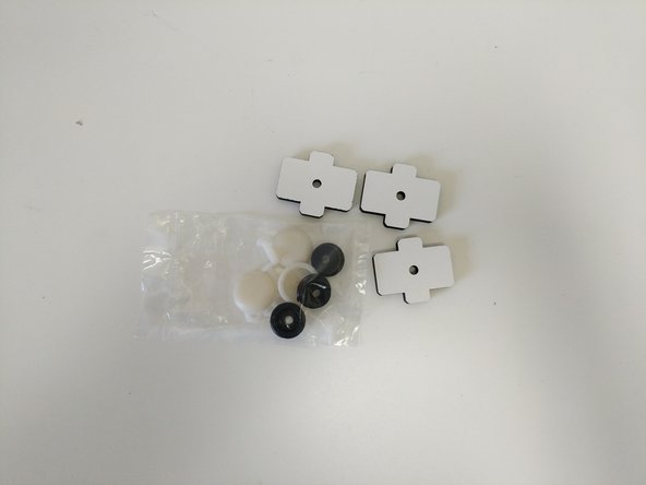
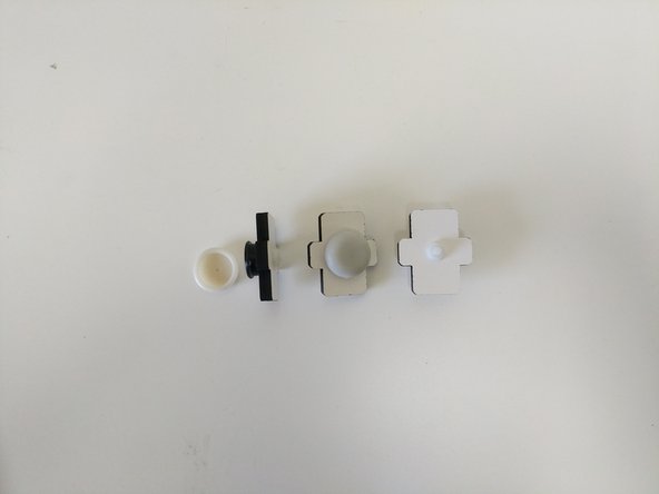
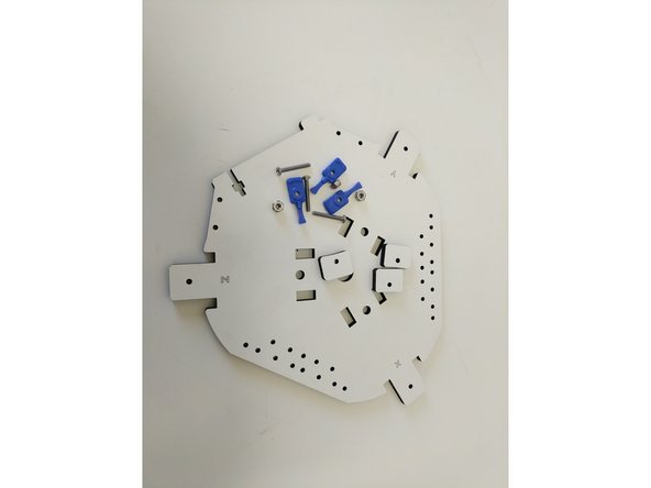
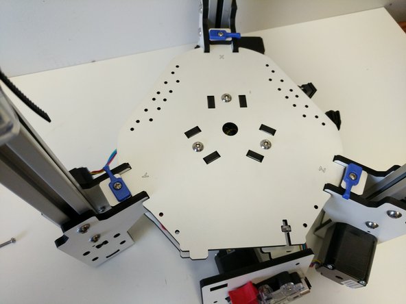
Locate the (3) 6-32 x 1" screws, (3) 6-32 nylon lock nuts, (3) blue build plate clamps, & (3) laser cut build plate spacers.
-
Prepare the pieces as shown.
-
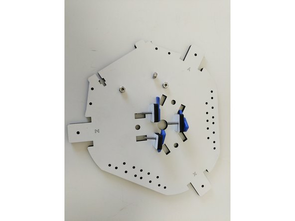
Install the pieces as shown.
-
You do NOT need to fully tighten these pieces.
-
-
-
Insert (2) nylon lock nuts into the "t" shaped cuts in base assembly top and bottom plates. The flats of the "t" shaped cuts will be against the flats on the nuts. Match the orientation for the nut (for the nylon insert) with that in the image.
-
Install (3)TSLOT nuts into the TSLOT. Align them as shown in the image.
-
In this step and all other steps using the TSLOT nuts, the boss (ridge) on the nut should be facing away from the head of the button head screw.
-
All of the horizontal plates are laser engraved with XYZ tower indicators. You are going to be installing all of these main horizontal plates in the orientation that puts the XYZ text face up.
-
Ensure that there are not any wires that will be pinched when installing the base assembly top plate.
-
Install the base assembly top plate. Fasten with (3) 1/4-20 button head screws. You can fully tighten these screws.
-
If you are having troubles getting the button head screws to engage the TSLOT nuts, first ensure that you have the nut aligned with the hole, second loosen the 1/4-20 button head screws slightly on the side plates.
-
Full tighten ALL of the 1/4-20 button head screws in all locations at this time.
-
-
-
Install the EZR Struder using the (2) 6-32 X 1" machine screws. You can fully tighten these.
-
-
-
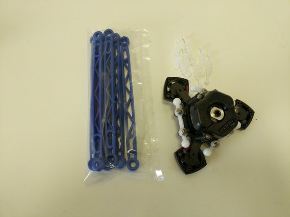
Locate the remaining ball joints and hardware from the arm pack.
-
Align the ball joint with the posts on the inside of the carriage and press on. You should attempt to evenly press the ball joint onto the carriage.
-
Secure the ball joint to each post using a #4 washer and a #4 x 1/2" sheet metal screw.
-
Repeat these steps for each of the three carriages.
-
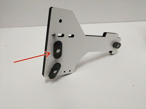
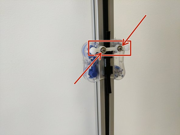
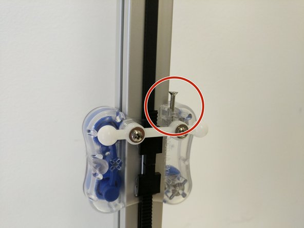
Install the 4-40 x 3/4" screws into the top of the carriage as shown in the image. You should tighten the screw until you start to feel some resistance. At that point STOP and do not tighten any further.
-
This screw is the trigger for the end-stop. You can move the carriage up and ensure that is presses the button on the end-stop.
-
-
-
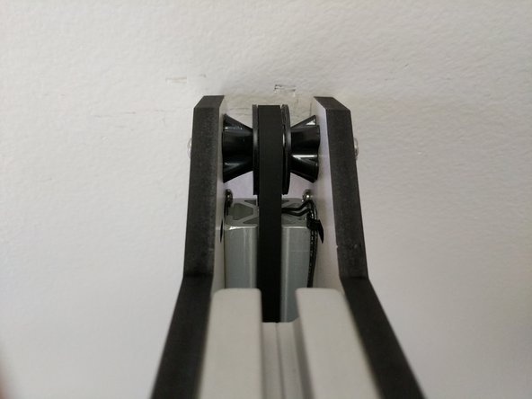
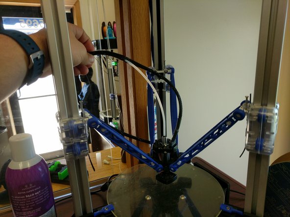
Locate the (6) Orion Arms (blue) and the (6) arm tension springs. *** You must start with the blue Orion Delta arms even if you intend to print using the black Rostock Max Arms ***
-
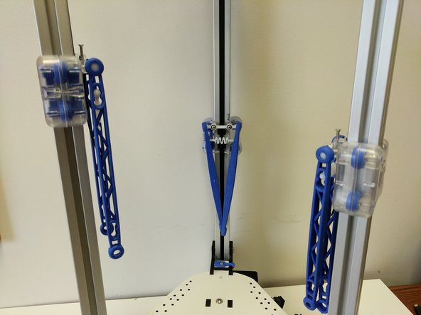
Begin by inserting 1 tension spring between 2 arms. Install those two arms onto the ball joints. You should feel a gentle snap, that is the indication that the arms are fully seated. Repeat for the other 2 sets of arms.
-
Identify the Z Tower. Insert a tension spring between the two arms at the end where the hotend will be installed. Install that set of arms on the hot end in line with the fan that is vertical (indicated with red arrows)
-
Complete the install for the remaining 2 sets of arms.
-
-
-
The Whip wires are prepared for the RAMBo board, but the H2 is equipped with the Mini-RAMBo. We will have to modify 4 wires to compensate.
-
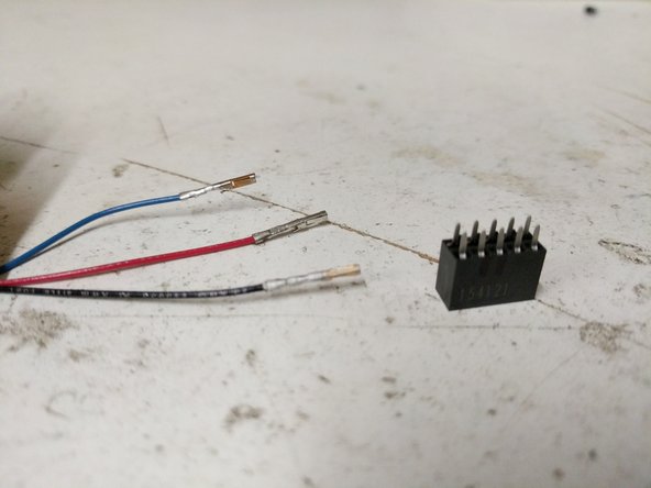
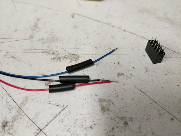
The first step is to locate the 10 Position 2X5 Connector. Then isolate the 26awg red, black, and blue wires from the whip. The ends of those wires will have connectors pre-installed. You will need to cut the connectors off of the wires.
-
Strip approximately 3mm of insulation off of each of the wires.
-
Slide some heat shrink tubing down over each of the 3 wires.
-
-
-
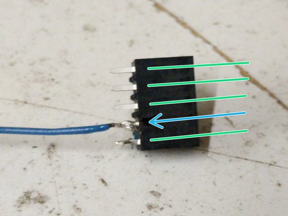
You will now be soldering the 3 wires to the 10 position connector. Begin with the 26awg blue wire. Note the location in the image.
-
Flip the connector over 180 degrees
-
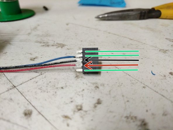
Solder the 26awg red and black wires to the 10 position connector in the positions indicated in the image.
-
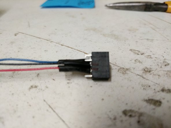
Slide the heat shrink tubing down over the soldered connections and heat it.
-
-
-
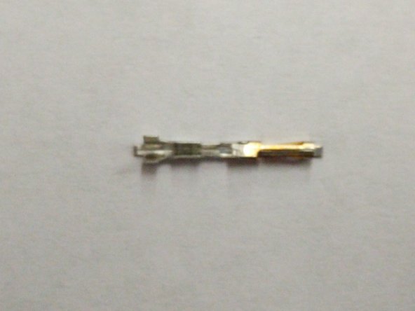
For connecting the whips fan lead to the Mini-RAMBo, you must add a connector the orange wire. There are two of these connectors in your kit in case you have problems on the first on.
-
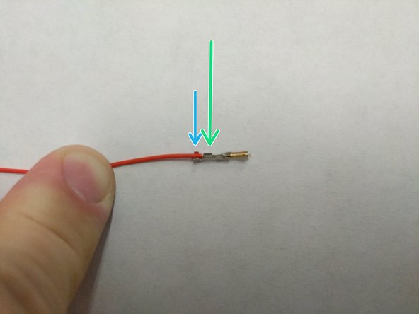
Strip the insulation off the end of the orange wire approximately 5mm.
-
Insert the wire into the connector as shown. The wire should be inserted such that the insulation will be captured by the crimp as indicated with a blue arrow and the stranded wire will be capture as indicated with a green arrow.
-
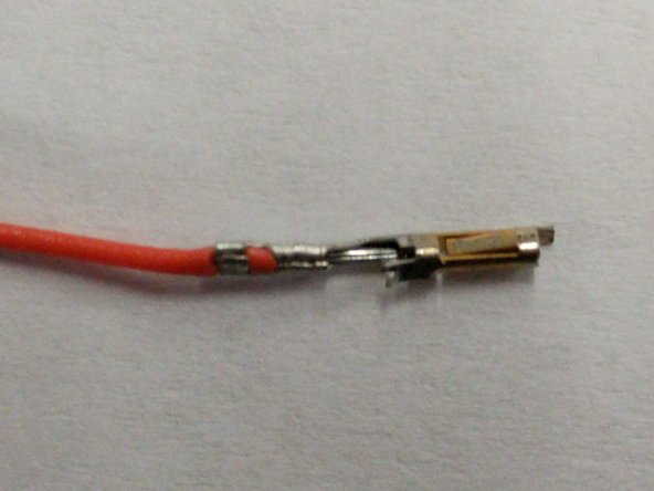
Use a pair of needle nose pliers to fold the crimp tabs over on the wire / insulation one tab at a time.
-
The completed crimp should look like the third image.
-
-
-
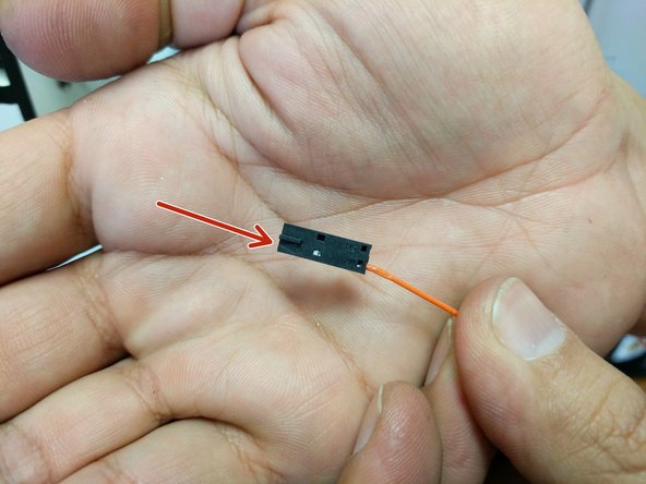
Insert the prepared wire and connector in the 2 pin latching connector in pin 1 (indicated with an arrow until you hear / feel a click. (just like with the end-stop wires)
-
-
-
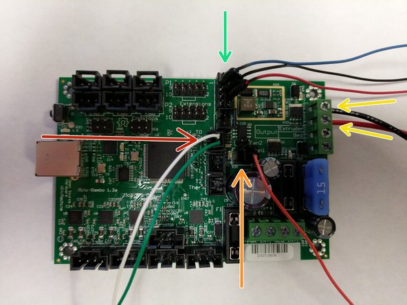
NOTE: This Mini-RAMBo has been removed from the machine for the purposes of this step. Also all other connections have been removed for clarity to illustrate the whip connections.
-
The green arrow indicates the 10 position connector. The red and black wires should be installed closest to the fuses.
-
The orange arrow indicates the orange layer fan wire in the 2 pin connector. That connector is keyed so there is only one proper way to plug it in.
-
The yellow wires indicate the + (red)/- (black) power wires for the whip.
-
The red arrow indicates the green and white thermistor wires in the 2 pin connector. That connector is keyed so there is only one proper way to plug it in.
-
-
-
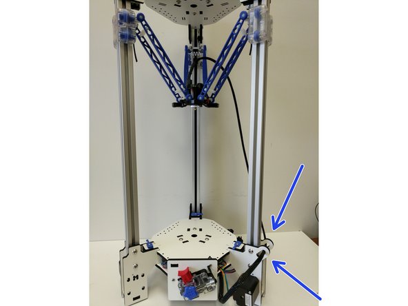
Route the end of the whip (with 8 position pluggable connector) through the retaining loops on the back of the Z axis tower. Plug the whip into the HE280 Hotend.
-
Secure the whip to the bottom base plate using a zip tie in the location specified in the image. Also secure the whip to the edge support standoff as indicated.
-
Properly secured wires will prevent any low hanging wires.
-
-
-
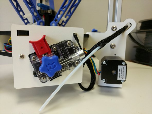
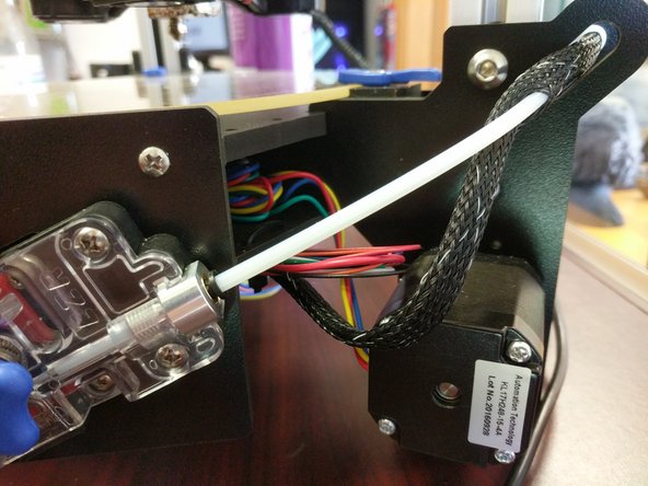
The Bowden tube is carried inside the mesh loom that holds the hot end wiring.
-
The PTFE will enter the mesh loom approximately 90mm beyond the extruder. Open a gap in the mesh by pressing two areas about 1" apart toward each other. This will expand the loom.
-
Insert the Bowden tube into this opening and thread it through the loom until it reaches a point about 225mm from the end of the hot end connector.
-
Open the loom as you did previously and thread the Bowden tube through the exit provided.
-
-
-
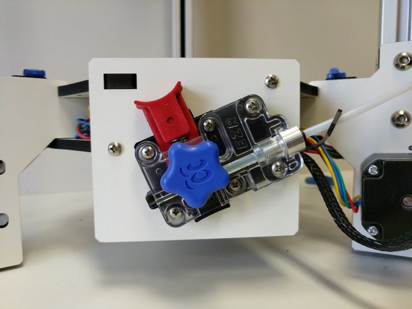
Slide a lanyard clip onto the Bowden Tube.
-
Slide the Bowden Tube into the end of the EZR Struder until it is fully seated.
-
Lift the black ring on the PTC adapter and insert the lanyard clip in to prevent the Bowden Tube from being able to "walk out"
-
Give the Bowden Tube one final push into the EZR Struder to ensure that it is fully seated.
-
-
-
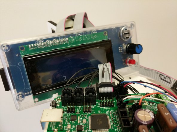
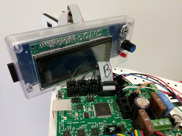
Label the ribbon cables A/B on each end.
-
Install the A ribbon cable on the Mini-RAMBo on the 2x5 pin header closest to the edge of the Mini-RAMBo. The red stripe should be closest to the fuses.
-
Install the B ribbon cable on the Mini-RAMBo on the 2x5 pin in front of where you just installed the A ribbon cable. The red stripe should be closest to the fuses.
-
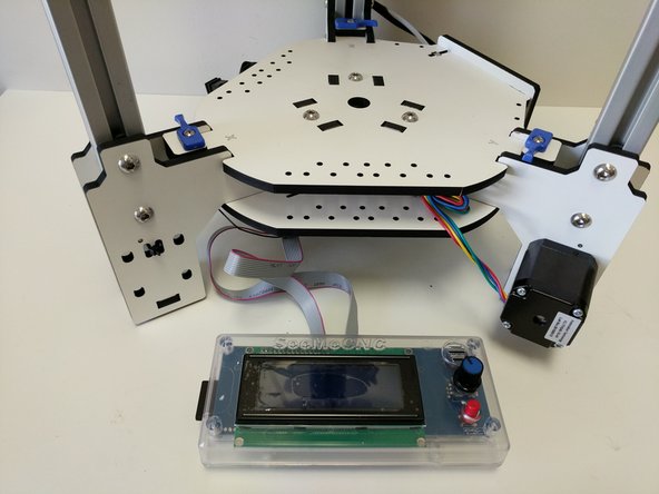
For now, until you print the LCD mount, you will lay the LCD controller in front of the printer.
-
-
-
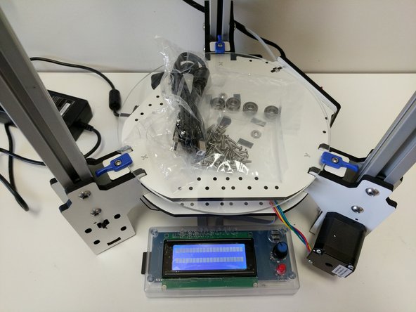
All of the extra vitamins are yours! We provided (4) extra R4 bearings to use for a spool holder, (6) Rostock Max length ball cup arms, and plenty of #4 x 1/2" sheet metal screws to install custom accessories.
-
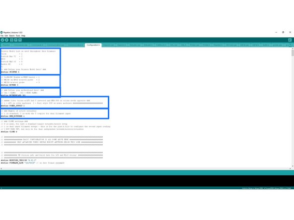
As of the time of release for the H2 the custom pieces are: LCD Mount, Power Input Block, Name Badge. These files can be accessed and downloaded from: Github
-
-
-
Next you will need to install firmware on the RAMBo board and then calibrate the printer. Don't worry, with the HE280 calibration is simple.
-
-
-
-
When you decide that you would like to switch between the different arms there is a simple GCODE file to fun to update the firmware with the new arm length and other critical firmware details.
-
-
After you have switched the arms you will need to run the correct GCODE (download link above). You can run the GCODE by:
-
Saving it to the SD card and running it like a normal print.
-
Adding it to the print que in MatterControl and running it like a normal print.
-
You are now ready to run the printer calibration as instructed here: Calibrating Your Printer
-


Cancel: I did not complete this guide.
6 other people completed this guide.
Attached Documents

3 Comments
For completeness, there needs to be added a step that mentions placing the glass bed on the printer.
Tim Koeller - Resolved on Release Reply
Step 47 and 48 show the Bowden tube at the EZStruder end. Nowhere did I find any reference to installing the tube in the wiring whip mesh or attaching the tube to the HE280. Did I miss the instructions somewhere? As I have recently built a MAX V3 I do know how to proceed on my own. However for the first time builder, they may be at a loss for ideas. Instructions need to be included. If the instructions do exist and I missed them, I apologize for being mentally blind and repeatedly overlooking them.
Tim Koeller - Resolved on Release Reply
Anticipation is High here at 3DPC 3D Printing Club. Kit arrives tomorrow. We'll be following the step by step docs providing feedback on tutorial, instructions, docs and packaging. Have a feeling it'll be pretty tight being SeeMeCNC. Club members call SeeMeCNC the "Gold Standard of Deltas".