
Introduction
This guide is intended to Upgrade a Rostock Max v3 to a Rostock Max v3.2.
Tools
Parts
No parts specified.
-
-
For this Upgrade you will need to 3D Print a new Standoff for the Duet Wifi board. You can find the STL. file here.
-
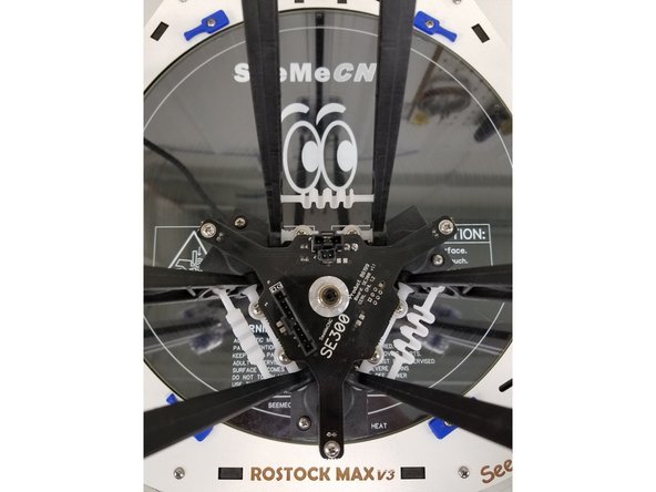
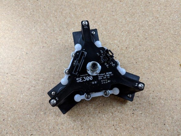
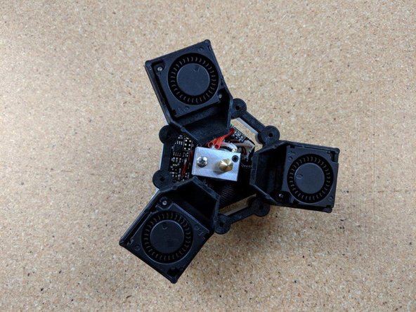
You will need to have your SE300 Hot End assembled. For instructions on how to assemble your SE300 click here.
-
You will also need to have your "SE300 Whip" assembled. For instructions on how to assemble your Whip click here.
-
-
-
NOTE: This guide is intended to be followed online in order to fully utilize the links and documentation found within.
-
First, click here to read safety information. This safety information may be updated at anytime so occasionally check for updates.
-
Open and inspect the contents of your v3.2 Upgrade kit to ensure you have all the parts listed on the BOM.
-
If at any time you find you are missing parts are have a defective component, please submit a support ticket with SeeMeCNC.
-
-
-
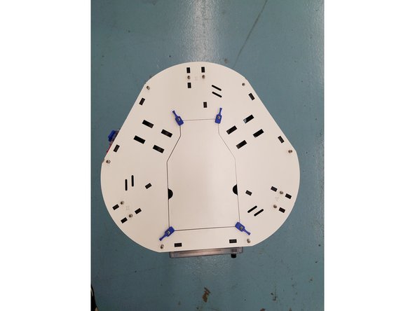
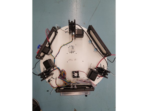
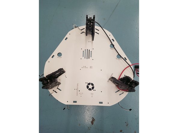
The first step is removing the top laser cut panel from your machine. Unscrew the 12, 6-32 1" L screws around the border. Then lift off the top panel exposing your Rambo Board, Steppers, ect.
-
Be careful not to damage your Top plate while removing it. Its best to slowly work your way around the board pulling upwards.
-
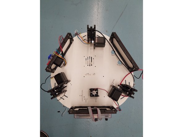
Remove the 3 black laser cut acrylic pieces by pulling them upwards.
-
Be sure you keep all the hardware you remove from the machine in a safe place where you will be able to find when its time to reassemble.
-
-
-
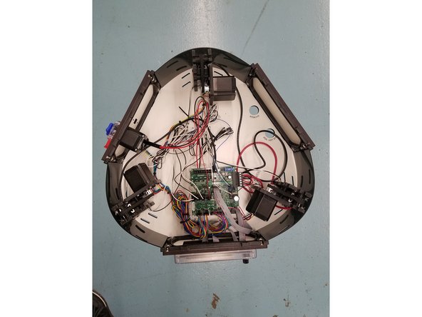
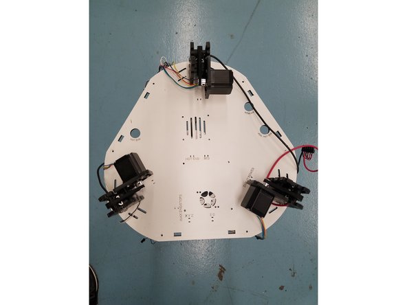
Unplug all connectors going into the Rambo Board including the LCD adapter and ribbon cables.
-
Next unscrew the 4 nylon standoffs holding the Rambo Board up. You will want to hold the standoff in place with one hand, while unscrewing it with the other from the bottom of the Laser Cut Plate.
-
-
-
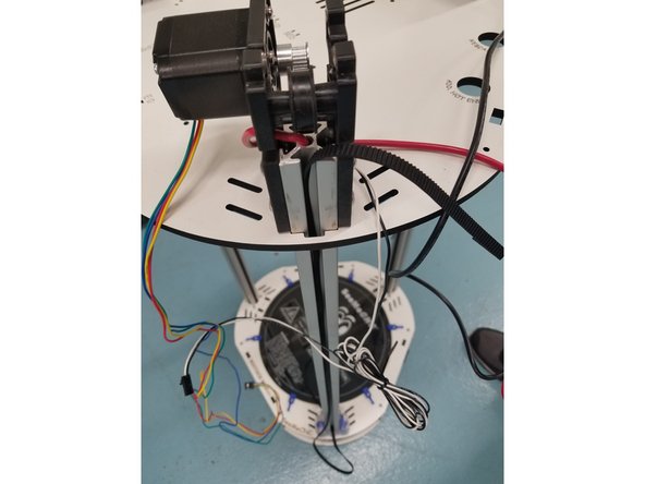
Next step is removing the Zip ties used to tame your wires and uninstalling the whip.
-
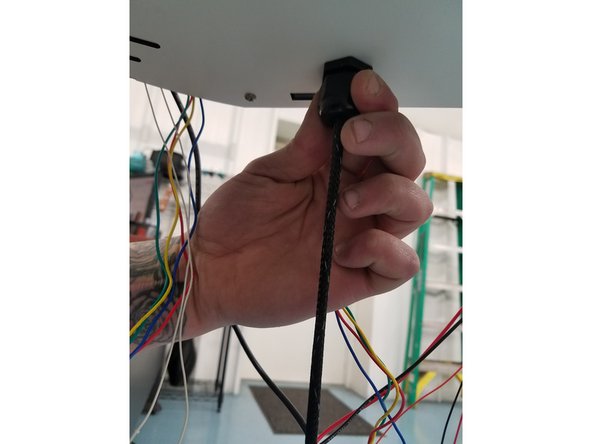
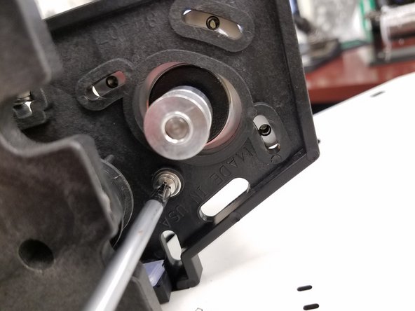
After cutting the zip ties, you will need to uninstall the whip. To do this Grab the black plastic Cable Mount Hub on the bottom side of the Laser Cut Plate and turn it counter clockwise until you feel the start to fall through.
-
You can remove the entire Cable Mount Hub if you would prefer. To do this, hold the top and bottom of the Hub and turn the plastic nut on the top side of the Laser Cut Plate until it has spun free from the bottom half
-
KEEP 40MM COOLING FAN FOR LATER USE!
-
-
-
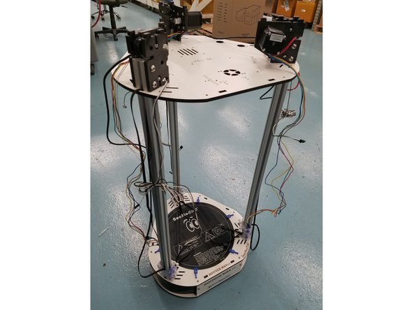
Next Step is removing the laser cut and injection molded side panels from the Laser Cut Plate.
-
First, unscrew the 10-32 x 5/8"L bolts holding the laser cut side panels to the injection molded side panels. There will be 6 in total
-
Second, unscrew the 6-32 1"L screws from the injection molded side panels. There will 6 of these screws located on the bottom of the Laser Cut Panel
-
Again be sure and keep all hardware the you remove from the machine as you will need it when its time to put it all back together.
-
-
-
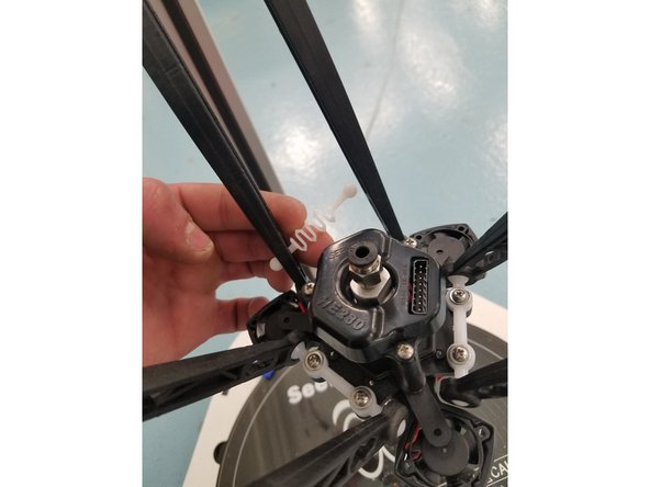
The Next step is removing the Hot End and Injection Molded arms. To do this start by removing the 3 white plastic springs located near the Hot End.
-
Now you can remove the Injection molded arms from the acetyl ball joints attached to the Hot End.
-
Repeat the same steps with the springs, arms, and acetyl ball joints attached to your carriages.
-
CAUTION: The white springs can get brittle over time. Do not try and overstretch them.
-
-
-
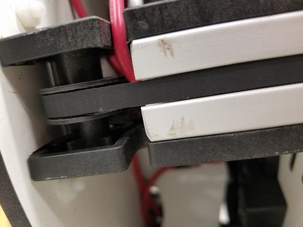
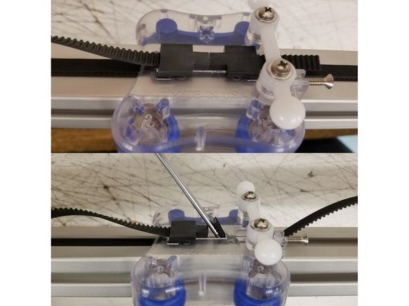
The Next step is removing the top belt clamps from the carriages. To do this take a flat head screw driver and wedge it under the Belt Tension Clamp. Once you have the flat under the clamp you want to give it a counter clockwise quarter turn until the clamp pops free of the carriage.
-
DO NOT REMOVE BOTH BELT CLAMPS FROM THE CARRIAGE. This will make re-installing the belts easier later.
-
Once you have the belt removed from the carriage you can pull the belt from the top until it clears the timing pulley and idler bearings. Now you can let it hang off the back side of the rail for later use.(see 3rd picture)
-
Repeat step for each Tower.
-
-
-
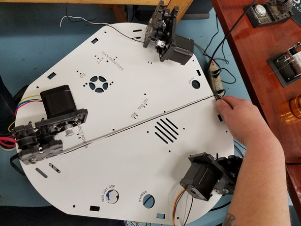
Next step is removing the Timing pulleys from the stepper motor. To do this you will need a 2mm Allen wrench. Loosen the two set screws on each Timing pulley until they are backed out enough to pull the Timing Pulley off the stepper shaft. Do this on all the 3 motors
-
IF YOU DID NOT PURCHASE NEW STEPPER MOTORS FOR YOUR UPGRADE YOU WILL NOT NEED TO REMOVE YOUR MOTORS.
-
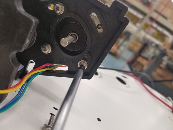
IF YOU PURCHASED NEW STEPPER MOTORS: Remove the old motors by unscrewing the 4 machine screws from the injection molded motor mount.
-
-
-
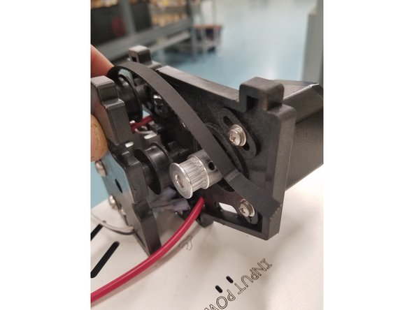
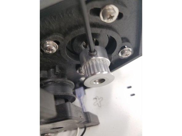
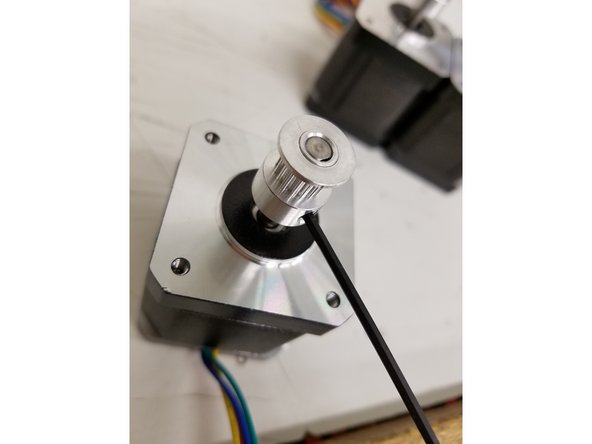
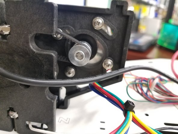
Next Step is installing the new 16tooth Timing Pulleys. Use the photo on the left as a reference on where to tighten down the pulley to the stepper shaft. Use a 2mm Allen Wrench to tighten the set screws. MAKE SURE TO TIGHTEN THE SET SCREW ON THE FLAT OF THE STEPPER SHAFT FIRST.
-
When installing the new Stepper Motors, tighten down the machine screw closest to the endstop switch all the way. Leave the other 3 machine screws slightly loose so the stepper motor can still rock back and forth in the injection molded motor mount.
-
SEE VIDEO IN NEXT STEP FOR REFERENCE
-
-
-
This video shows what your stepper motor should look like with new timing pulley installed and also shows the range of motion you should have for belt tension later in the guide.
-
-
-
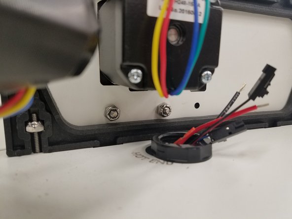
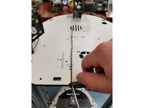
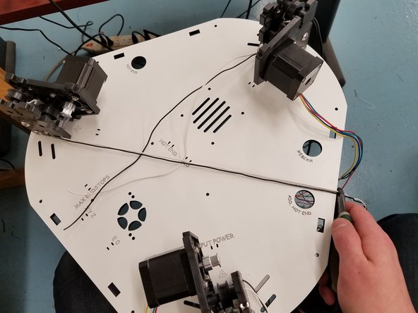
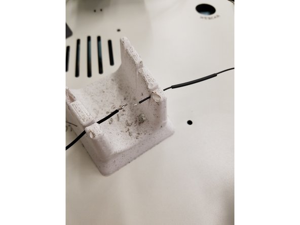
Next step is preparing your end stop wires for the Duet3D-WiFi board. Start by trimming the wires down to length. Pull the wires to the opposite edge of the Laser Cut Plate and snip the off excess.
-
Do Not Worry if your end stop wires are not long enough to be cut to that length. You will soldering on new end stop leads that will be plenty long enough.
-
-
-
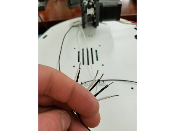
In this step you will strip the ends of the existing end stop wires so that they can be soldered to the new KK crimped end stop wires included in your pack.
-
Strip back the existing end stop wire while being careful not to damage or cut to deep into the wire.
-
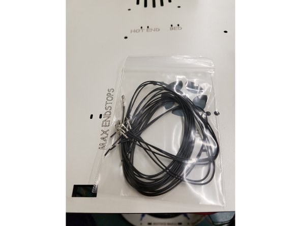
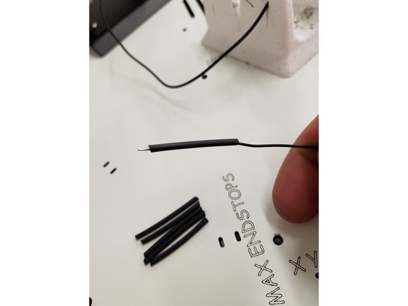
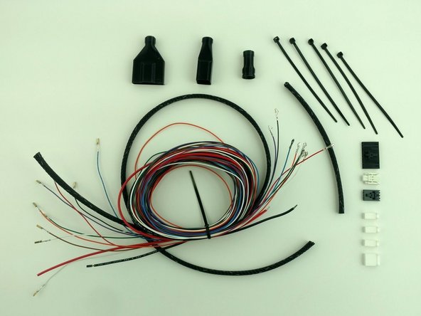
Remove your new end stop wires from the pack along with the 8" length of 1/16th heat shrink. Your new end stop wires are already stripped back for you.
-
Cut the 8" long 1/16th heat shrink down into 6 even as possible lengths and put it on the 6 new end stop wires
-
-
-
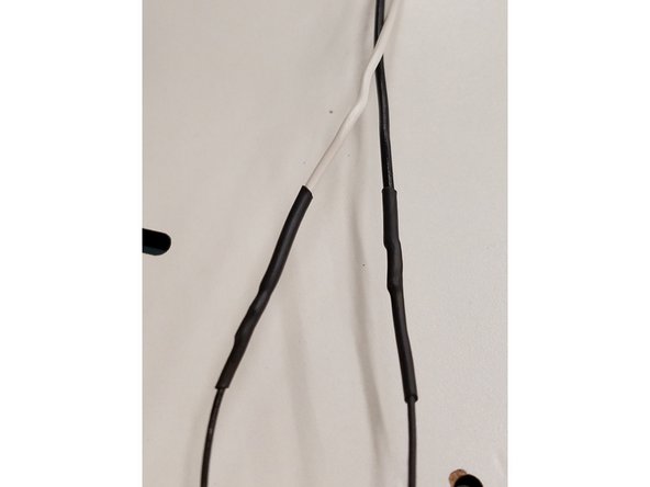
Pre-tin each wire and make sure you have added the heat shrink. Once you have done that, you are ready to join the wires.
-
BE VERY CAREFUL NOT TO BURN YOURSELF OR THE WIRE CASING WHILE SOLDERING!
-
Solder the new End Stop Wires to the Existing.
-
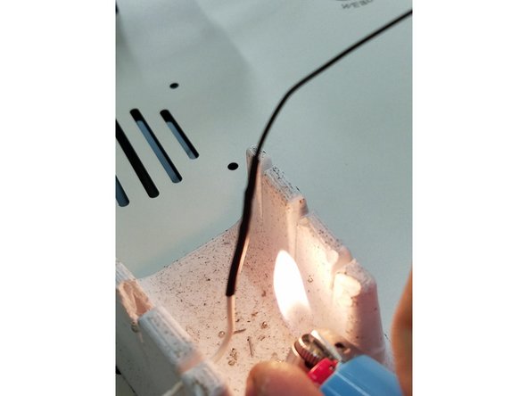
Once that Solder joint has cooled down slide the heat shrink over the joint and apply heat being mindful not to let the heat stay in one spot for too long
-
-
-
Watch this video for instruction on how to install the KK connector.
-
It is a 4pin connector in the video but you will be installing a 3 pin for the end stops.
-
-
-
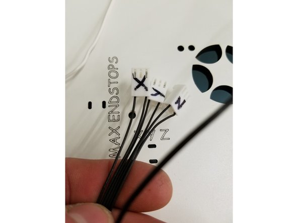
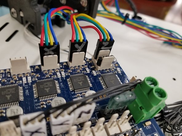
Install the wires one tower at a time with one KK crimp going into the first Pin of the connector and the other going into the 3rd. Repeat this with all end stop wires.
-
After you have installed the end stop wires into the 3 Pin connector it is a good idea to mark which tower they go to by writing X,Y,Z on the connectors
-
End Stop Wires have no polarity so it does not matter which wire goes into which spot. As long as they are in the first and third Pin.
-
-
-
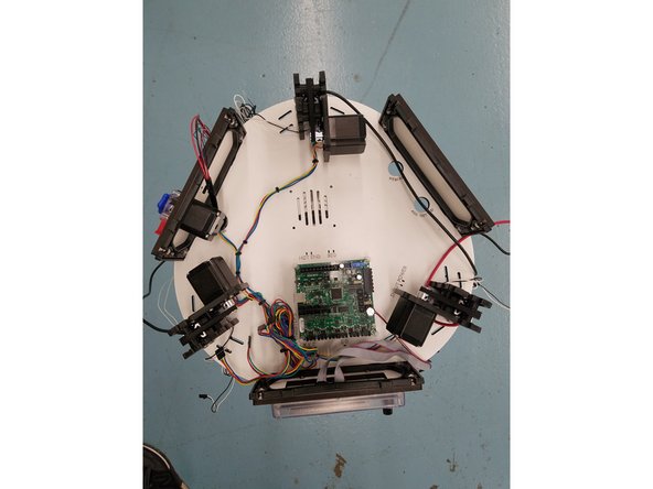
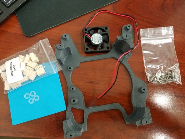
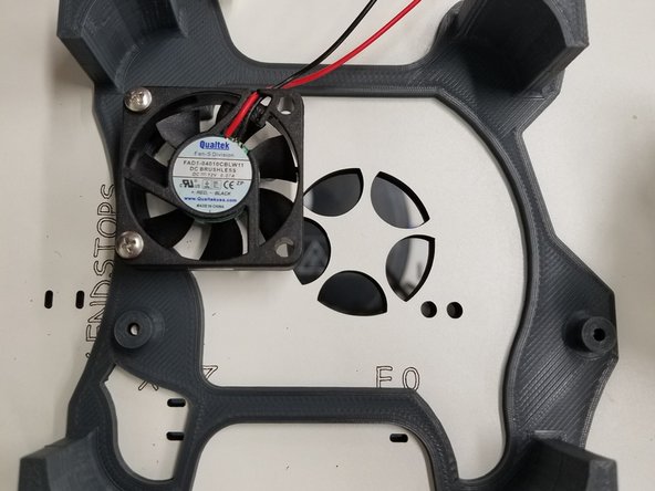
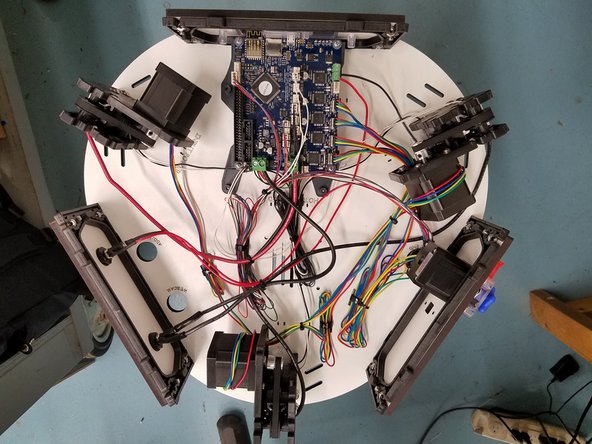
The next step is installing the 3D Printed Duet Standoff. For this step you will need the 40mm fan you previously removed from under the Rambo, your 3D printed Duet standoff, the small hardware bag containing 10 screws, and the 4 Nylon washers from the Duet Connectors bag located in your Duet WiFi box.
-
-
-
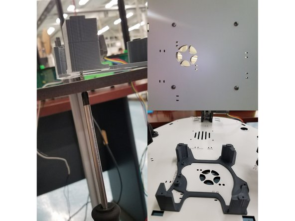
Begin by lining up your 3d printed standoff with the existing Rambo standoff screw holes. Use the 4 #6x1/2"L screws provided and screw them up into the standoff from the bottom of the Laser Cut Panel.
-
Now install the 40mm fan to the 3d printed standoff using the 2 M3-.50x14mm screws.
-
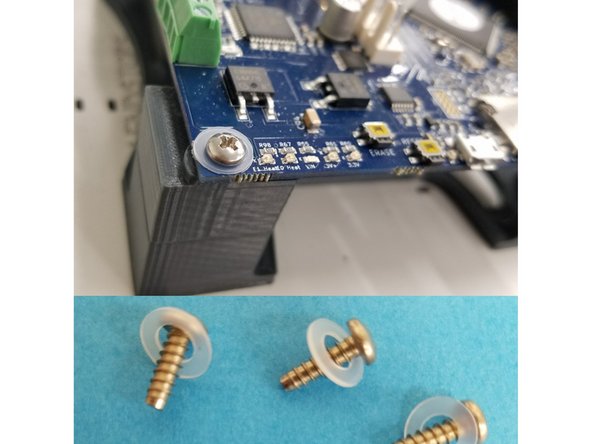
Now line up your Duet Wifi board with the 4 top holes of your 3d printed stand off and tighten it down using the four 3/8" pan head screws and four Nylon washers. Do your best to keep the board as centered as possible.
-
BE CAREFUL NOT TO OVER TIGHTEN ANY OF THE SCREWS INTO THE 3D PRINTED STANDOFF.
-
-
-
-
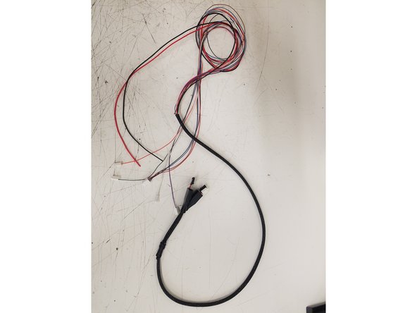
Once the whip is assembled you can advance to the next step.
-
-
-
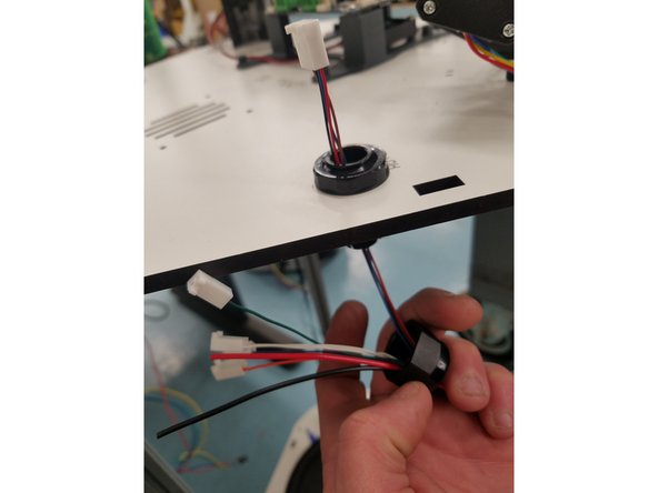
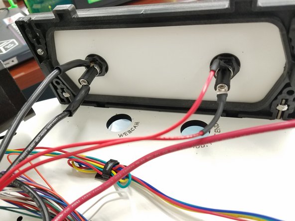
Begin by unscrewing the bottom part of the Cable Mount Hub and threading all the wires from the SE300Whip through it.
-
Now push the 4pin connector through the top half of the Cable Mount Hub still attached to the Laser cut Panel.
-
THREAD THE 4PIN CONNECTOR THROUGH FIRST AS IT WILL BE A TIGHT FIT AND YOU DONT WANT TO DAMAGE ANY OF THE OTHER WIRES.
-
Once the 4pin connector is through, you can thread the rest of the whip up through the Cable Mount Hub.
-
-
-
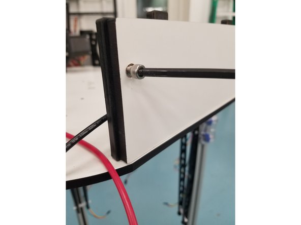
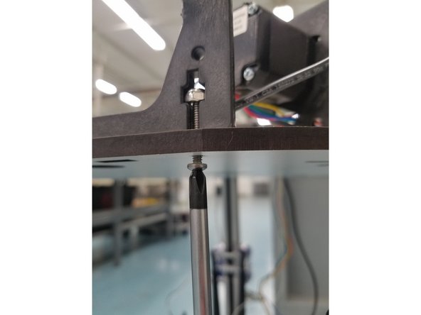
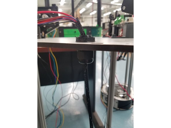
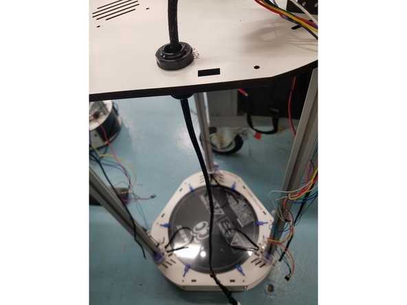
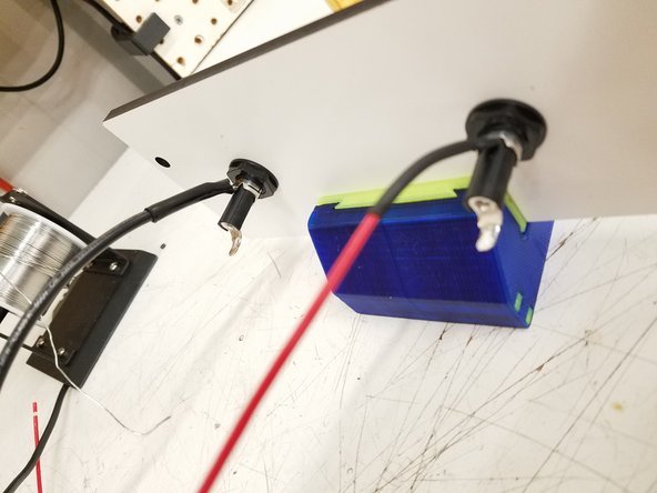
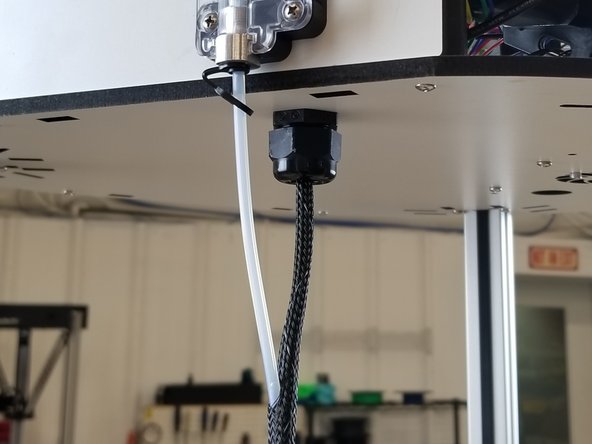
You will now need to set the whip length and tighten the cable mount hub.
-
The Hot End connector end of the whip should almost reach the bottom of the enclosure when in the Cable Mount Hub.
-
You will tighten the cable mount hub at that position so the whip's length is fixed.
-
-
-
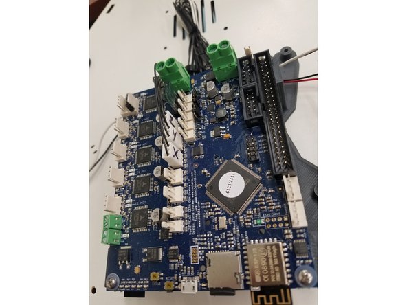
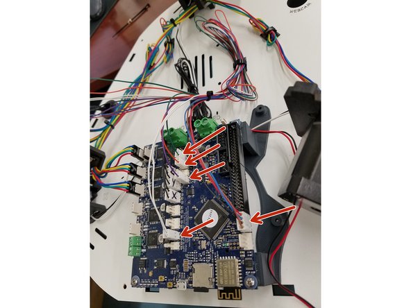
Image one shows the common terminal locations on the Duet board. Please reference this when preparing for wire installations.
-
When inserting the wires in the white Molex KK connectors, make sure you're using the connectors we sent you in the kit, NOT the ones included in the Duet box!
-
We will begin with the End Stop Wires. You must ensure that you get the correct end-stop plugged in with the corresponding location on the Duet Board. If not we will run into issues during later setup.
-
Then Secure the End Stop wires with a cable tie
-
-
-
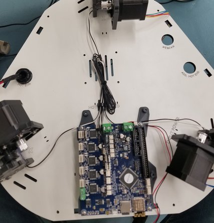
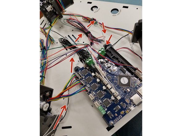
In this step you will connect your stepper motors to the Duet WiFi board.
-
Install the motor wires in the locations indicated here. You can route the wires however you like, just be sure not to run them parallel to the End Stop wires.
-
Make sure the motor connectors are facing the proper direction, with the red wire facing the front of the machine.
-
-
-
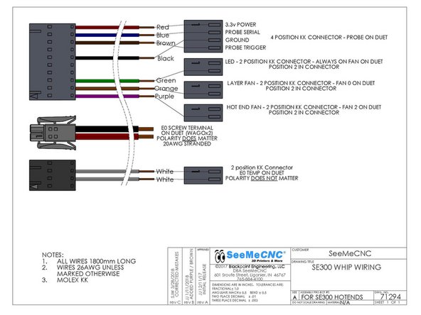
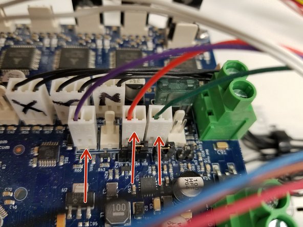
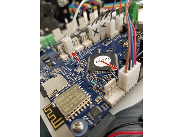
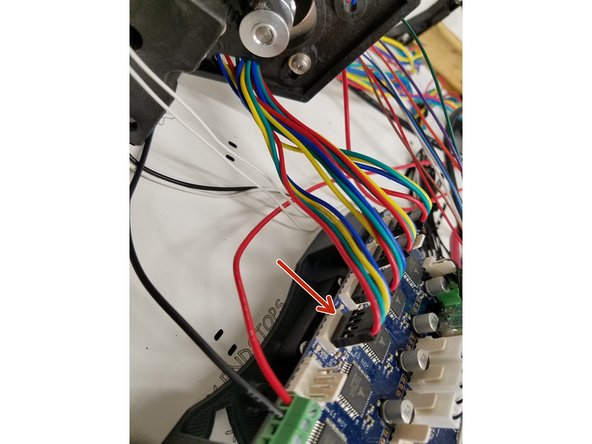
Install E0 TEMP (2 white wires in a 2 pin connector) connector in the location E0 TEMP position on the DUET board.
-
Install the HOT END FAN (1 purple wire in a 2 pin connector) connector in the FAN 2 position on the DUET board.
-
Install the LAYER FAN (1 orange wire in a 2 pin connector) connector in the FAN 0 position on the DUET board.
-
Install the LED (1 green wire in a 2 pin connector) connector in the Always On Fan position on the Duet board.
-
Install the PROBE Wires(red, blue, black and brown wires in a 4 pin connector) connector in the PROBE position on the Duet board.
-
-
-
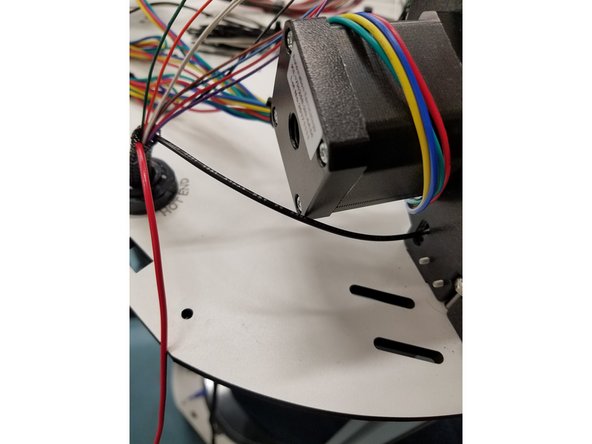
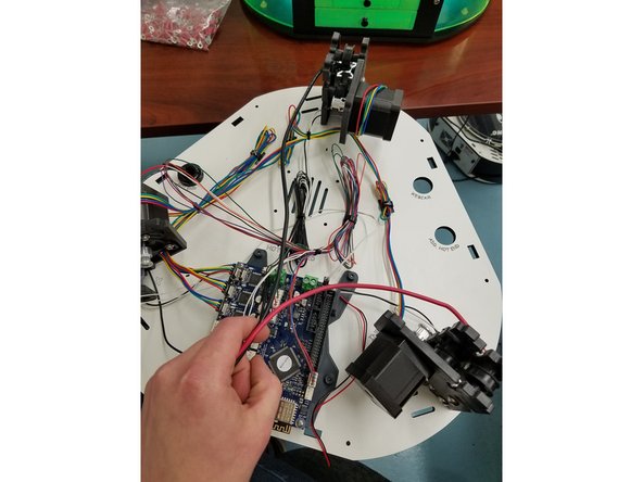
Thread the Black 20awg negative power wire from the Hot End Whip through the injection molded motor mount on the X tower. Cut it to length and strip back the wire about 2mm.
-
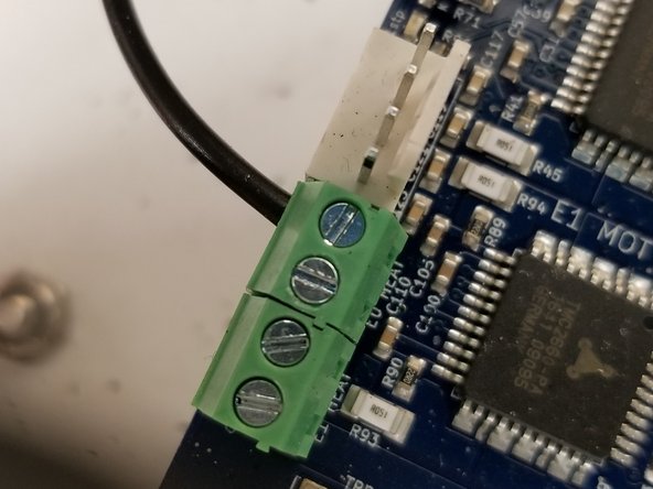
The black 20awg wire from the hotend whip can now be attached to the terminal block as indicated in the photo. You may need to rotate the screw counter clockwise before inserting the wire to open the terminal, as it may be closed from the factory.
-
The Bed Thermistor can be ran as shown in the pictures. If your Bed thermistor leads are not long enough to make that travel. You can just run it over the board and plug it in.
-
The Bed Thermistor wire will still have the SL Crimp connector attached. So it will only plug in one way. There is no polarity in Thermistor wires.
-
You can change the connector to one of the 2pin connectors provided in the Duet Connectors bag. But this require installing KK crimps and that can be difficult to get right without the proper tool. It will work fine with the existing SL 2pin though.
-
Make sure the green terminal block DOES NOT twist, it could rip off and cause you to replace your entire Duet! You may need to CAREFULLY hold it with pliers while tightening the screw.
-
-
-
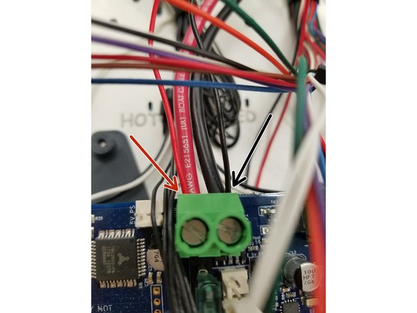
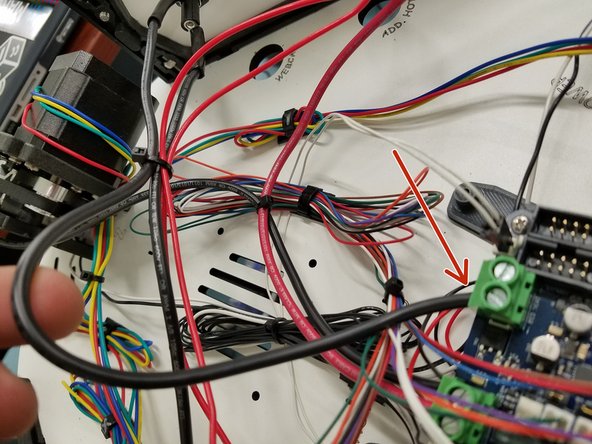
Now install the black 12awg wire from the Z tower, and the red 12awg wire from the Y tower in the locations indicated here.
-
In the same Plug install the Positive and Negative leads from the 40mm cooling fan under the Duet Board. (SEE PICTURE)
-
You can cut these wires to whatever length you would like, just make sure they are not too tight or straining the Duet Connector.
-
Make sure the green terminal block DOES NOT twist, it could rip off and cause you to replace your entire Duet! You may need to CAREFULLY hold it with pliers while tightening the screw.
-
-
-
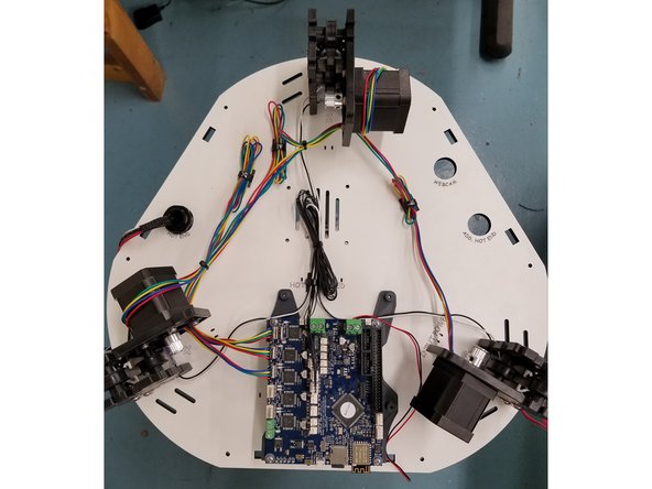
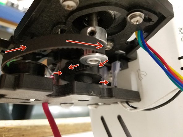
The first image shows an overview of the belt route for each tower assembly.
-
For the next step you will want to lay the printer on its side. Being careful not to pinch the SE300 Whip or the two remaining uninstalled wires. Also remove the 3 pieces of black acrylic from the base.
-
-
-
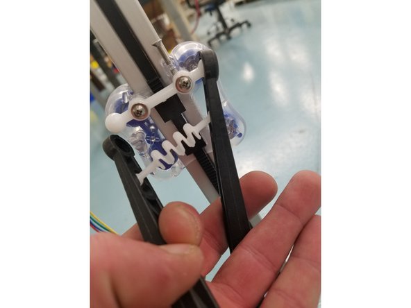
Thread the belt back up the tower and over the top idler bearing and back into the other side of the tower. Now pull the belt up over the timing pulley and it should look like the first picture.
-
Make sure the belt is on the base idler bearing.
-
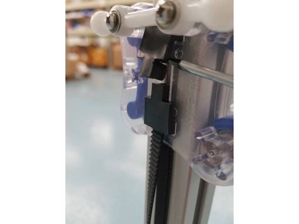
Now thread the belt through the top of the carriage and ramp it up through the hole with a small flat head screw driver. Once you enough belt through the carriage to clamp, install the Belt Clamp that you removed in the beginning. Do this for all three towers.
-
Do not worry if your belt is loose, you will tension them in the next step.
-
-
-
To Tension the belts push the motor forward in the injection molded mount while feeling the belts. Once you have reached the desired tension. Tighten down the 3 screws that were left loose.
-
You do not want the belts too tight or too loose. Most importantly you want them all evenly tensioned. Arrange the 3 carriages so they are at the same height on the rails and do your best to match the tension on each belt.
-
-
-
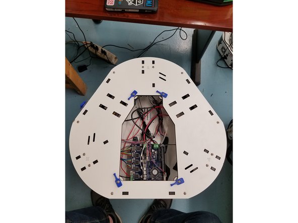
Using the same 6-32 x 1" L screws you removed from the panels in the beginning. Screw the 3 Injection Molded Side Panels back in to the Laser Cut Melamine.
-
-
-
NOTE: Conversion kits shipped after 09/18/2018 DO NOT include the fuse holders and fuses as the fuses are now built into the Duet board and these are no longer needed.
-
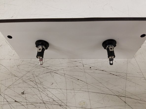
The Fuse holders in your kit already have the fuse inside of them. You will need to open the Fuse holder to see which one contains the 5A Fuse and 15A fuse.
-
Install them into the corresponding laser cut holes on the side panel.
-
Now Pre-Tin the 4 prongs on the back side of the Fuse holders and one end of the 12awg black wire and one end of the 18awg red wire found in your kit. Also cut the two lengths of heat shrink in half.
-
-
-
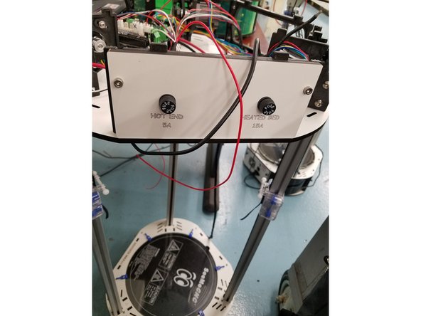
Solder the 18awg red wire and 12awg black wire from the kit to the top prong on the fuse holders and heat shrink the solder joint.
-
Install the Fuse Panel on the injection molded side panel between the Y and Z towers.
-
DO NOT LET THE SOLDERING IRON REST ON THE FUSE HOLDER TOO LONG OR YOU COULD DAMAGE IT AND NEED A REPLACEMENT!
-
Now solder the 20awg red wire from the hot end whip to the bottom prong on the 5A HOT END Fuse. Next solder the 12awg black bed heat wire coming out of the X tower to the bottom prong of the 15A BED HEAT fuse.
-
DO NOT FORGET TO PUT YOUR HEAT SHRINK ON BEFORE YOU SOLDER TO THE FUSES.
-
NOTE: Conversion kits shipped after 09/18/2018 DO NOT include the fuse holders and fuses as the fuses are now built into the Duet board and these are no longer needed.
-
-
-
Conversion kits shipped after 09/18/2018 will have the wires mentioned go directly to the locations listed in this step, rather than from the fuse holders as the fuse holders are no longer used in the kit since the Duet has the fuses built into the board.
-
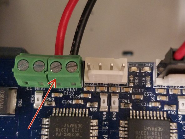
Install the 18awg red wire coming from the 5A HOT END FUSE into the screw terminal on the Duet Board as shown in the picture.
-
Install the 12awg black wire coming from the 15A HEATED BED FUSE into the larger screw terminal on the Duet Board as shown in the picture.
-
Make sure the green terminal block DOES NOT twist, it could rip off and cause you to replace your entire Duet! You may need to CAREFULLY hold it with pliers while tightening the screw.
-
-
-
Install the EZR plate using the SHCS 10/32 cap screws on the side panel between the X and Z towers.
-
Plug in the extruder motor the same way you did with the motors, in the next available position on the Duet.
-
-
-
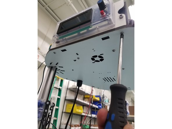
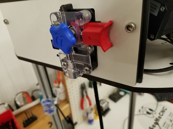
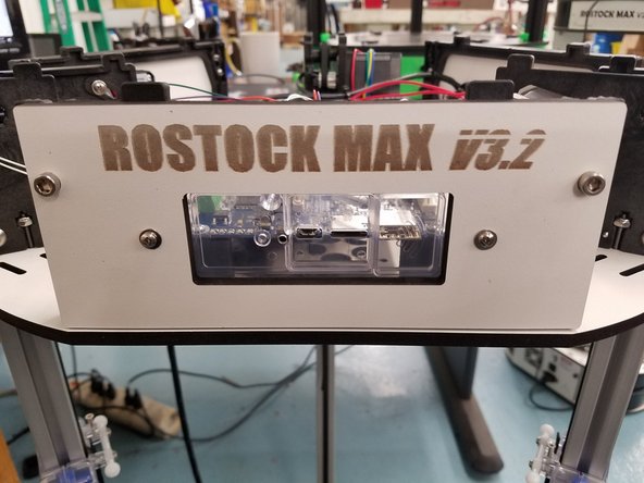
Screw the clear injection molded Duet cover to the laser cut melamine name plate.
-
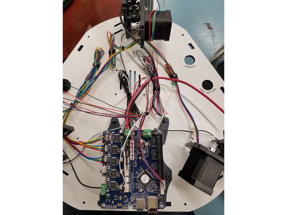
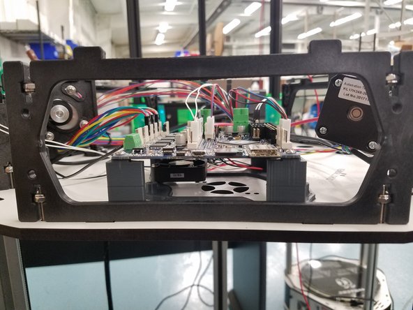
Install the name plate onto the front injection molded side panel. You can adjust the placement of the clear injection molded Duet Cover or your Duet Board to perfectly align the slots for SD card and Reset button.
-
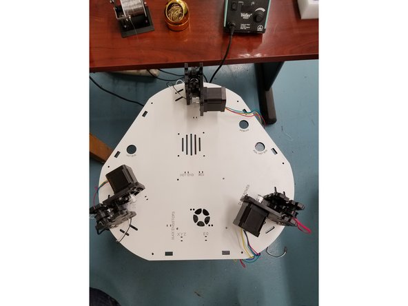
At this point your machine should look like the 3rd picture in this step.
-
-
-
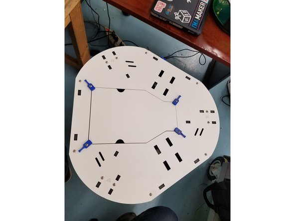
You are now done with the wiring and can re-install the top laser cut plate.
-
Install the top plate using the same 6/32 1" L screws you removed in the beginning. Screw them into the captive nylon lock nuts in the injection molded motor mounts and side panels.
-
-
-
Start by attaching the arms to the Carriage Ball Joints and then install the springs into the arms. Repeat this on all 3 towers.
-
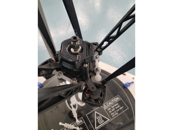
Now you can install the SE300 Hot End onto the arms in the orientation featured in the photo attached.
-
BE CAREFUL NOT TO STRETCH THE SPRINGS TOO FAR!
-
If it makes it easier you can install the bottom springs after attaching the Arms to the Hot End Ball Joints.
-
-
-
All upgrade kits ship with an assembled and tested SE300 from the factory. No alterations are necessary.
-
If the kit was purchased prior to all SE300 being assembled please use this: For SE300 Hot End Build Guide Click Here.
-
Once you have assembled the SE300 Hot End you can advance to the next step.
-
-
-
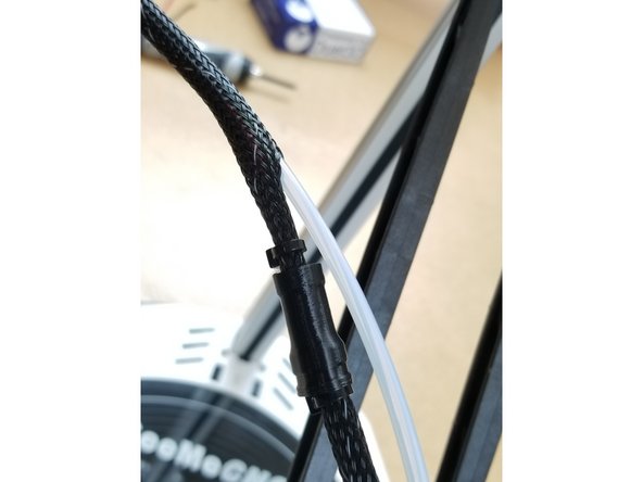
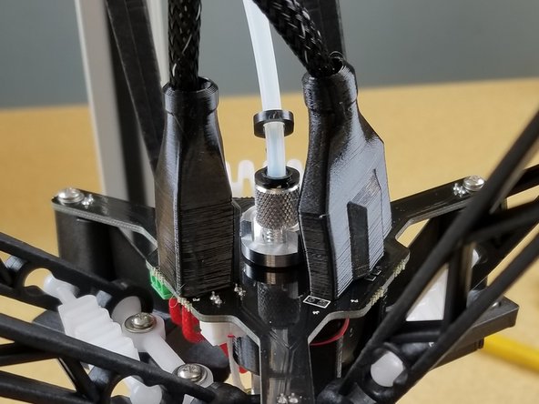
Insert PTFE here.
-
Exit the PTFE tube just before the y-splitter 3D printed part on the whip.
-
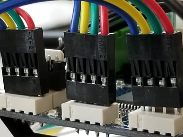
Plug in all three SE300 connectors and slide the 3D printed connector covers in place.
-
BE SURE YOUR PTFE TUBE IS FULLY SEATED INTO THE HOT END AND SECURED WITH THE LANYARD CLIPS PROVIDED ON BOTH ENDS! FAILING TO DO THIS WILL RESULT IN HOT END JAMS
-
-
-
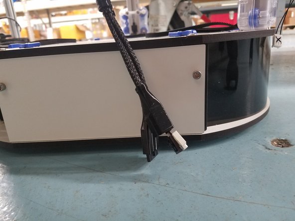
Plug in the power cable to printer.
-
Turn the printer on.
-
The hot end should light up, as well as the status LEDs on the Duet board.
-
We will now move on to the initial connection and setup.
-
Go Here Next > Configuring Rostock Max v3.2
-
If you did not use the 0.9 steppers and/or the 16 tooth pulleys, go HERE to adjust the steps per mm after configuration.
-


![ALMOST THERE! :]](https://d3t0tbmlie281e.cloudfront.net/igi/seemecnc/nNyaWqgy5VWfXJPM.medium)


Cancel: I did not complete this guide.
6 other people completed this guide.