
-
-
For this step you will need the three pieces of TSLOT (the long aluminum bars) that came with your kit and the remaining long lengths of wiring that are in the electronics pack ((2) pieces of 12awg black, (1) 12awg red, and (2) 26awg white wires). You will have one additional 12awg red that is 700mm long, that we will also prepare during this step.
-
Run the wires through the towers as shown. One tower will get both a 12awg black wire and (2) 26awg white wires. If you have difficulty getting the wires through the extrusion, you can thinly tape the white wires to the black wire to assist. Remove the tape when finished.
-
Crimp a yellow ring terminal onto the 700 long red 12awg wire.
-
-
-
The X tower is the extrusion that has the white and black wires running through it.
-
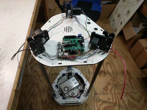
Route the wires through the top base plate as shown.
-
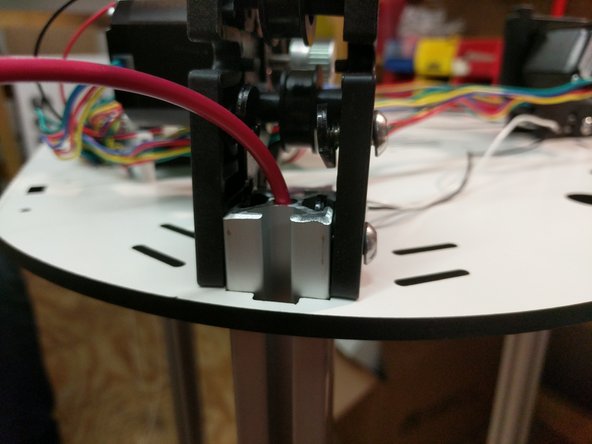
Insert the extrusion into the base top plate, and then through each set of the TSLOT hardware. You will need to have the TSLOT nuts in a vertical orientation to be accepted by the extrusion. You also may need to loosen the TSLOT nuts if you have them too tight.
-
You should not force the extrusion into the assembly. Be careful while working the extrusion down into the plate and through the TSLOT hardware. Too much side-to-side motion can fracture the base plate.
-
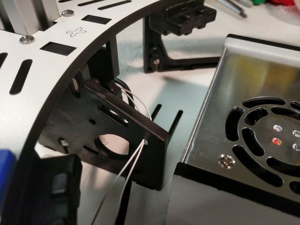
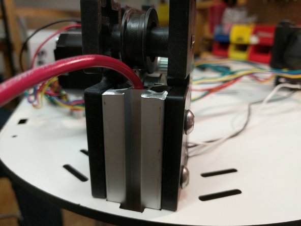
Upon seating the extrusion, you should route the wires around the idler plate as shown and tighten the (4)1/4-20 button head screws.
-
-
-
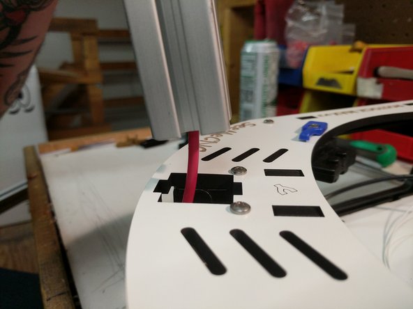
The Y tower is the extrusion that has one red wire run through it.
-
Route the wire through the base top plate as shown.
-
Insert the extrusion into the base top plate, and then through each set of the TSLOT hardware. You will need to have the TSLOT nuts in a vertical orientation to be accepted by the extrusion. You also may need to loosen the TSLOT nuts if you have them too tight.
-
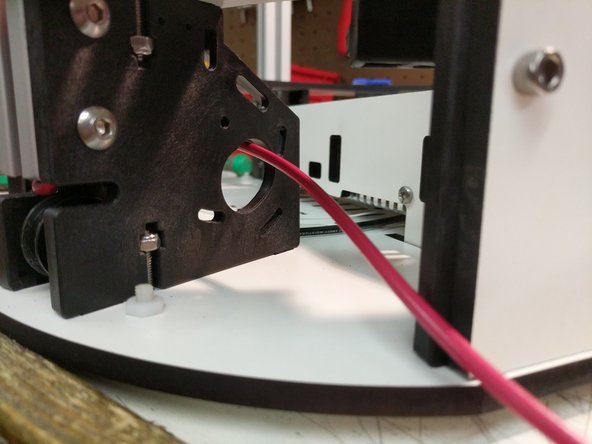
Upon seating the extrusion, you should route the wires around the idler plate as shown and tighten the (4)1/4-20 button head screws.
-
Route the wire as shown.
-
-
-
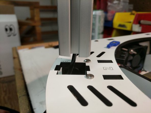
The Z tower is the extrusion that has one black wire run through it.
-
Route the wire through the base top plate as shown.
-
Insert the extrusion into the base top plate, and then through each set of the TSLOT hardware. You will need to have the TSLOT nuts in a vertical orientation to be accepted by the extrusion. You also may need to loosen the TSLOT nuts if you have them too tight.
-
Upon seating the extrusion, you should route the wires around the idler plate as shown and tighten the (4)1/4-20 button head screws.
-
Route the wire as shown.
-
-
-
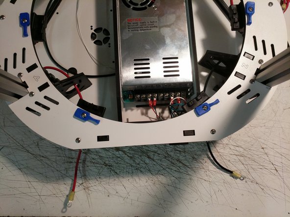
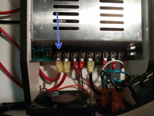
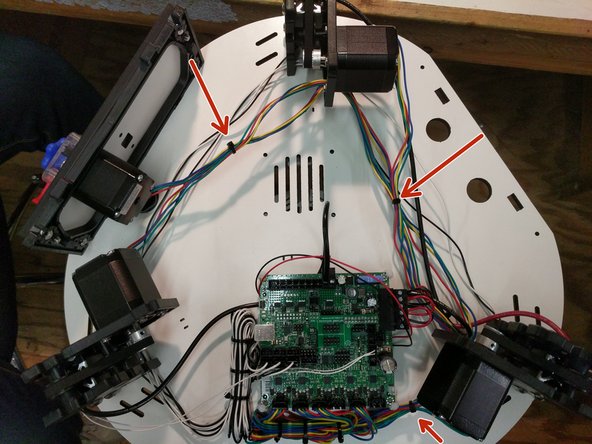
Crimp a yellow ring terminal onto both the black and red wires on the ends that exit the bottom of the Y and Z towers.
-
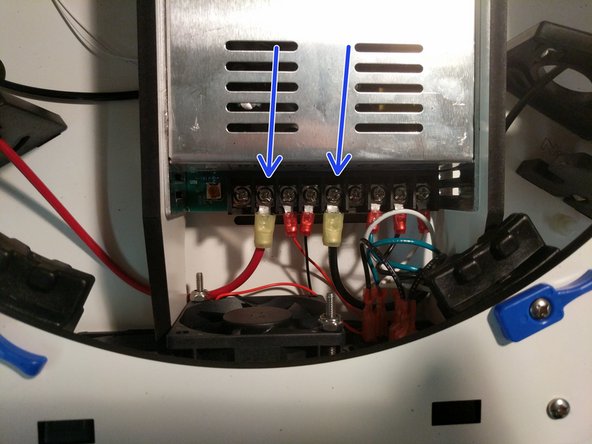
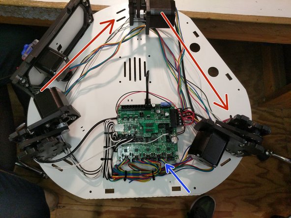
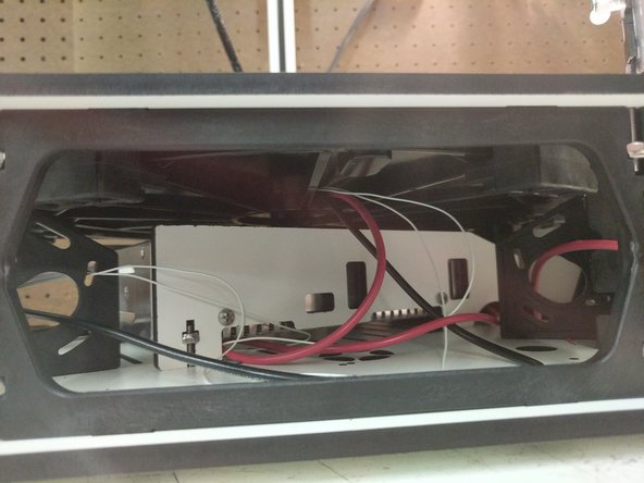
Route them under the large arc of the PSU blocker and attach them to the power supply. The locations are indicated by arrows in the image.
-
-
-
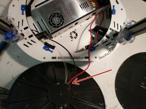
The 700mm long 12awg red wire that you previously crimped the ring terminal on should now be connected to the power supply in the location indicated by an arrow. Route the wire under the PSU blocker with other red 12awg wire.
-
-
-
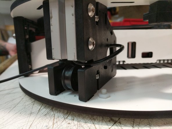
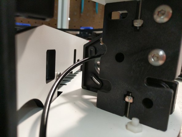
The images for this step show the installation of the ball joints and end stop striker on the carriages after installation on the printer. We will go ahead and install them prior to installing the carriages on the printer.
-
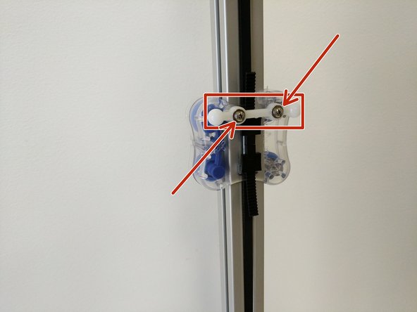
Align the ball joint with the posts on the inside of the carriage and press on. You should attempt to evenly press the ball joint onto the carriage.
-
Secure the ball joint to each post using a #4 washer and a #4 x 1/2" sheet metal screw.
-
Repeat these steps for each of the three carriages.
-
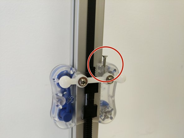
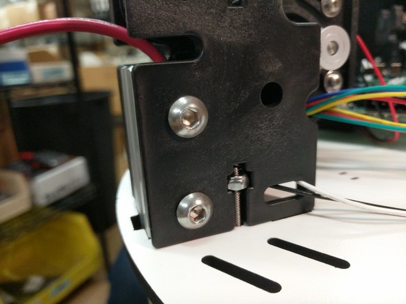
Install the 4-40 x 3/4" screws into the top of the carriage as shown in the image. You should tighten the screw until you start to feel some resistance. At that point STOP and do not tighten any further.
-
This screw is the trigger for the end-stop.
-
-
-
Since the carriages are now fully prepared, you can now install them on the printer.
-
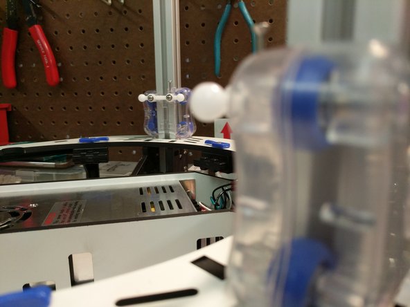
Align one of the carriages with the top of the TSLOT (ball joints facing inside the print area) and gently move it down until all four bearings are engaged by the TSLOT. Roll the carriage to the bottom of the extrusion and let it sit against the top base plate.
-
Repeat for the other two carriages.
-
-
-
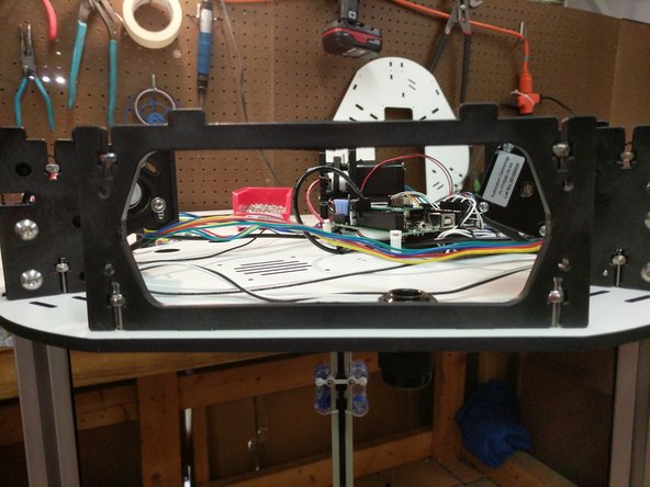
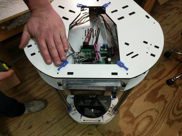
Next we will be installing the top assembly on the printer. It is most helpful if you can get assistance from someone, but this can be completed by yourself.
-
Orient the top assembly correctly with the base assembly (XYZ)
-
Route the towers from X Y Z up through the laser cut base of the top assembly.
-
Align the cutouts for the extrusion in the laser cut plate with the actual extrusions. You should not push the top assembly down any farther yet.
-
-
-
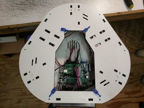
You will now need to work around the machine, one tower at a time aligning the TSLOT nut in a vertical orientation and slowly working down the top assembly. You will ultimately go around doing this process several time to work the top assembly down.
-
Do not force the top assembly down or you risk damaging the components.
-
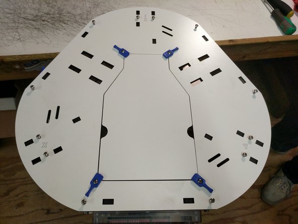
Continue this operation until the top assembly is resting on the extrusion stops (molded into the injection molded pieces).
-
-
-
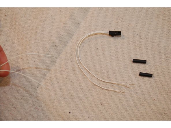
Locate the thermistor leads that are included in the Rambo accessories bag. It's two white wires with a small 2 pin keyed connector on it.
-
Cut about 3" off the thermistor leads from the connector end. You'll be soldering this end to the thermistor leads that are coming out of the X tower.
-
Cut the remaining length of 1/8" diameter heat shrink in half.
-
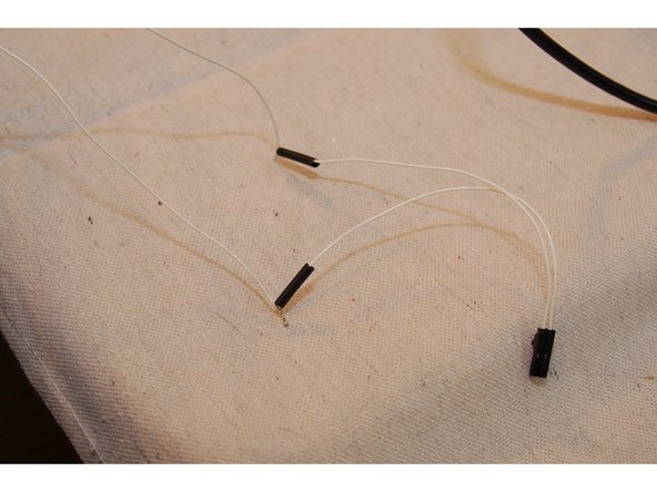
Strip about 1/2" of insulation from each wire.
-
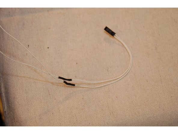
Slip one section of heat shrink over each wire and then solder them together.
-
Slide the heat shrink tubing over the exposed splice and shrink it using a lighter or heat gun. BE CAREFUL!
-
-
-
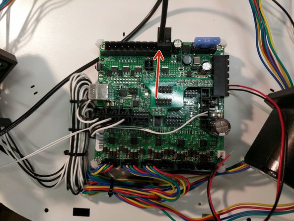
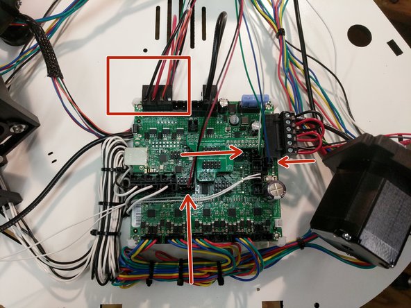
Connect the thermistor wires that you prepped in the last step to the T2 location on the RAMBo board.
-
Locate a 2 position terminal block from the RAMBo kit. You will install the 12awg wire into that connector in the position indicated in the image. This is the negative position on the RAMBo board.
-
Connect the terminal to the RAMBo in the Heat 2 Bed position.
-
Secure the wire to the top assembly base plate.
-
-
-
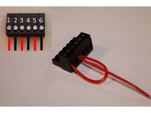
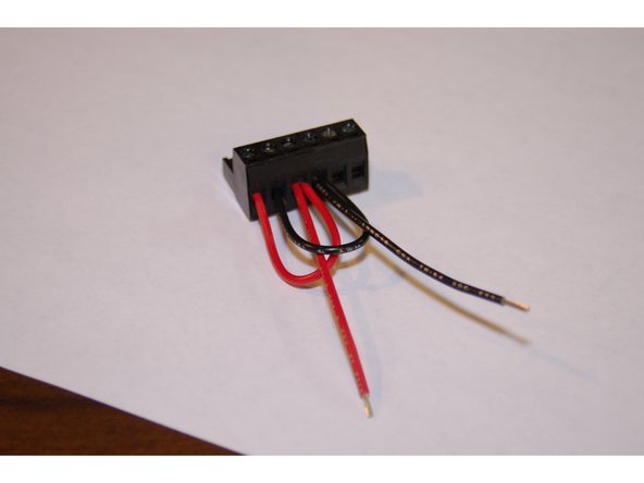
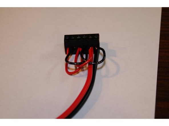
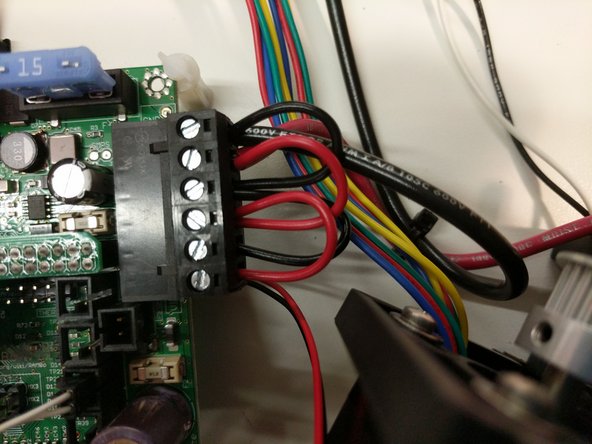
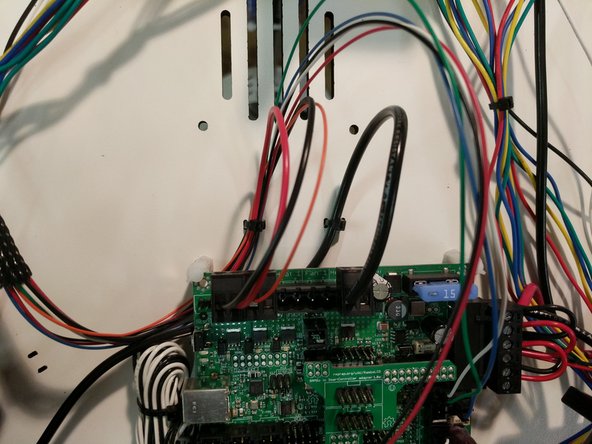
Two pairs of 50mm long, 18ga red & black wires are required for this task.
-
Remove the insulation from the pre-stripped 50mm, 18ga red & black wires and insert them into the compression terminal at the locations shown. Fully tighten each connection!
-
Positions 5 and 6 also hold the 12ga red & black wires coming from the power supply. up the Y & Z towers
-
-
-
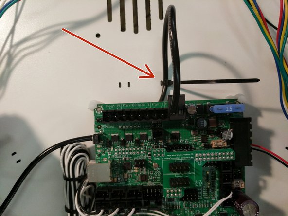
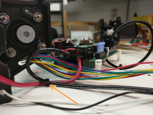
Plug the RAMBo Power Connector into the RAMBo board in the location indicated.
-
Secure the wiring with a zip tie
-
-
-
Routing the belts is best completed by laying the machine down on its side.
-
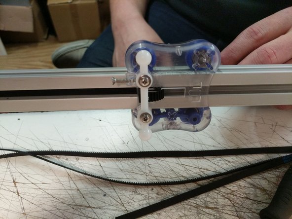
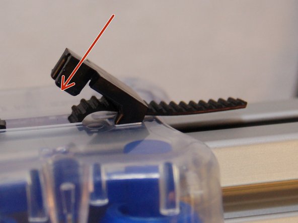
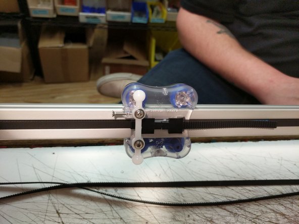
Begin by routing the belt through the top side of the carriage as shown in the first image.
-
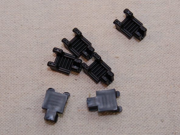
Install a belt clip. The two wider stanced legs will insert into the carriage first and then the belt clip can be pressed down to lock into place. If it is not wanting to lock, you may need to apply inward pressure on the closer stanced legs while pushing down to lock it in place.
-
-
-
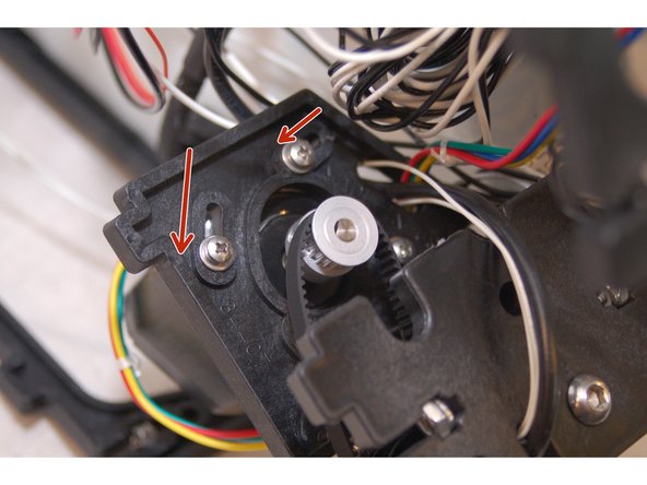
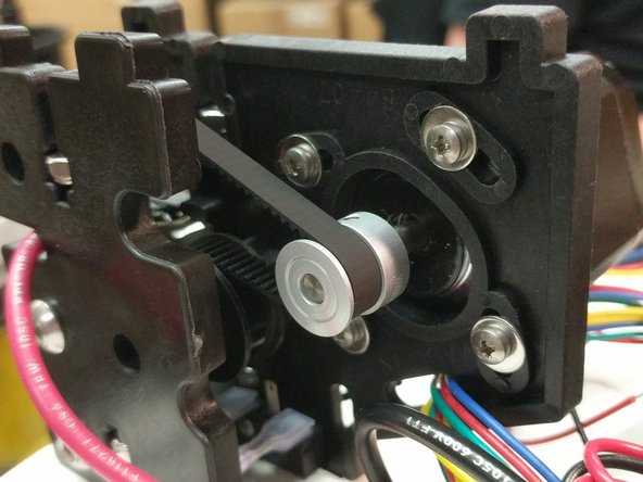
Rotate the stepper motor to the position shown in the photo. This location will give you the most available range of motion for tightening the belts after they are installed.
-
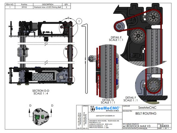
Route the belt as shown in the diagram on step 16
-
Be sure that the belt is not routed on the outside of the frame or carriage pieces! This will prevent motion.
-
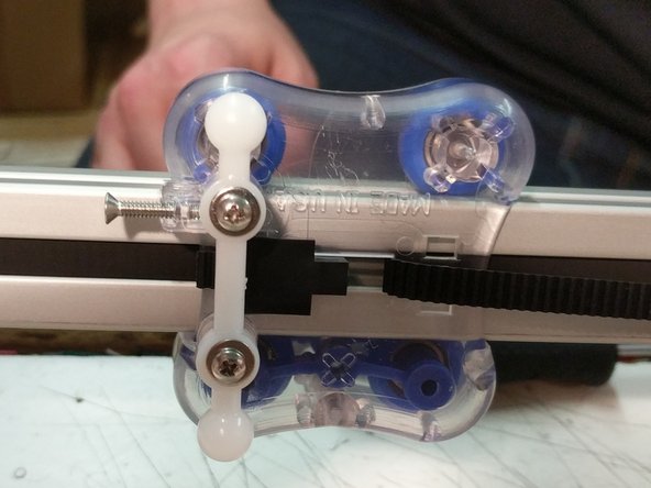
To thread the belt ends into the carriage, use a wire tie or the cut-off from a wire tie to guide the belt up into the belt slot.
-
After you have threaded the belt into the carriage pull the belt end tight - you want to pull all the slack out of the belt.
-
Install the second belt clamp
-
You can trim excess belt, but leave approximately 1" past the belt clip.
-
Complete the routing process for the remaining two towers.
-
-
-
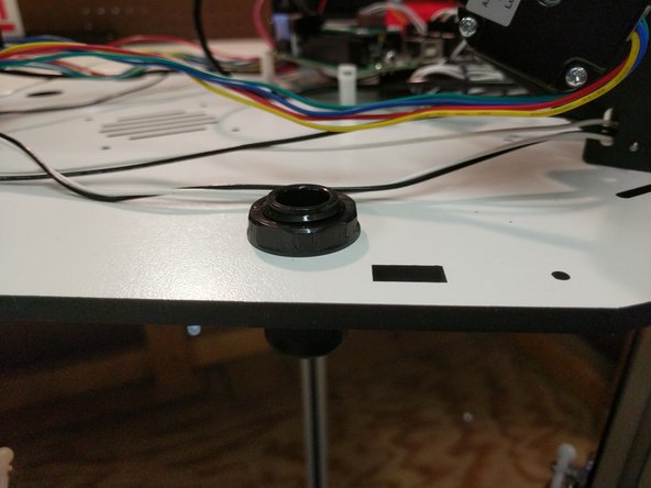
Install the Cable Nut / Whip Assembly in the hole between the X and Z towers. NOTE: In the images provided the whip is not present.
-
Tighten
-
-
-
The belts in the Rostock MAX v3 are tensioned by rotating the stepper motor towards the center of the printer.
-
If you've pulled the belt tight when installing the last belt retaining clip, you only need to add a little more tension to the belt. Rotate the stepper motor so it's about 1/4 the way across the screw slot and tighten all four screws. Do this for each stepper motor.
-
Note that you don't want the belts to be so tight you can pluck them like a guitar string. The more you tighten the belt, the harder the motor has to work in order to move the carriage.
-
-
-
-
Please note that the USB cable shown in the illustration is optional and is not included in the kit!
-
-
-
Insert 6-32 nylon lock nuts into the nut traps on the injection molded base sides.
-
Install the first base side between the X & Z towers.
-
Secure the base side with (2) 6-32 x 1" screws.
-
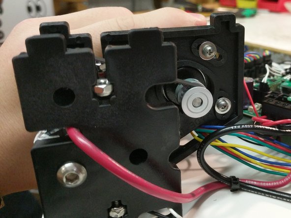
Fasten the EZR Struder side plate to the base side plate using (2) 10-32 socket head cap screws. The holes in the injection molded side panels are not tapped / threaded. Make sure you put some pressure on the screws and keep them straight.
-
Route the wires around the top assembly clockwise as before. You will route through the same locations as the other stepper motor wires.
-
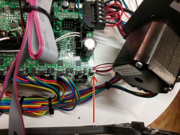
Plug the extruder stepper motor into the E0 location on the RAMBo board.
-
-
-
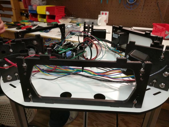
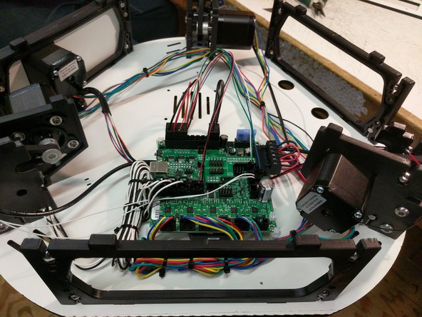
You can clean up the wiring with zip ties to get everything a little more organized. Do not tie your motor and end stop wires together.
-
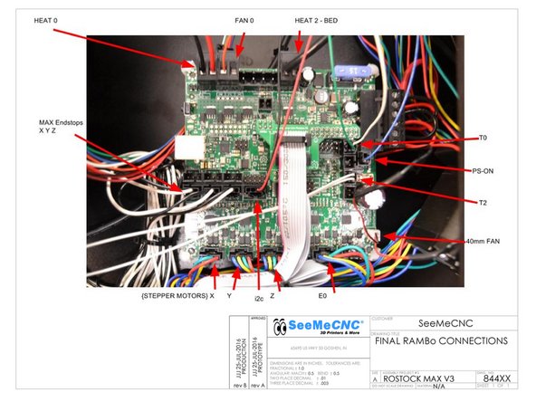
The locations used by SeeMeCNC are noted by arrows in the image.
-
-
-
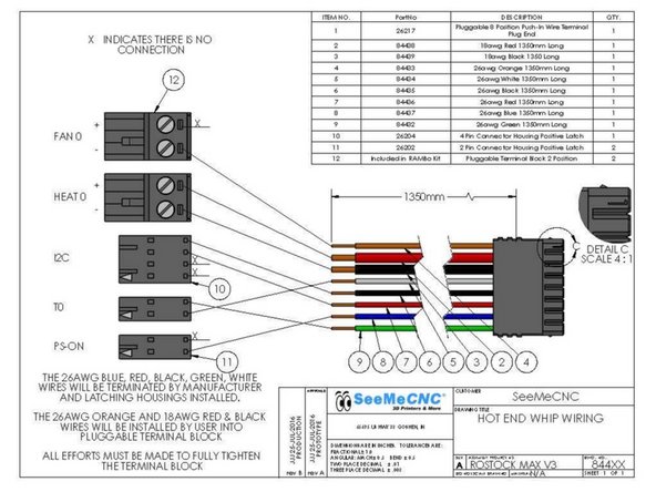
The whip connections specifically are noted below.
-
You should begin by connecting the red and black 18awg wires to a 2 position terminal block (found in RAMBo kit). Note the polarity in the photo.
-
Next, connect the orange wire to a 2 position terminal block (found in RAMBo kit). Note the polarity in the photo.
-
Next, connect the remaining wire to the board. These connection are pre-terminated and connect to the position noted in the pic.
-
Plug in the RAMBo cooling fan. The connection will be made in the bottom right hand corner of the board. This location is indicated in the third image.
-
-
-
The following is a complete overview of the wiring for the RAMBo board. You should review all of your wiring connections and ensure that everything is connected in the correct locations.
-
HE280 power (2 position terminal block with 1 red 18awg & 1 black 18awg wire) goes to Heat 0 terminal ------------- HE280 thermistor (2 position latching connector with 1 white 26awg & 1 green 26awg wire) goes to the T0 position on the RAMBo board
-
Layer Fan power (2 position terminal block with 1 orange 26awg wire (-)) goes to Fan 0
-
Heated bed power (2 Position terminal block with 1 black wire) goes to the Heat2-Bed (-) terminal ---------- Heated bed thermistor (2 position latching connector with 2 white wires) goes to the T2 position on the RAMBo board
-
PS-ON (2 position latching connector with 1 blue 26awg wire) goes to the PS-ON position on the RAMBo board
-
i2c (4 position latching connector with 1 red & 1 black 26awg wire) goes to the i2c position on the RAMBo board
-
Stepper motors connect to stepper motor drivers, labelled X Y Z & E0 ---------- Endstops connect to X Y Z max endstop inputs ---------- 40mm fan connects to 12v AUX output ---------- 12v (6 position terminal block with red and black wires) connects to VIN input on the RAMBo Board
-
-
-
Install the first base side between the X & Y towers.
-
Secure the base side with (2) 6-32 x 1" screws.
-
Repeat for the base side between the Y and Z towers.
-
-
-
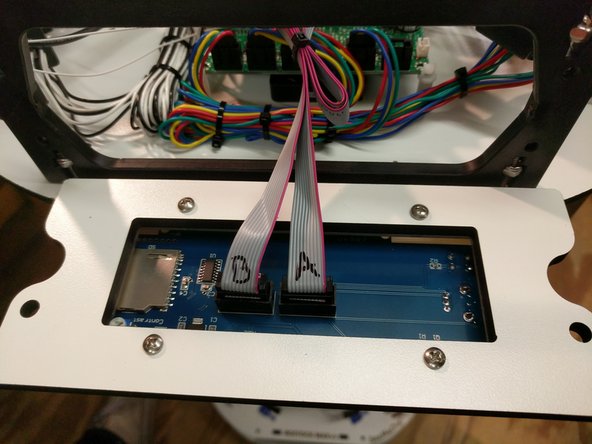
Locate and install the ribbon cables on the LCD. If they are not already labeled do so now (to match the image)
-
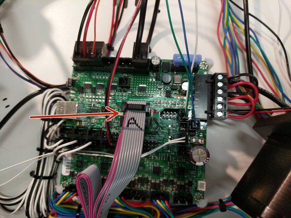
Connect the ribbon cables to the RAMBo Board in the orientation and location specified.
-
The LCD is labeled on the back EXP1 & EXP2. EXP1 = A & EXP2 = B On the LCD adapter board, the top of the adapter should be labeled by you as A and the bottom should be labeled as B
-
Note the pink stripe on the ribbon cable... this should be on the left hand side when plugged into the LCD adapter board. The connection is keyed on the LCD itself so the orientation will be correct.
-
-
-
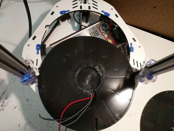
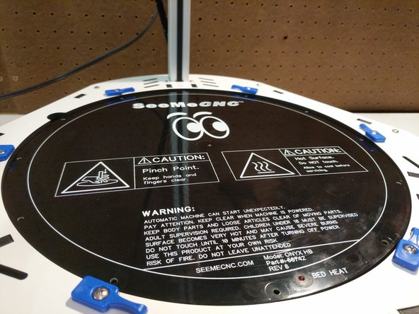
To prepare the heated bed, you must first run the 12awg black and red & (2) 26awg white wires through the bottom side (ribbed side) of the insulator. The hole for wiring is near the center of the bed.
-
Flip the bed insulator over and pull the wires through.
-
-
-
-
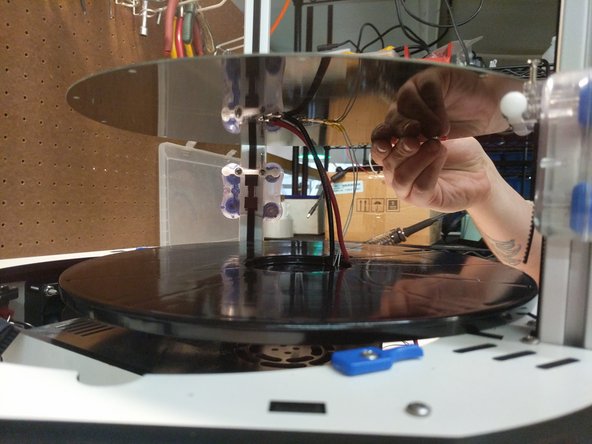
Align the heated bed with the with the bed insulator. There is a pocket for the thermistor on the insulator and there are 3 dimples (align with holes in the periphery of the heated bed) that will help you align the bed with the insulator.
-
Carefully set the insulator and bed into the base assembly of the printer.
-
The rib features on the insulator will straddle the boss features of the bed clamps (attached to the base top plate.
-
Ensure the bed can set down against the insulator. Gently pull any wires into the base if they are interfering with the bed sitting flush.
-
-
-
When handling the glass plate please do so carefully. Take extra care not to touch the top surface of the glass. Oils from your hands can prevent filament from sticking to the glass.
-
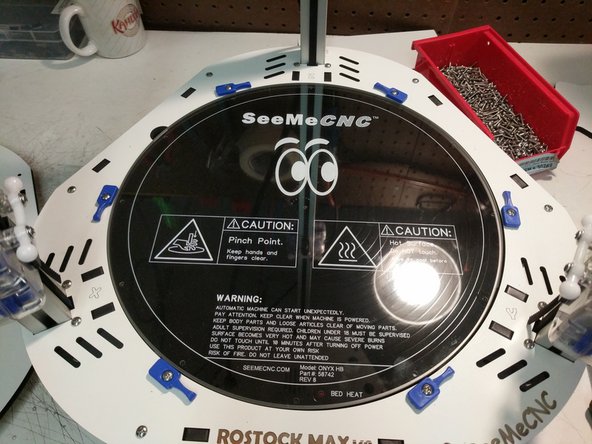
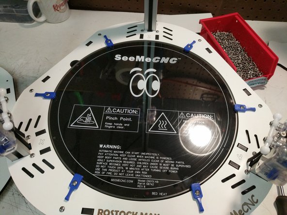
Install the glass plate on top of the heated bed.
-
Rotate the blue bed clamps so they are clamping the glass against the heated bed. Loosen/Tighten the screws as needed if required. You do not want the clamps to be so tight that they are impossible to rotate. You also don't want them so loose that the glass has the ability to move around.
-
-
-
Align the top assembly top plate with the top of the printer. Work your way around the periphery of the top plate while pressing it down onto each set of injection molded tabs. This is a process of finesse, not brute strength. When complete, the top plate should be resting flush against the injection molded parts in the area of each axis.
-
When the plate is set on all tabs you will install 6-32 x 1" screws in all 12 locations. You can fully tighten these screws.
-
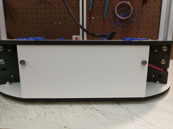
Install the top electronics cover when you have completed.
-
-
-
You can now install the remaining side covers with 10-32 socket head cap screws.
-
-
-
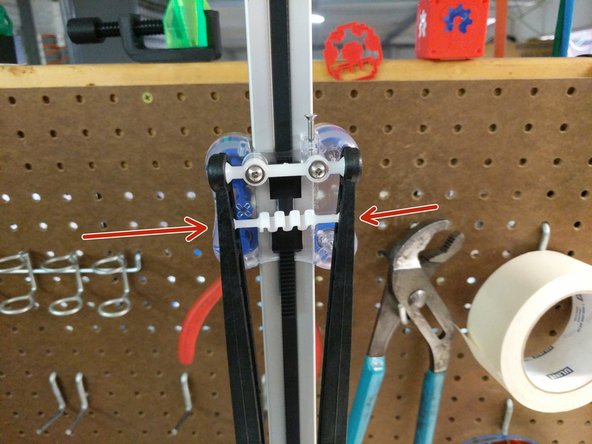
To install the arms, snap (2) ball cup arms onto a set of carriage ball joints.
-
Insert the tensioning spring between the arms in the slot.
-
Do this for all three sets of arms.
-
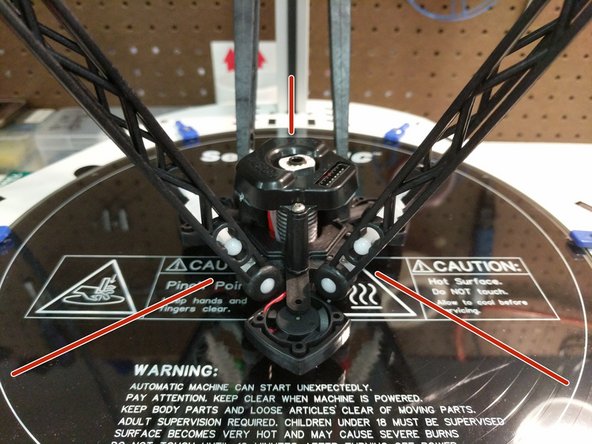
Next, you will attach the arms to the hot end. When installing the hot end: The fan in the upright position blowing across the hot end should be parallel with the Z (back) tower & The 8 pin connector should be in line with the Y axis (front right). Insert the tension spring into the arms and then snap the ball cup arms onto the ball joints.
-
Connect all three sets of arms to the hot end.
-
Ensure that you have installed the hot end in the correct orientation. Refer to the 3rd image.
-
-
-
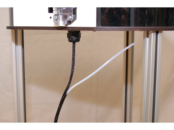
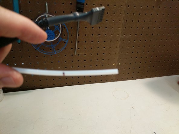
The Bowden tube is carried inside the mesh loom that holds the hot end wiring.
-
The PTFE will enter the mesh loom approximately 90mm below the extruder. Open a gap in the mesh by pressing two areas about 1" apart toward each other. This will expand the loom.
-
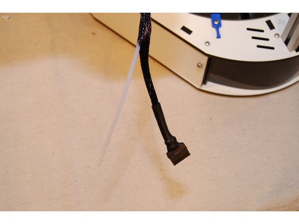
Insert the Bowden tube into this opening and thread it through the loom until it reaches a point about 225mm from the end of the hot end connector.
-
Open the loom as you did previously and thread the Bowden tube through the exit provided.
-
-
-
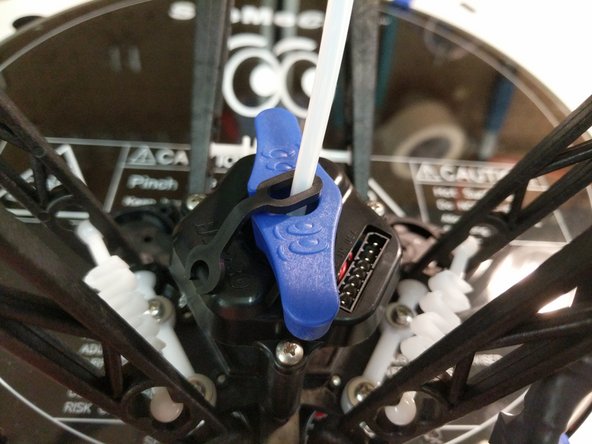
Install a retaining clip on the hot-end end of the Bowden tube and insert the Bowden tube into the hot end.
-
The Bowden tube will fit nearly the entire length of the hot end, so make sure it's fully seated. Our assembly team marks the Bowden Tube before inserting it into the hot end. The mark is placed at 46mm. When the tube is inserted it should be at or below the top of the black ring on the PTC adapter.
-
Kits shipped after 2/24 (from SeeMeCNC) will come with an HE280 PTC Tool. If you kit was shipped prior to this date, you can print your own tool (found on Repables.com) or simply use a pair of needle-nose pliers.
-
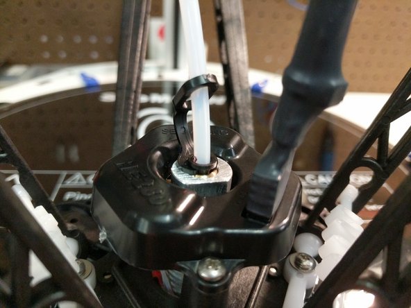
Loosen the PTC Adapter 2-1/2 Rotations. 2-1/2 rotations is a critical amount, do not loosen any more/less.
-
Rest the nozzle down against the build plate (or on a solid surface if the HE280 is removed from the machine)Seat the PTFE tube down in the hotend as far as it can go. Be sure to push hard to get it seated.
-
While maintaining downward pressure on the PTFE tube, tighten the PTC adapter slowly. Ensure that the heat sink, and heater block are not rotating while you are tightening the PTC adapter.
-
The PTC Adapter should tighten 2-1/2 full rotations (the amount you loosened it). This will cause the black ring in the top of the PTC adapter to rise up as its teeth engage the PTFE tube.
-
Insert the lanyard clip in the PTC adapter (under the black ring).
-
-
-
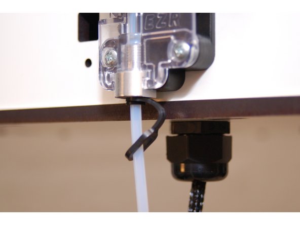
Slide a retainer clip onto the Bowden tube (Closed end)
-
Slide the Bowden tube into the EZR Struder. The Bowden tube will fit nearly the entire length of the hot end, so make sure it's fully seated.
-
Insert the locking clip between the face of the push-fit connector and it's plastic release ring.
-
After installing the retaining clip, firmly grip both the Bowden tube and push up to ensure that the tube is fully seated. The locking mechanism will allow the tube to slip in this direction.
-
-
-
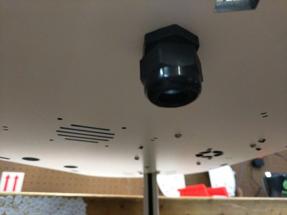
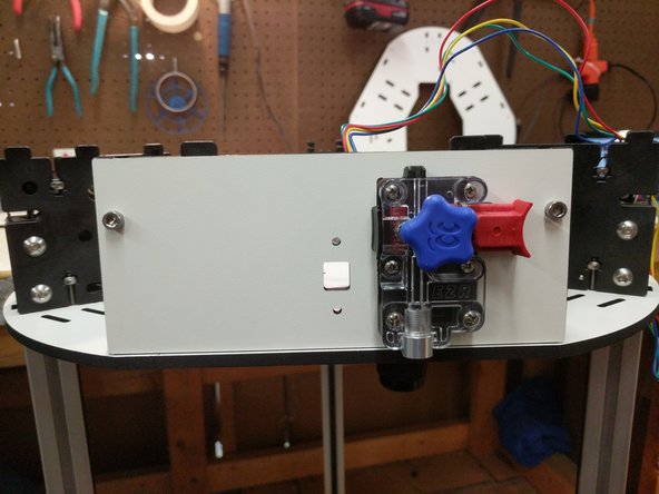
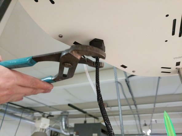
Tighten the strain relief nut on the bottom side of the top assembly
-
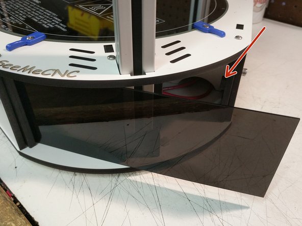
Remove the paper backing from both sides of the acrylic panels.
-
If you look at the injection molded base sides you will see the "stop" boss for the acrylic covers. Insert one side of the panel into the chosen corner, and then flex the panel into place.
-
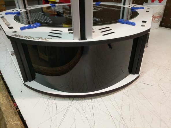
Repeat for the remaining corner covers.
-
-
-
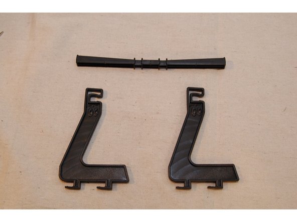
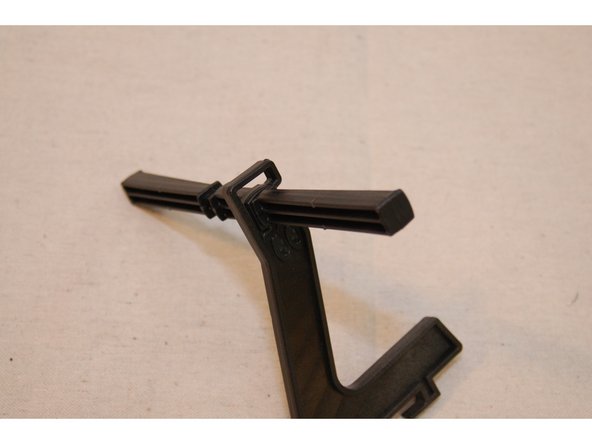
Rotate the spool support bar so that the angled face of the bar is facing away from you.
-
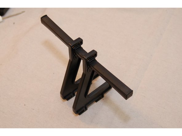
Insert the spool support into the slot in the spool support bar and then rotate the support 90 degrees on the bar. This should result in the angled face of the bar being oriented "up".
-
Install the 2nd spool support in the same fashion.
-
-
-
-
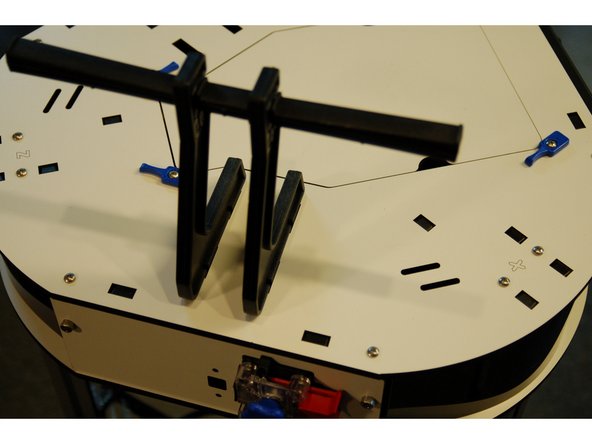
You can use the back of a screwdriver or a light rubber mallet to slide the Spool Holder into it's fully-installed location.
-
-
-
The printer is now built, congrats!
-
Next you will proceed to installing firmware and performing calibrations on the printer.
-
Proceed to: Installing the Firmware
-


Cancel: I did not complete this guide.
14 other people completed this guide.
