
Introduction
Before you begin
Please read this and all steps thoroughly before proceeding with your build. SeeMeCNC has gone through extensive research, testing, and manufacturing of the highest quality workmanship in this field. Close tolerances and fitment are necessary to ensure the accuracy customers expect. Be extra careful when handling edges such as on the tower assemblies. Mishandling or misalignment can cause damage to wires that may be installed or routed improperly. Use caution when handling precision machined parts.
-
-
First, click here to read safety information . This safety information may be updated at anytime so occasionally check for updates.
-
NOTE: This guide is intended to be followed online in order to fully utilize the links and documentation found within.
-
-
-
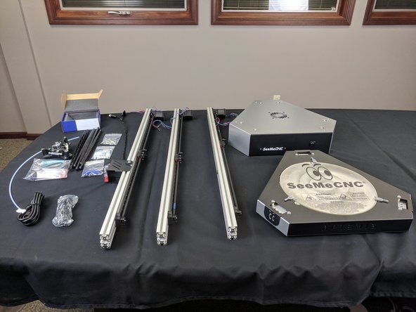
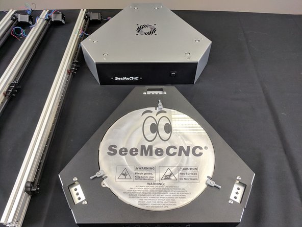
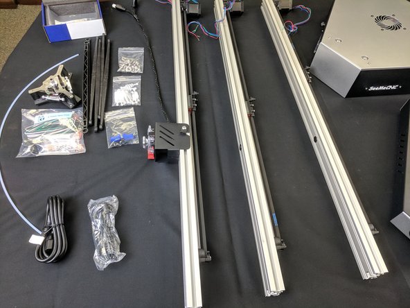
Inside the large box that the Artemis 300 comes in, are the rails, and two medium sized boxes. Carefully remove the rails and set them aside.
-
Remove the two medium sized boxes and CAREFULLY cut the packing tape.
-
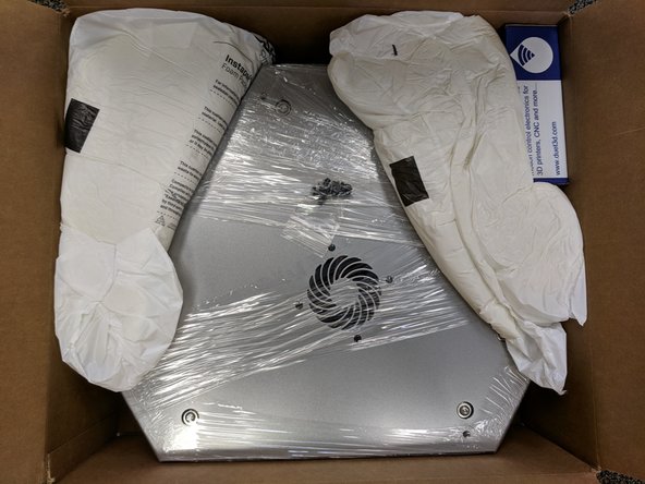
The pictures in this step show the base assembly. There is yet another box within this box. This smaller box has all the accessories and parts for assembly.
-
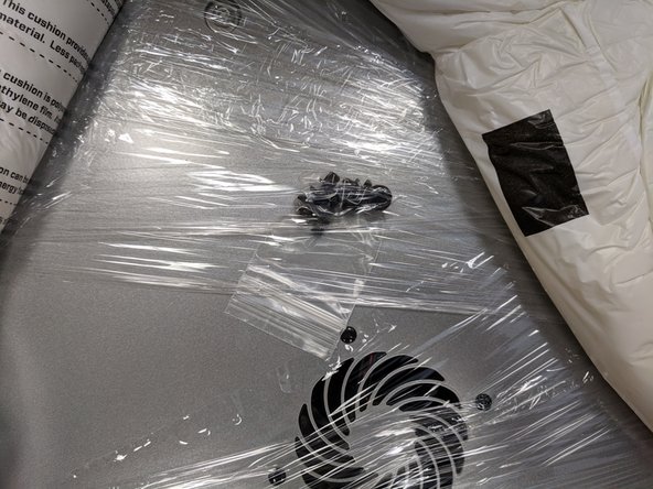
You can carefully remove the shrink wrap from the base assembly. NOTE: There is a small package of press in rivets shrink wrapped to the base assembly. DO NOT LOSE THESE!
-
-
-
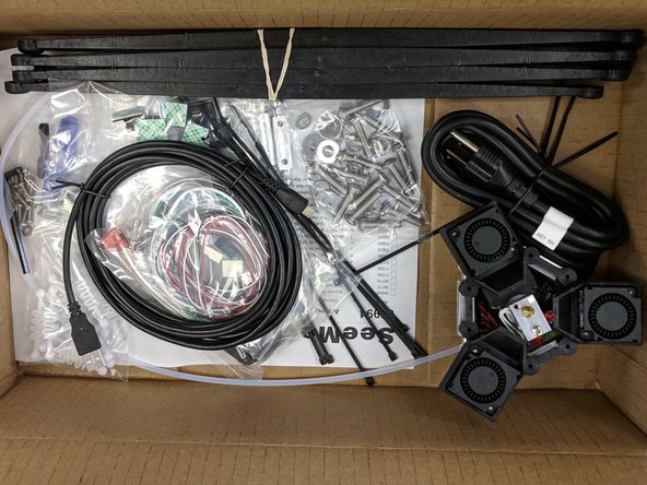
The smaller box in the base assembly pack is the accessory / assembly contents.
-
-
-
The other medium box is the upper assembly.
-
You can carefully remove the shrink wrap from the upper assembly. NOTE: There is a small package of press in rivets shrink wrapped to the top assembly. DO NOT LOSE THESE!
-
One final item in this box is the DUET box. This box contains connectors and crimps. Do not discard this box!
-
-
-
There are 3 towers for the Artemis. 1 of the towers has the extruder and hot end whip pre-installed. For this step you can choose either of the remaining 2 towers to be the Z tower.
-
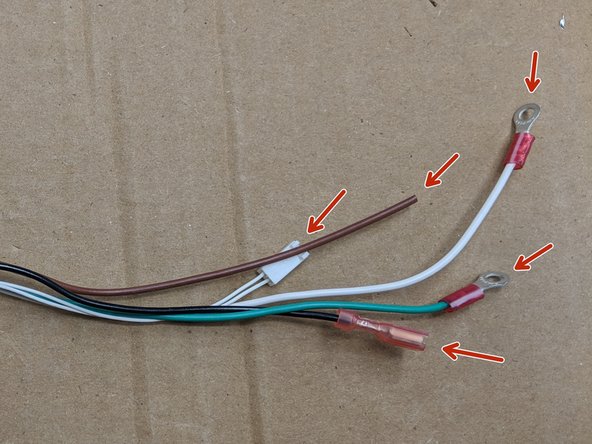
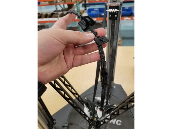
Locate the Z Tower Wire pack. Remove the wires from the pack and straighten them out. Be careful not to lose any of the connectors from the pack.
-
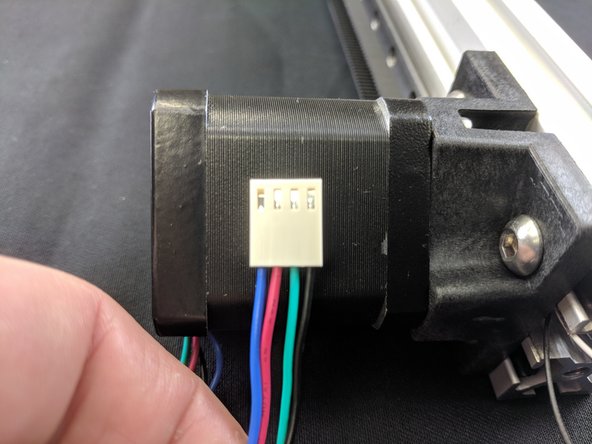
The connectors shown will be in the top of the machine (the side with the stepper motors).
-
Please make sure you have the wires in the orientation shown.
-
-
-
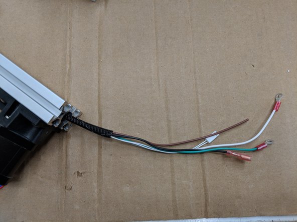
The first set of wires to feed in the Z Tower are the 18awg wires. These are the thicker wires from the Z Tower Wire Pack. Please ensure to have them oriented the correct way.
-
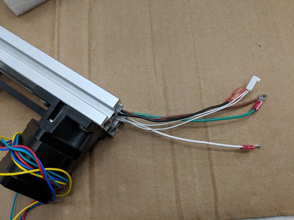
You will feed from the bottom of the tower (opposite the stepper motor). Feed the following: 18awg white and green wire with ring terminal, 18awg black wire with straight spade terminal, 18awg wire with NO terminal.
-
These wires can be fed by pushing small bits at a time. If you feel resistance, back the wires out about 25mm and then try pushing forward again.
-
Ensure you get the same number of wires exiting the end the end of the tower that you started feeding.
-
Now run the remaining wires. This is easiest using a piece of filament to pull wire.
-
Run the included mesh loom over the wires and secure with a zip tie. This is to secure the wires for later steps.
-
-
-
THIS IS AN INFORMATIONAL STEP FOR FUTURE PROCEDURES. NO ACTION IS NEEDED FOR THIS STEP.
-
-
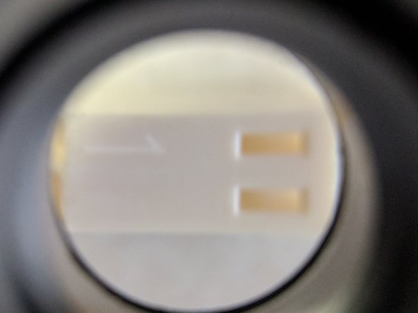
Make sure that the contact locks into the connector shell. The contact has a small metal tab. The tab will pop up into the slot on the face of the connector shell, locking the contact in place.
-
-
-
THIS IS AN INFORMATIONAL STEP FOR FUTURE PROCEDURES. NO ACTION IS NEEDED FOR THIS STEP.
-
The KK connectors have a #1 molded into them for pin identification. This is very difficult to see if you are not looking for it.
-
-
-
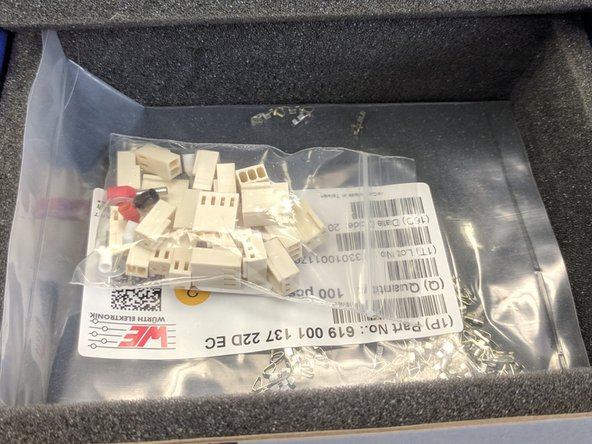
There are two different connectors. The off-white connectors in the DUET controller box are slightly different than the KK Molex (bright white) connectors SeeMeCNC installs on the wires. If you need to replace any terminals using the DUET supplied connectors, replace the enter end of the motor or switch. The crimp terminals are NOT interchangeable.
-
IF THESE KK CONNECTORS ARE NOT WITH THE Z TOWER WIRE PACK, THEY WILL BE LOCATED IN THE DUET BOX SUPPLIED WITH YOUR PRINTER KIT.
-
-
-
Current machines will have the motor connectors already installed. Newest machines will have Red, Green, Yellow, and Blue wires instead of what is shown. If this is the case, ignore this step.
-
Machines AFTER 3/20/2018: Motors can have a black connector and different color wiring, They are connected with the smooth side of the plug towards the edge of the Duet.
-
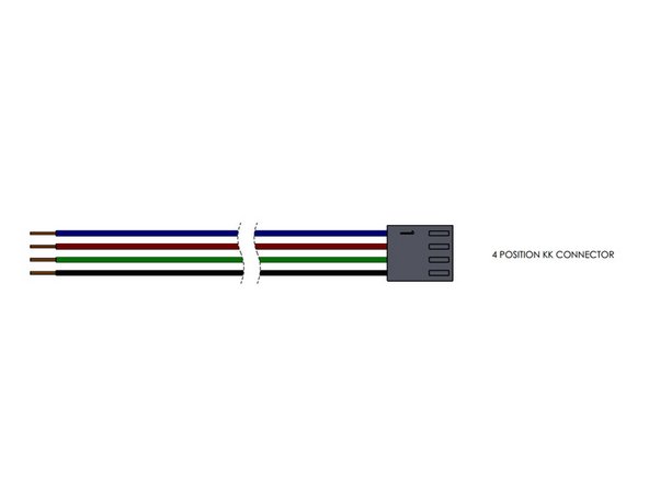
The wires of the motion stepper motors will install into Molex KK 4 pin connectors. These wires will install into the connectors similarly to how previous wires were installed into the KK connectors.
-
PIN 1 is indicated with a "1" on the connector. It is difficult to see if you are not looking at it closely, but it is there.
-
Blue wire: Pin 1
-
Red wire: Pin 2
-
Green wire: Pin 3
-
Black wire: Pin 4
-
-
-
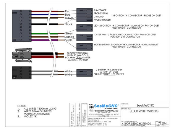
Please reference the wiring diagram in the image or click this link for the old version of wiring diagram if you have 2 orange wires: Whip Wiring.
-
LED: Green Wire - 2 pin KK connector - PIN 2
-
HE FAN: Orange Wire or Purple Wire - 2 pin KK connector - PIN 2 Wire color change is explained in Step 27.
-
LAYER FAN: Orange Wire - 2 pin KK connector - PIN 2
-
PROBE: Red PIN 1, Blue PIN 2, Black PIN 3, Brown Wire PIN 4 - 4 pin KK connector
-
E0 TEMP: 2 White Wires - 2 pin KK connector - PINS 1 & 2 (Polarity DOES NOT matter)
-
-
-
We will now begin to prepare the top of the machine to install the towers.
-
There is a fan installed on the cover. Current machines have this connector already installed. If not, it will need a connector installed on the leads. You will use a 2 pin KK connector. Install the red wire in PIN 1 and the black wire in PIN 2.
-
You can now set the cover aside.
-
-
-
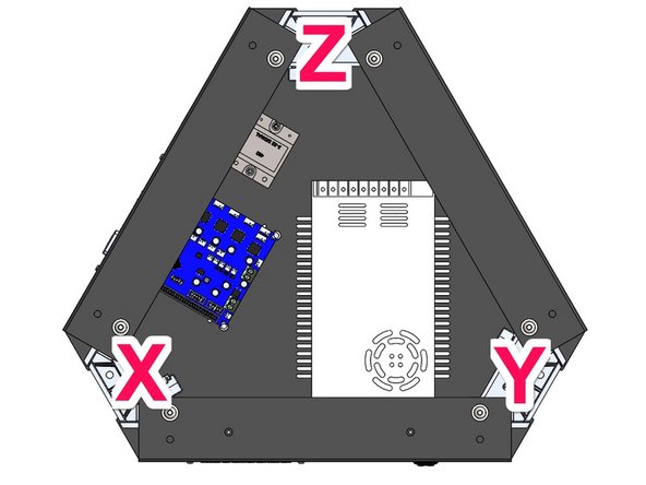
This image of the Upper Assembly will assist you in identifying the X Y & Z tower locations for correct installation.
-
-
-
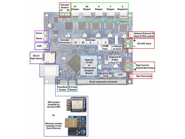
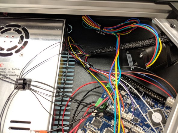
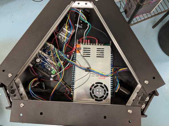
This image is an overview of the Duet Wifi wire connection locations. You can reference it as needed.
-
You can download it as a PDF HERE
-
-
-
The X Tower will be the first tower to be installed. This tower is the one with the extruder and whip pre-installed. To begin, you will want to elevate the printer's upper assembly so it is up higher than the length of the rail. For our assembly we used the box that the upper assembly came in, or a workbench height table.
-
If you have not done so at this point, you'll want to make sure you remove the 1/4-20 x 1" long button head screws, split ring washer, and flat washer from the end of the tower for the following steps. The same goes for all other towers as you get to them.
-
Ensure that the end-stop legs are bent over at a 45 degree angle as shown in the picture. Check at all 3 tower locations in the upper assembly.
-
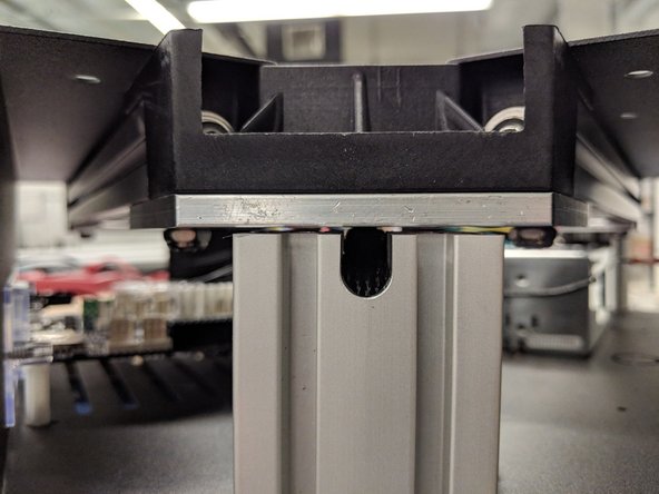
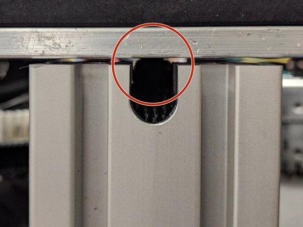
You will want to grasp all the wires that are exiting the top of the X tower and push the bundle down in the relief that is cut into the T-Slot. Pushing down on the wires will help create a little memory in the wiring.
-
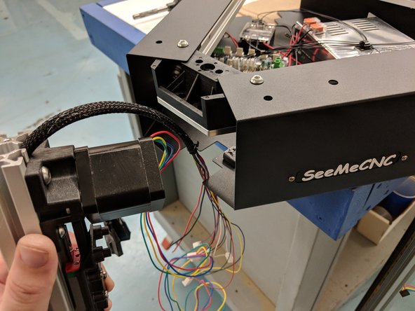
You will now want to feed the bundle of wires in through the opening in the side of the sheet metal enclosure.
-
Continued on next step...
-
-
-
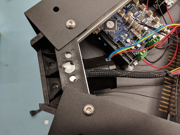
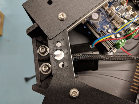
You will now lift the tower and slowly slide it into the upper assembly. The tower assembly will clear the limit switch. As you are sliding it into place you will need to ensure that the wires stay down in their relief, otherwise they will get pinched when tightening the plate.
-
Make sure to look from the outside of the tower towards the center of the upper assembly and ensure that the wires are ALL in their relief.
-
Secure the tower in place by reinstalling the 1/4-20 x 1" long button head screws, split ring washer, and flat washer stacked the same as you removed them.
-
-
-
You will now install the Z tower, similarly to how you installed the X tower. The Z tower is the one in which you previously ran wires down. Start by making sure the end-stop legs are folded over.
-
Begin by measuring the length of the wires that exit the Z tower. You will want to have 1 foot of wire exiting the tower at the bottom. Make the adjustment of the wires now.
-
As you did before, grasp all the wires at the top of the tower (the end with the stepper motor) fold them into the relief in the T-Slot and hold to give them some memory.
-
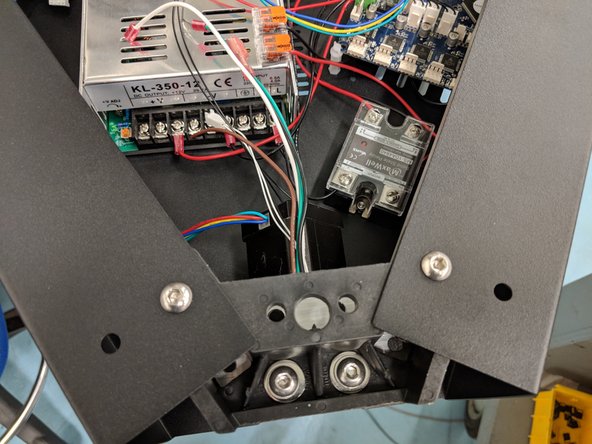
Feed the wires into the opening in the side of the upper assembly. This is the opening that is the opposite of the name badge (front of the printer).
-
Slide the tower into the opening as you did with the X tower.
-
Make sure to look from the outside of the tower towards the center of the upper assembly and ensure that the wires are ALL in their relief.
-
Attach the tower to the upper assembly using 2 each of the provided 1/4-20 x 1" long button head screws, split ring washer, and flat washer. Fully Tighten.
-
-
-
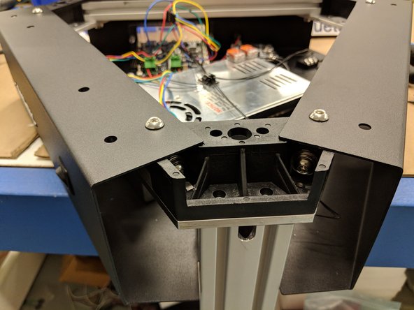
Install the final tower. This is the Y tower. It will install the same as the previous two towers, with the exception that this tower has no wires installed so you will not have to worry about pinching any wires.
-
After you have installed this tower, tighten fully.
-
All towers have now been installed.
-
-
-
THIS IS AN INFORMATIONAL STEP FOR FUTURE PROCEDUREs. NO ACTION IS NEEDED FOR THIS STEP.
-
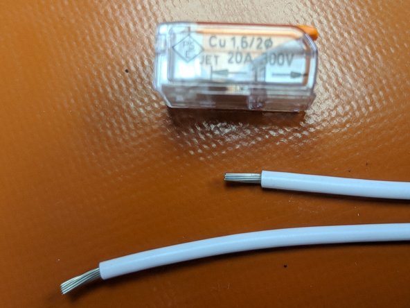
There is a wire strip length gauge on the side of the Wago connector. When you use this connector, make sure that the ends of the wire that are going to be in the Wago are stripped the appropriate length.
-
11mm is the correct wire strip length.
-
-
-
The red and black 18awg wires from the X tower DO NOT have connectors. These are for the E0 Heat.
-
You will install these wires in the Wago Connectors that are attached to the top of the power supply.
-
Black to Black & Red to Red.
-
If you are having trouble getting these wires to reach you may need to get feed some of the whip back into the tower (in the hole in the side of the X Tower) to provide enough length for these wires.
-
Lift up on the orange lever on the Wago connector without a wire in it and insert the wire all the way until it stops. Then flip the lever down. This will secure the wire. Repeat for the other wire.
-
You may need to strip a little extra of the sheathing off to make sure that the Wago connector is properly clamping down on the metal of the wire.
-
-
-
The hotend probe connector (4-pin red, blue, black, brown wires, exiting the X tower wire bundle) is keyed and will only connect in one direction in the location indicated in the photo.
-
-
-
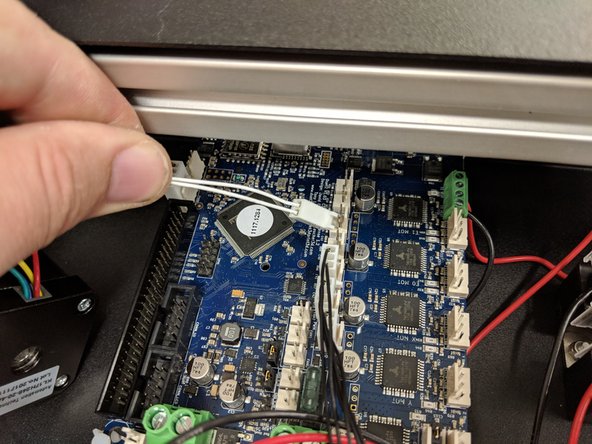
The hotend thermistor connector (2-pin 2 white wires, exiting the X tower wire bundle) is keyed and will only connect in one direction in the location indicated in the photo.
-
-
-
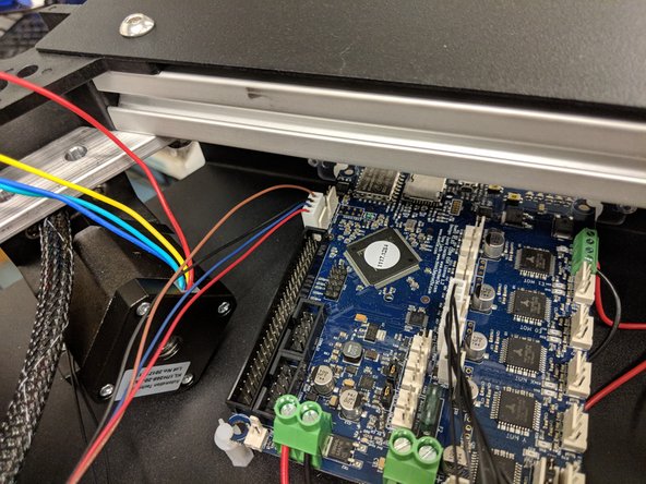
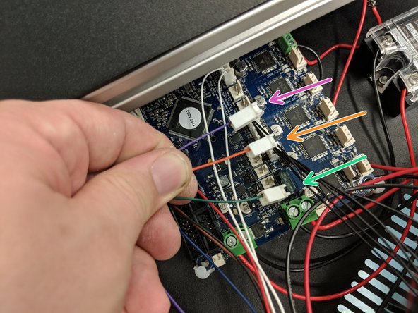
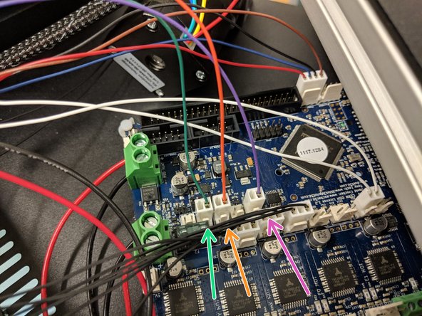
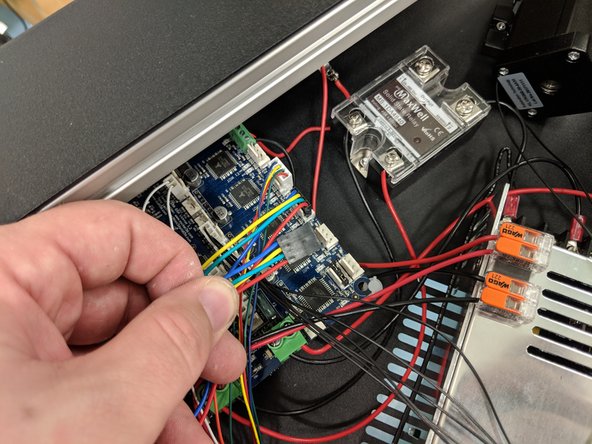
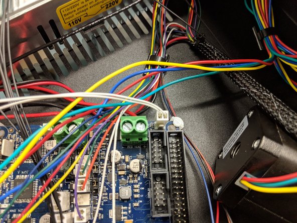
The green, orange, and purple wires exiting the X tower bundle connect to the locations shown in the photos.
-
-
-
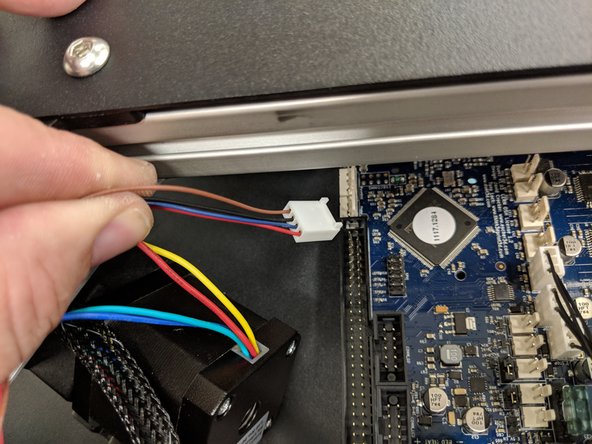
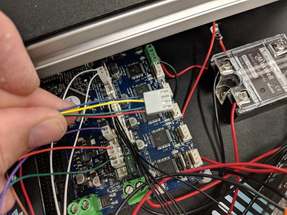
The extruder motor connector (4-pin red, green, yellow, blue wires, exiting the X tower wire bundle) is keyed and will only connect in one direction in the "E0" location indicated in the photo.
-
Newer machines will not have a white connector as shown in the photo. They will have the same black 4-pin connector as the other motors, and will install the same way those do but in the "E0" position.
-
-
-
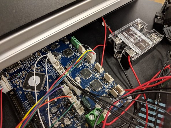
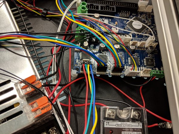
The X tower motor connector (black 4-pin red, green, yellow, blue wires) will install in the X stepper position on the board.
-
Plug the connector in so that the smooth flat side of the black connector is facing the outer edge of the Duet.
-
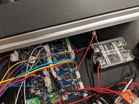
Clean up the excess wire with a zip tie. Make sure the wires aren't near where the fan from the top silver cover of the top assembly will end up, you don't want the wires getting stuck in the fan later.
-
-
-
Repeat previous steps with the remaining two tower's wires. Use the diagram to make sure you're plugging them in to the correct positions.
-
-
-
The bed thermistor connector (2-pin with 2 white wires, exiting the Z tower wire bundle) is keyed and will only plug in one direction in the location shown in the photo.
-
-
-
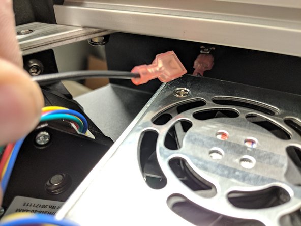
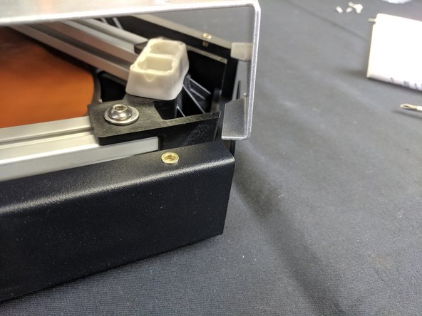
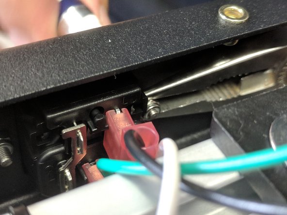
The power switch connector (black wire with spade crimp, exiting the Z tower wire bundle) connects to the free tab on the power switch as shown.
-
-
-
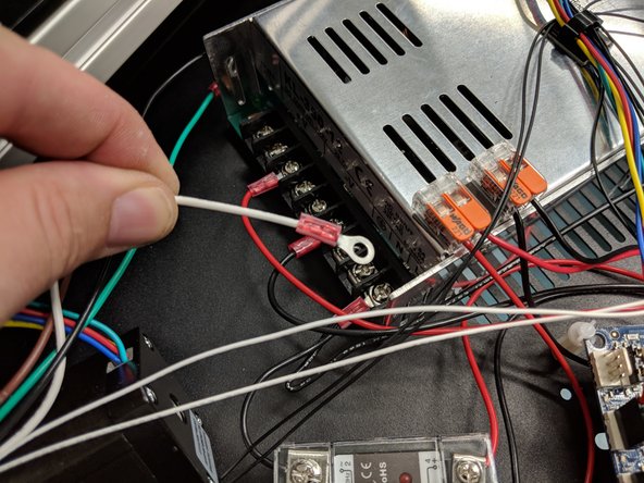
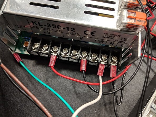
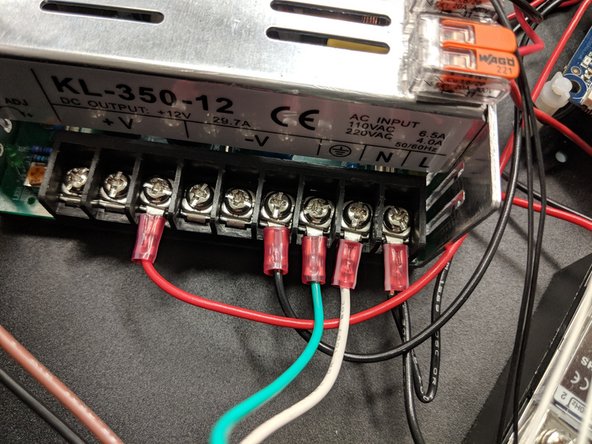
The ground (green) and neutral (white) wires go to their respective locations on the power supply. Unscrew the clamps and reinstall with the ring terminals in place as shown.
-
-
-
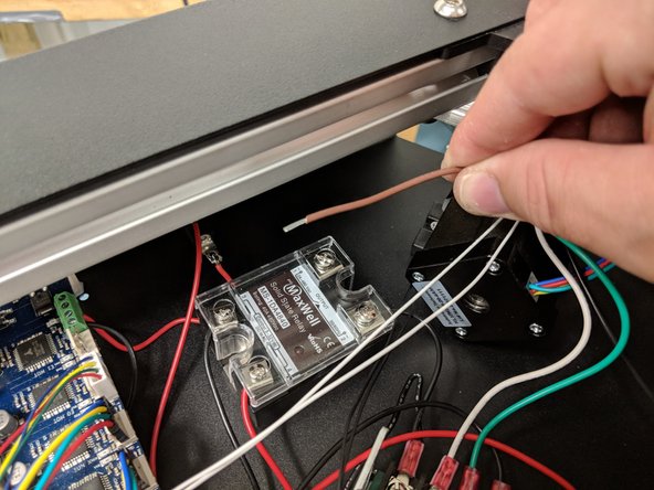
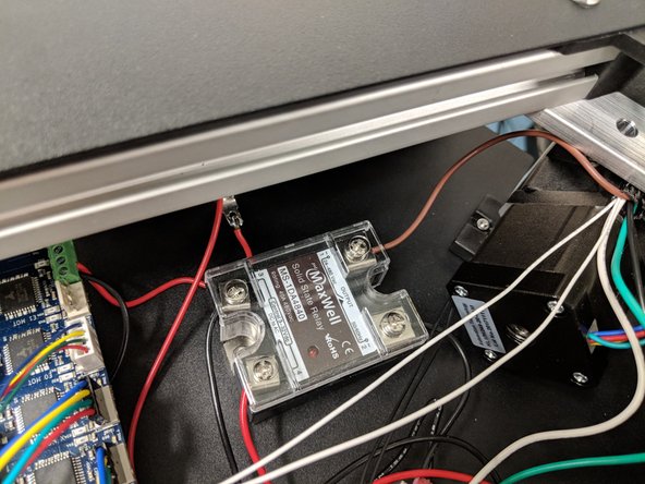
The brown wire exiting the Z tower with NO connector on it will install in the only empty clamp on the relay.
-
You may need to strip a little extra of the sheathing off this wire.
-
Unscrew the clamp on the relay just enough to insert the wire.
-
Insert the wire as close to the center of the clamp where the screw is as possible, then tighten the screw to clamp the metal plate down on the wire.
-
Make sure not to tighten the screw too much!
-
You're now done with the top wire connections!
-
-
-
Carefully flip the machine upside down and set it on the ground on something like cardboard so at not to damage the machine.
-
The picture doesn't show cardboard under the machine because we at SeeMeCNC like to live on the edge. A surface that won't scratch the machine is really recommended here.
-
-
-
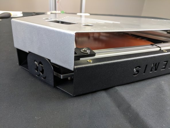
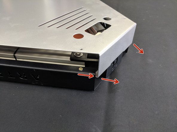
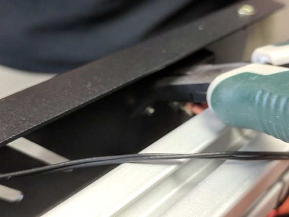
To remove the cover, lift it straight up on all three corners. You will then need to gently pull out on the silver sides (one corner at a time) to un-hook the cover.
-
-
-
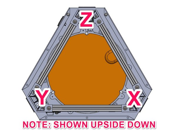
This image of the Lower Assembly will assist you in identifying the X Y & Z tower locations for correct installation.
-
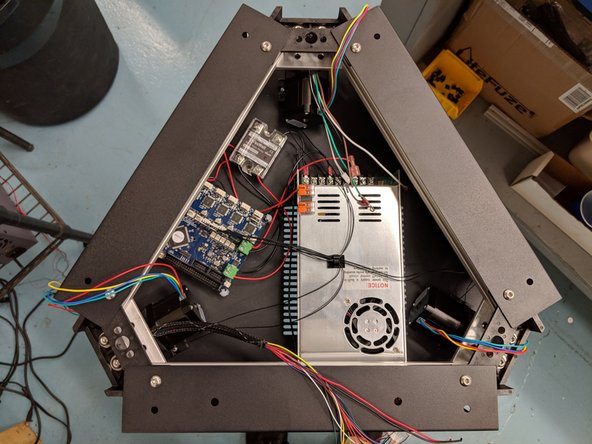
This image shows the base assembly upside down, as it would appear when preparing for installation.
-
-
-
Route the Z tower wires through the opening in the Z tower location on the bottom assembly.
-
Make sure all wires are in the channel without pinching, as you did when installing the top wires.
-
-
-
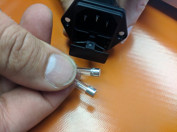
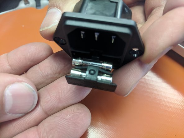
Open the fuse drawer on the IEC connector. Insert the two fuses that were provided into the location. as seen in the image. Close the drawer.
-
-
-
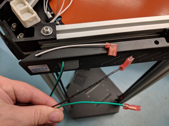
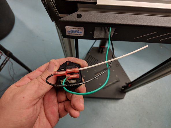
Locate the black and green wires with crimped connectors exiting the Z tower shown. Also locate the short white wire with crimped connector from your Z tower wire pack.
-
Install them as shown on the IEC connector.
-
-
-
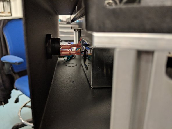
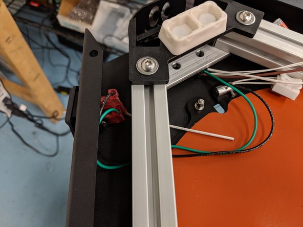
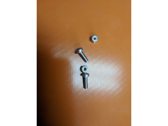
You will secure the IEC Connector to the sheet metal with M3 x 10mm screws and nylon lock nuts.
-
These nuts are hard to get to. It is easiest to hold them with a pair of needle nose pliers, and even better if you have angled needle-nose pliers.
-
-
-
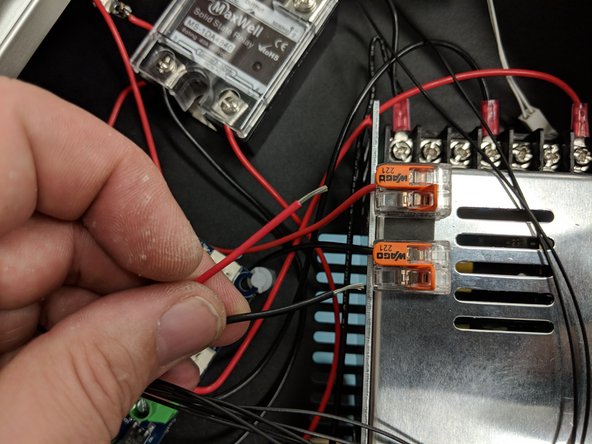
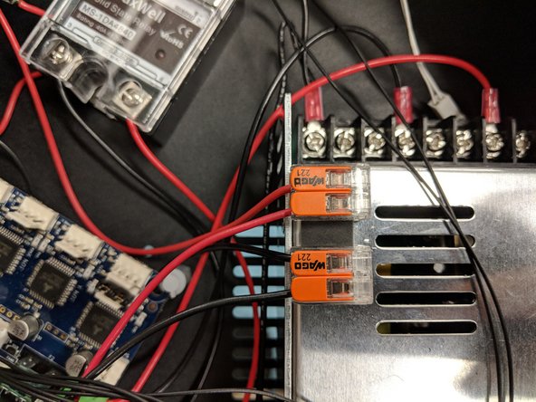
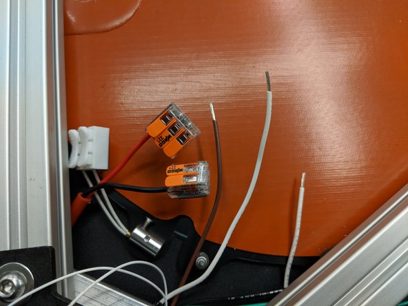
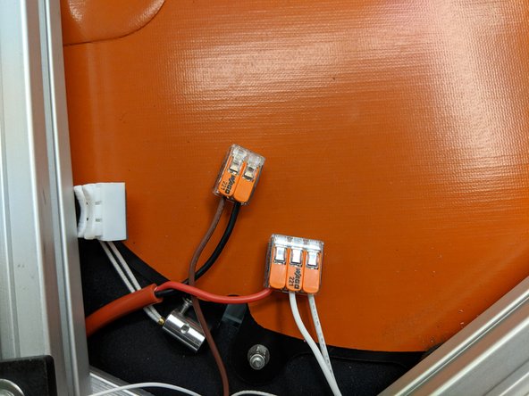
Locate the two white and one brown wires that at exiting the Z tower in the bottom assembly.
-
Install the two white wires in the open positions on the Wago connector with the red wire.
-
Install the brown wire in the open position on the Wago connector with the black wire.
-
-
-
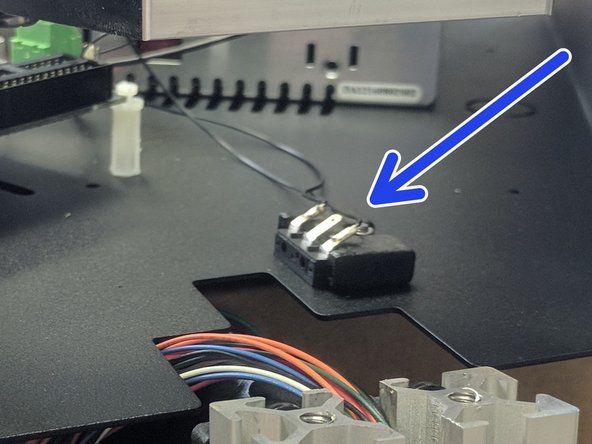
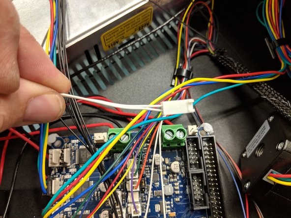
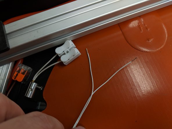
Your final two white 26awg wires exiting the Z tower in the bottom assembly will connect to the white toggle connector as shown.
-
Make sure the connection is solid in this white connector. If they slip out, you will have to remove the bottom cover later to troubleshoot thermistor issues!
-
-
-
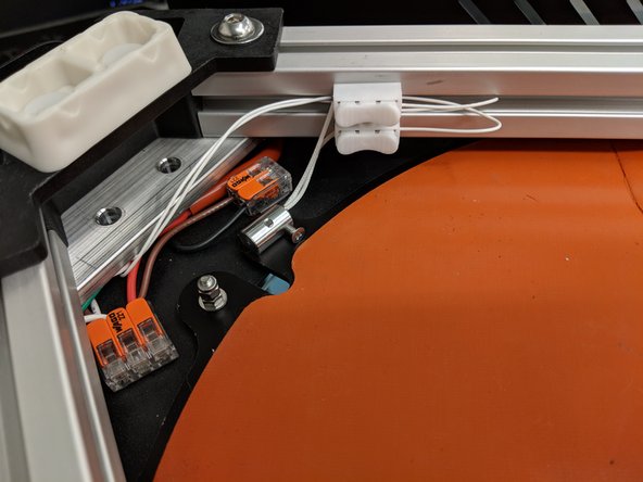
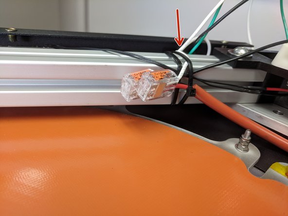
Add a wire clamp to the aluminum plate and secure the loose wires.
-
Secure the wires / Wago connectors to the T-Slot with a zip tie.
-
-
-
The base of the machine is complete, but before installing the base cover, we want to proceed with rest of assembly. After all functions are confirmed to be working we will revisit installing the base cover.
-
Carefully flip the machine over so it is right-side up.
-
-
-
Flip the printer back over and put it on a work surface. Team lifting may be required, as the printer is heavy.
-
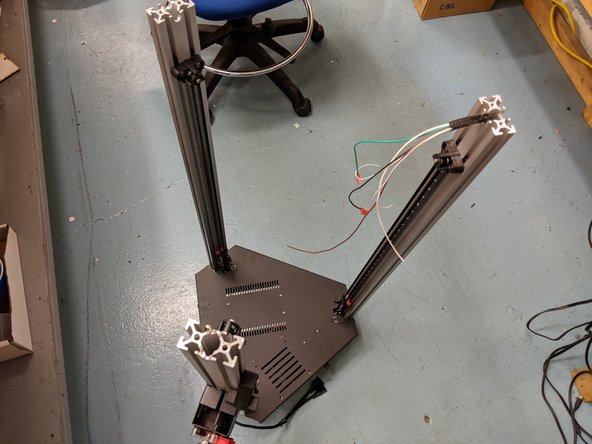
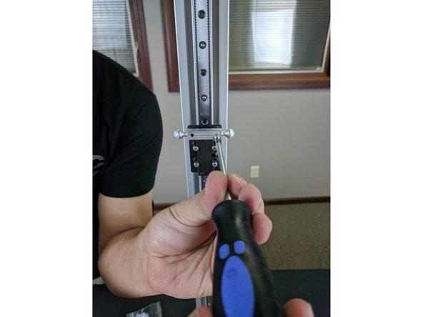
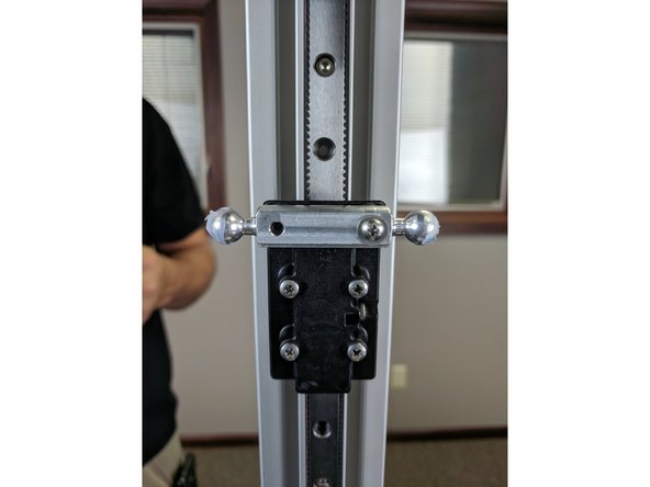
Locate and install the metal ball joints. Each ball joint is installed onto the carriage with (2) 1/2" long #4 sheet metal screws and #4 washer.
-
Complete this operation for all 3 towers.
-
-
-
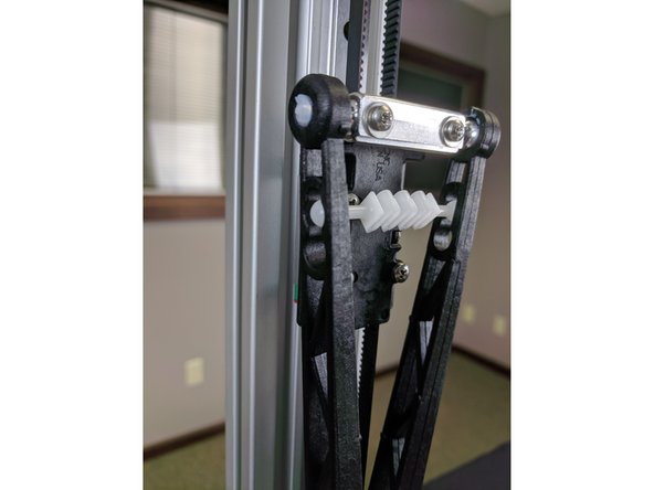
Before installing the arms, apply the provided lubricant to the ball joints. Use a q-tip, finger, or similar item to apply a small amount of lubricant to each aluminum ball joint on the carriage and on the hot end (6 total ball joints)
-
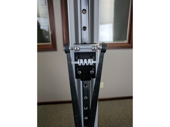
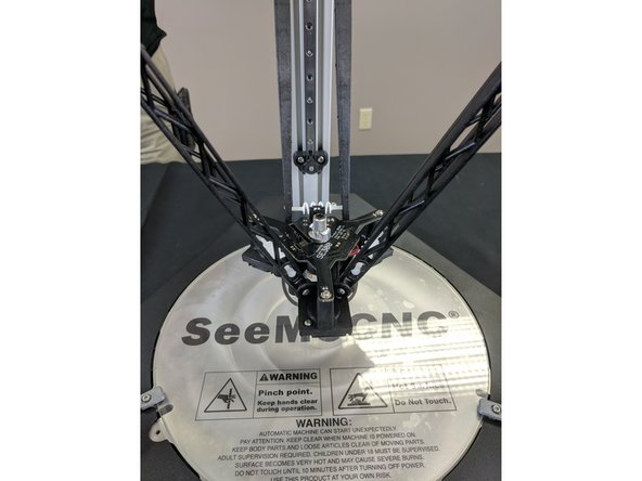
Next install the arms to the ball joints. Press the arms onto the ball joints until you hear it pop/click. It is easiest to install both arms to the carriage and then insert the tension spring between the arms. Complete all 3 carriages before moving on. Let the arms dangle.
-
-
-
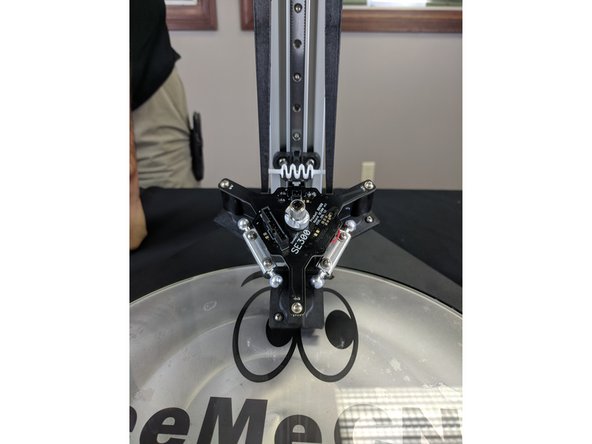
Install the hot end in the orientation shown in the images.
-
The easiest way to install the arms is to attach one arm to one of the ball joints, then insert the tension spring between the two arms.
-
Slowly stretch the second arm over and onto the other side of the ball joint until you feel or hear it "pop" onto the ball joint.
-
Extra tension springs have been provided in case one breaks while you are assembling.
-
-
-
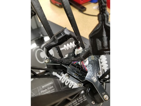
Pull back the cable boots to give access to the connectors at the end of the whip.
-
Plug in the 10 pin SL connector to its home on the hotend.
-
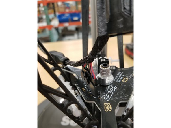
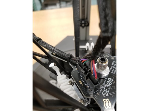
Rout the power and thermistor section of the whip to the back left of the hotend and zip tie around the mesh loom and the hotend board arm as shown.
-
-
-
Plug in the 4 pin SL connector and the 2 pin phoenix connector to their homes on the hotend board.
-
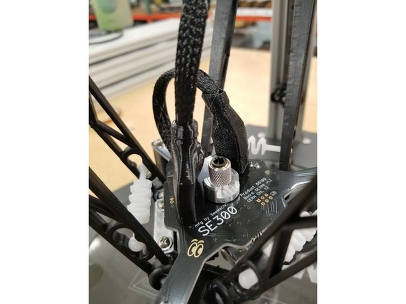
Slide the boots in to place, routing the whip extension through the opening in the back of the 10 pin boot as shown.
-
-
-
The Bowden Tube is the clear tube that delivers the filament from the extruder (EZR Struder) to the hot end (SE300).
-
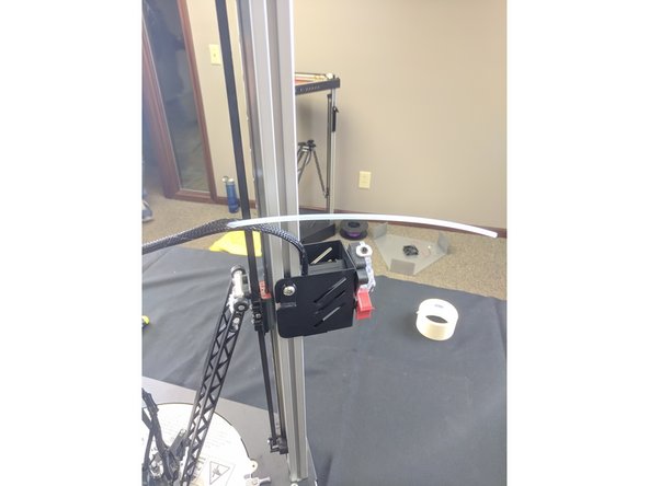
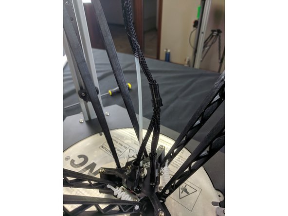
Bunch the mesh loom up approximately 100mm from the top of the extruder and insert the Bowden Tube.
-
Push the Bowden Tube through the whip until you feel it 25-50mm from the "Y" in the whip.
-
Bunch the mesh loom up near where you feel the Bowden Tube and push the tube out through the loom.
-
Contrary to the second photo, do not insert the Bowden Tube into the hot end yet.
-
-
-
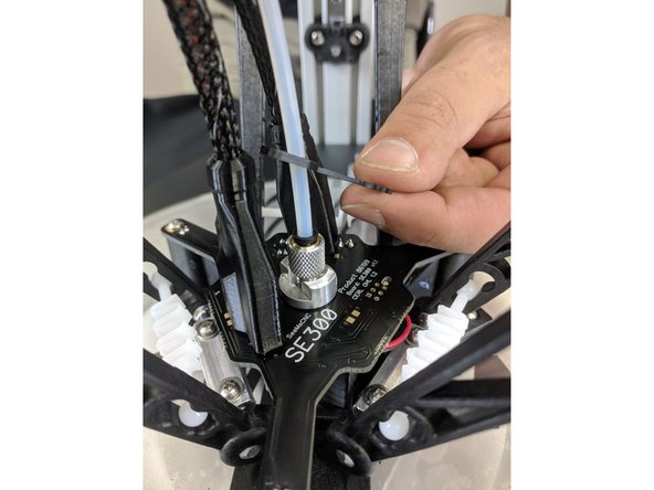
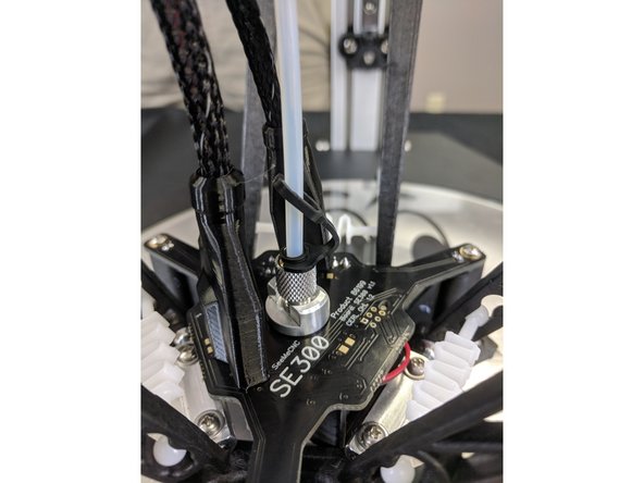
Slide a PTC clip onto the Bowden tube as shown.
-
Insert the Bowden Tube into the top of the hot end.
-
Lift up on the black ring in the top of the hot end and slide the PTC clip into the groove between the black ring and the aluminum adapter.
-
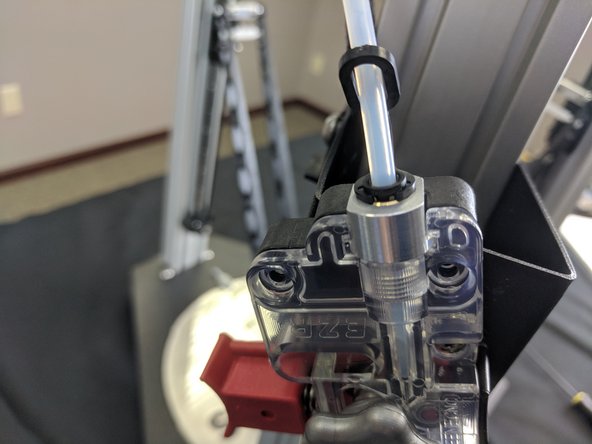
Perform the same operation on the EZR Struder side. NOTE: approximately 45mm of Bowden Tube will insert into the EZR Struder.
-
-
-
At this time we will wait to install the two covers. We will perform the initial power up and check functions before buttoning up. For the sake of continuity though, we have included the installation of the covers in this guide. So, read about it now so you can install it later, or came back later for the correct installation procedure.
-
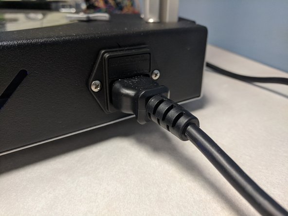
Plug in the power cable to printer.
-
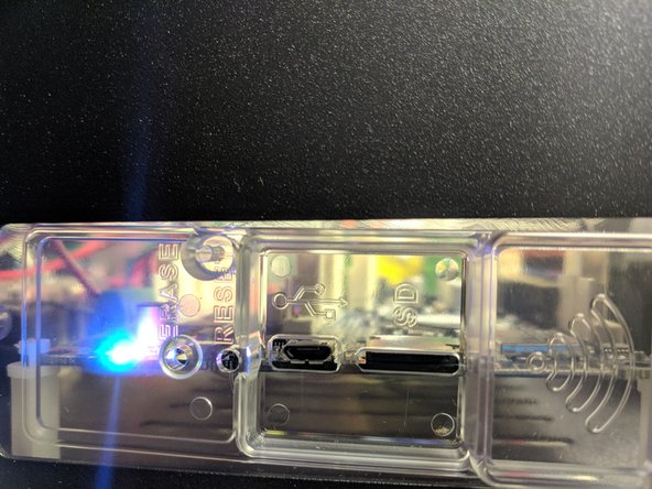
Turn the printer on.
-
The hot end should light up, as well as the status LEDs on the Duet board.
-
We will now move on to the initial connection and setup. NOTE: We will install the base & top cover when complete.
-
Go Here Next > Configuring Artemis
-
-
-
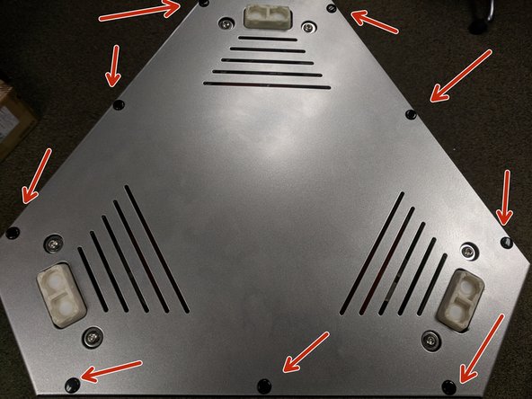
You will now re-install the base cover. Before doing so, make sure all wires are secured and not going to interfere with its installation. If you find a loose wire, use a zip tie to secure it to a piece of T-Slot.
-
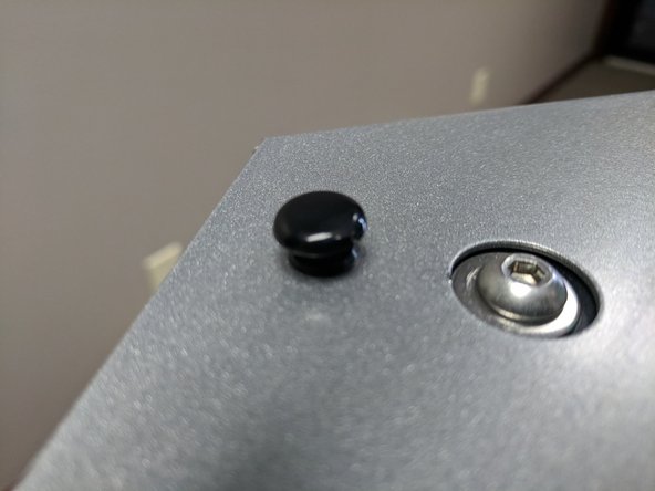
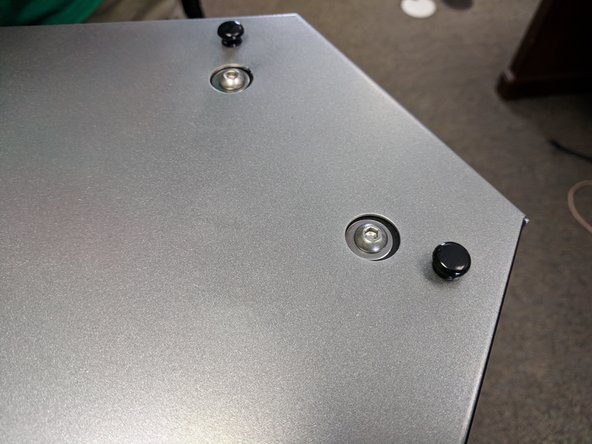
Most Artemis 300s were shipped with Removable Plastic Rivets. These easily press in and secure the sheet metal enclosure (and are easily removable for future needs)
-
Remember, if your sheet metal enclosure is secured with screws, DO NOT use power tools to tighten the cover screws!
-
-
-
Most Artemis 300s were shipped with Removable Plastic Rivets. These easily press in and secure the sheet metal enclosure (and are easily removable for future needs)
-
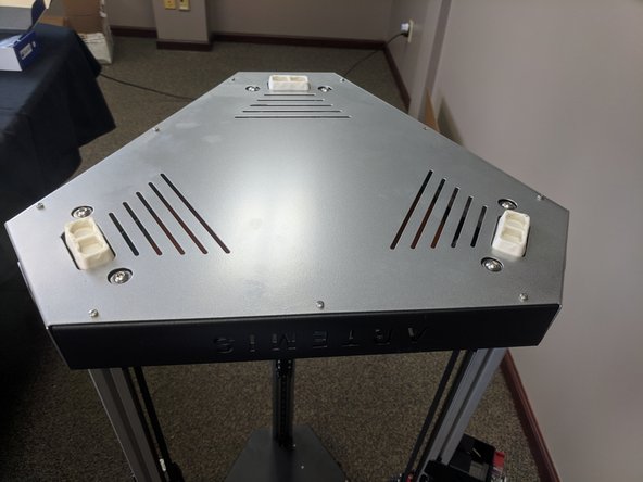
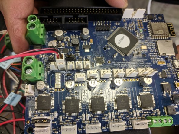
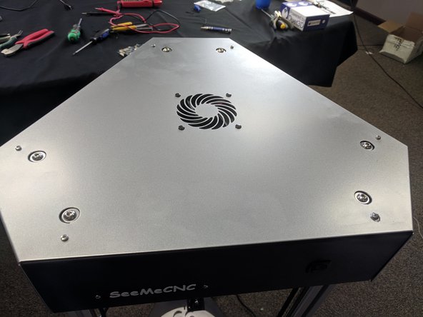
The top cover has a fan installed. This fan should be plugged into an ALWAYS ON FAN terminal on the DUET board. This is highlighted in the photo.
-
After you have plugged in the fan, slide the cover down onto the top of the printer and secure with the 6 removable plastic rivets or tighten the 6 screws. Remember, NO POWER TOOLS!
-


Cancel: I did not complete this guide.
One other person completed this guide.
Attached Documents
