
-
-
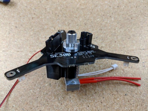
This guide will show you how to assemble the SE300 hot end and effector platform.
-
The micro controller probe circuit is 3.3VDC and is not compatible with RAMBo boards.
-
-
-
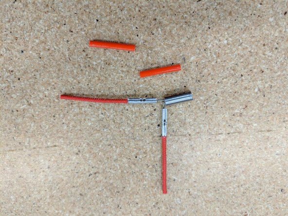
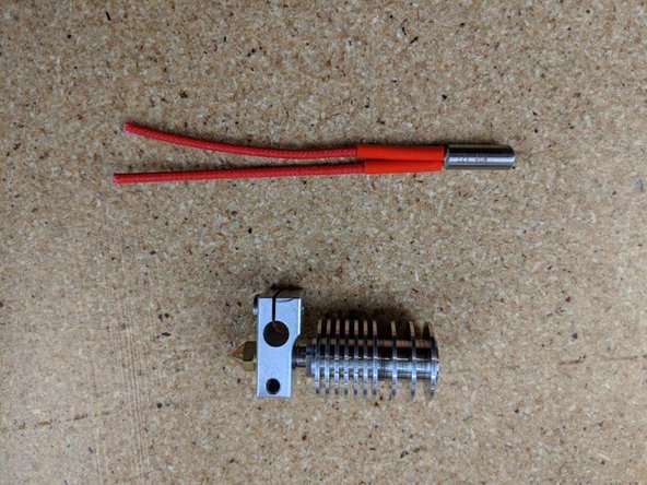
Start with the heating cartridge and remove the two tubes covering the legs of the heating cartridge. *Note: some cartridges will not have these tubes, that is normal.
-
Cut the legs of the heating cartridge to 11 mm.
-
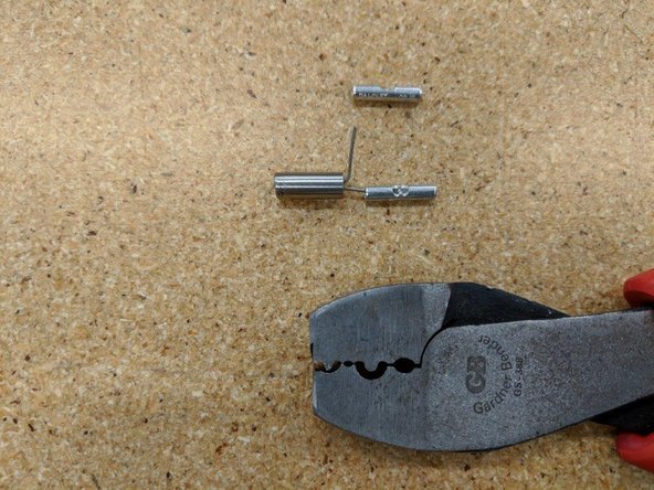
Bend one leg of the cartridge 90 degrees away from the other leg. This will seperate them giving room to attach the crimp terminals.
-
-
-
if you have a pair of crimps like the one in the picture, this will help. The first position near the tip of the crimps pictured are used in this step.
-
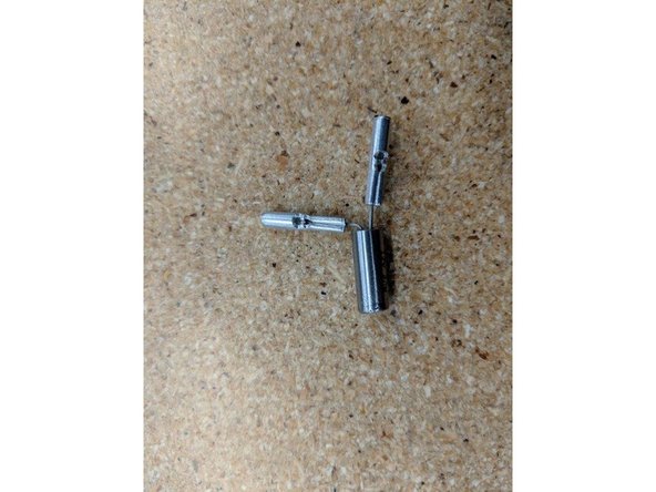
Place the first crimp on one leg of the cartridge. The leg of the cartridge will go to the mid point of the crimp shown.
-
Use the crimp tool to crush the HALF of the crimp that the leg of the cartridge is in. DO NOT crimp the entire length of the crimp as the wire will go in the other half.
-
Repeat the process on the other leg of the cartridge so both crimps are attached to the heater cartridge.
-
-
-
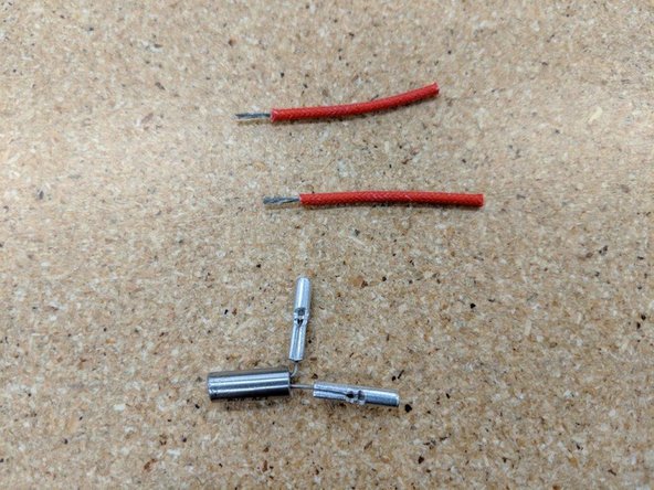
Locate the two red insulated wires in the kit and strip off the ends as shown in the first picture approximately as long as half the crimp. 7 mm works fine.
-
Insert the wires into the crimps and, as in the step before, use your crimp tool or pliers to crush the other half of the crimp attaching the wires to the crimp securely.
-
-
-
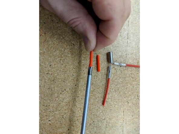
Locate the red silicone tube from the kit. Cut this tube in half so you have 2 pieces of equal length.
-
Use a screwdriver on one end of a tube to help open up one side. This will help get the tube over the crimps you just installed.
-
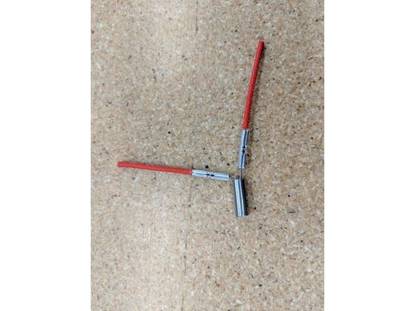
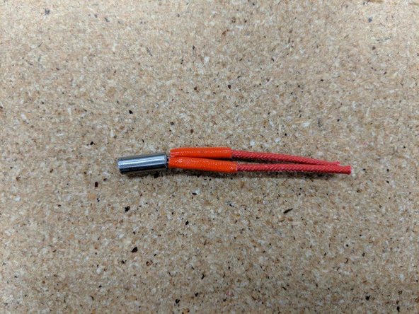
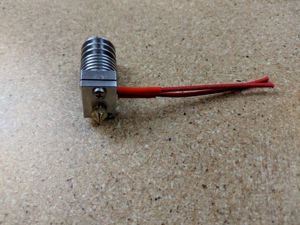
Slide one tube on one of the wires and work it down over the crimps until fully seated near the heater cartridge. Repeat this process on the other leg of the heater. The previous 11mm and 7mm cut lengths will give a result as in Pic 3.
-
Bend the leg of the cartridge so they are back in line with the cartridge. Pic 3 shows a fully prepped heater cartridge.
-
-
-
The main body of the hotend will come finger tight. Do not use this as assembled.
-
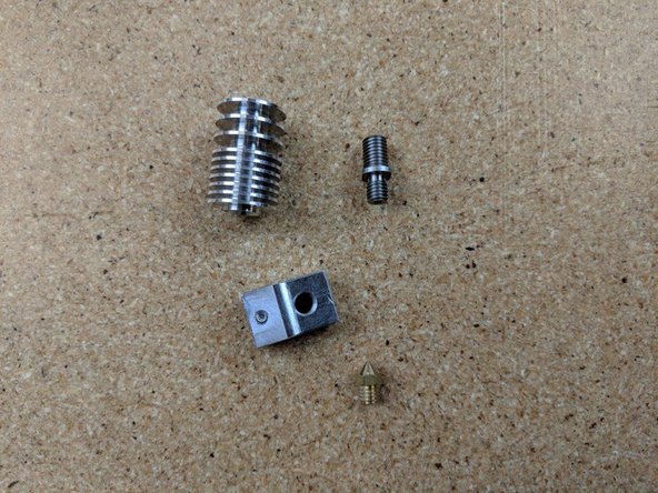
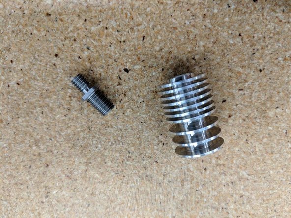
First remove the nozzle (should only be on finger tight when taken from the kit). Then unscrew the heater block. Finally unscrew the heat break. You should have 4 seperate pieces.
-
You should have the body disassembled as shown in Pic 2.
-
-
-
Locate the heat sink and heat break from the parts you just dissembled in the previous step.
-
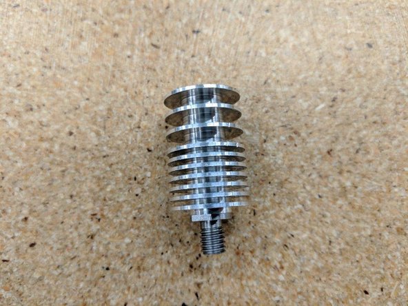
Screw the heat break into the heat sink into the side with multiple closer fins as shown in pic 2.
-
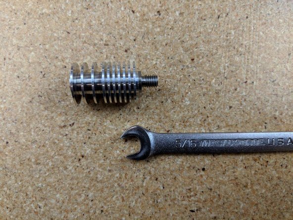
The heat break has 2 flats on it used to tighten it. Use a 5/16 wrench or an adjustable wrench and securely tighten the heat break to the heat sink.
-
-
-
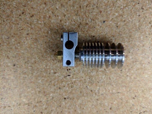
Locate the heater block, nozzle, and heatsink body you just disassembled.
-
The HEAT BRAKE and NOZZLE meet in the middle of the HEATER BLOCK.
-
The heat brake screws into the heat block into the side opposite of the screws
-
Screw the heat break and heatsink into the heater block watching the threads of the heat break until the end of the threads are just about even with the the heater block.
-
Screw the nozzle into the heater block on the side with the screw and set screw as shown in pic 1.
-
Use an adjustable wrench or 1/4" socket or 6mm socket to tighten the nozzle. The nozzle tightens against the heat break to create a seal inside the heater block.
-
-
-
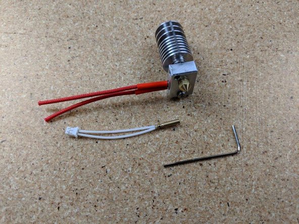
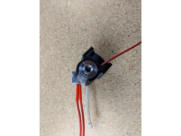
Insert the heater cartridge into the heater block. The wires from the heater cartridge should exit the same side the set screw is on that holds the thermistor in place.
-
Tighten the screw to secure the heater cartridge in place. You can use pliers to hold the block in place while tightening the screw.
-
Locate the thermistor cartridge and allen key.
-
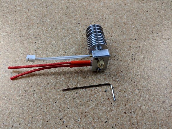
Insert the thermistor FULLY (you may need to loosen or remove the setscrew that is pre-installed so the thermistor cartridge can be fully inserted.
-
Use the allen key to tighten the set screw to hold the thermistor in place.
-
DO NOT OVERTIGHTEN the set screw for the thermistor. Once the set screw is snug, you only need to turn about 1/2 turn beyond to tighten. Over tightening can damage the thermistor
-
-
-
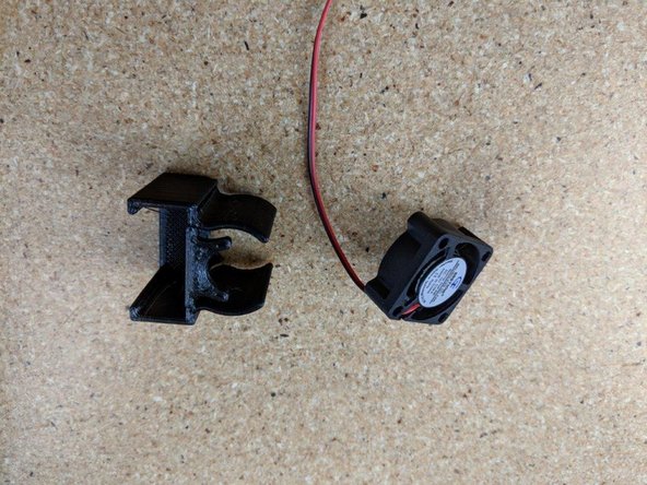
Locate the 25mm fan and fan shroud
-
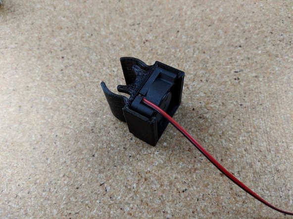
Insert the fan into the fan shroud as shown in Pic 2. The label on the fan should face the curved parts of the fan shroud and the wires should be at the top as shown.
-
You will use this fan shroud with fan and the hotend for the next step.
-
-
-
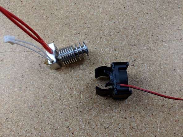
Insert the fan shroud over the heat sink . There is a tab on the fan shroud that inserts into the first large gap between the fins on the heat sink. Press this tab fully into the heat sink.
-
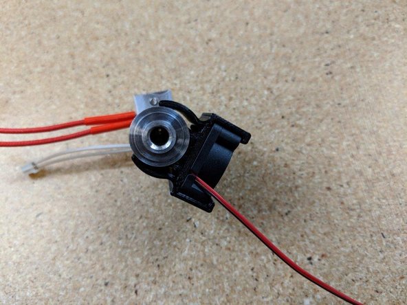
Rotate the fan shroud so it is positioned in pic 2. The fan should be approximately at the corner of the heater block opposite of the thermistor wires.
-
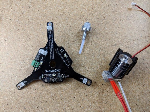
Locate the SE300 PCB, knurled locking connector and small PTFE tube from the kit as shown in pic 3 for the next step.
-
-
-
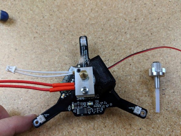
Position the hotend on the hotened PCB as shown in pic1. The fan will be under the 10 pin connector, and the wires for the thermistor and heater will be on the side with the green connector and 2 white connectors.
-
The heater block should be in line with the part of the PCB with the words silk screened on them, with the heater screw being on the side under the electronic components for the pcb.
-
On the PTFE tube, one side is tapered. This is the side that goes in the knurled finger screw and should be towards the top of the hot end.
-
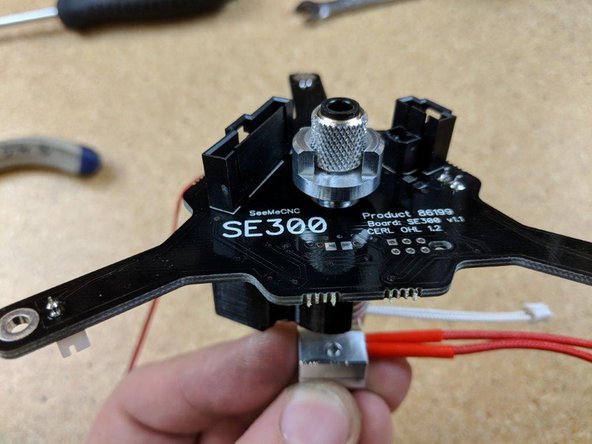
Holding the hotend to the pcb, flip it over and insert the PTFE tube and knurled finger screw into the hotend. Tighten this down with your fingers until it us JUST SNUG.
-
When you feel the knurled screw get snug, give it about 1/4 turn beyond snug ONLY, DO NOT OVERTIGHTEN!
-
with the knurled part snug, you can spin the collar of that section down to meet the PCB and tighten the assembly in place. This collar can be tightened securely and it will hold the whole assembly in place.
A plastic blue (in my case) tool is provided to help you tighten the collar.
David Anderson - Resolved on Release Reply
I had to go buy a 7mm - 1.0 tap to chase the threads so the knurled part would go in. Make sure you blow out any debris after you do this.
Vance Howard - Resolved on Release Reply
-
-
-
Plug the fan into the white connector labeled HeatFan (P7) as shown in Pic 2
-
Plug the thermistor into the other white connector labled on the board as P6
-
-
-
Bend the heater wires up so they are in line with the green connector
-
Trim the wires approximately even with the bottom of the PCB as shown in Pic 2
-
Strip the ends of the wires approximately 3mm (a little less than the height of the green connector as you do not want the wires exposed when connected.
-
-
-
Insert one of the wires into the green terminal block as shown in Pic 1 ensuring that no stray wires are sticking out. Using a small screwdriver secure the wire into the block and tighten securely.
-
Insert the second wire as the previous again ensuring there are no stray strands of wires . Again using a small screwdriver secure the wire into the terminal block.
-
Twist the fan wires as shown in Pic 3 .
-
-
-
Bend the twisted fan wires behind the thermistor and heater wires to keep them out of the way.
-
Bend the thermistor wires behind the heater wires to keep them in place and out of the way.
-
-
-
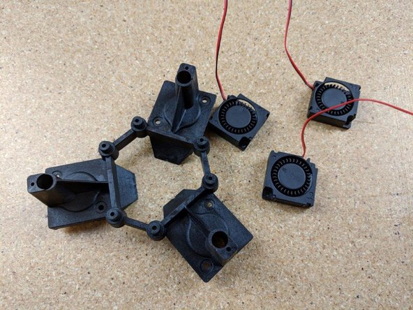
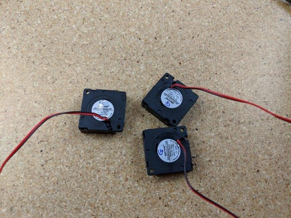
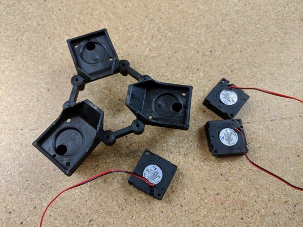
Locate the 3 blower fans and the hotend platform as shown in Pic1.
-
Gently bend the wires out of the plastic tab they are held on by.
-
Be careful when removing the wires from the tab as pulling on them can pull them out of the fan and damage the fan!
-
-
-
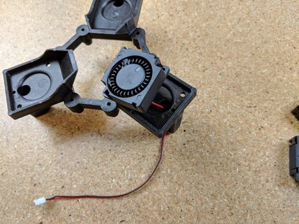
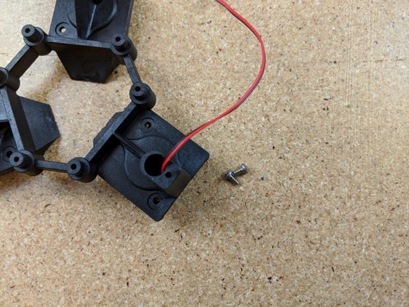
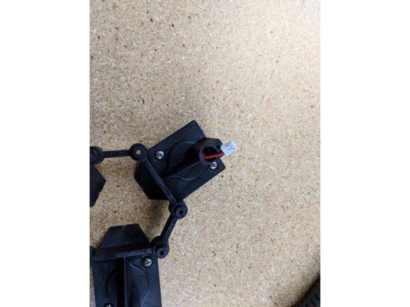
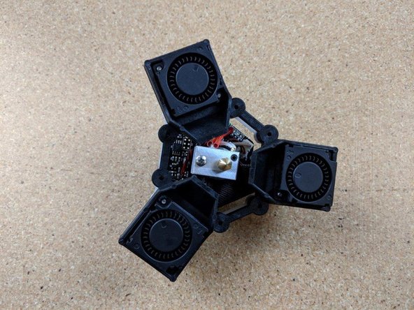
Insert the wire for the fan through the hole in the platform as shown in Pic 1. There is an arrow on the bottom of the fan showing the direction of airflow, this arrow should be aimed toward the center of the platform.
-
Over tightening the #4 screws will BREAK the fan mounting tabs. This IS NOT covered by warranty. Use care when installing the blower fans by not over tightening the screws.
-
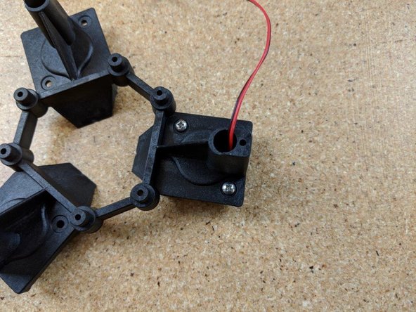
Using 2 of the supplied #4, 1/4" screws (the short ones from the kit) attach the fan to the platform. DO NOT over tighten these as they can strip out the fan. Only tighten them snug.
-
Repeat this process for the remaining 2 fans so all 3 fans are attached to the platform .
-
-
-
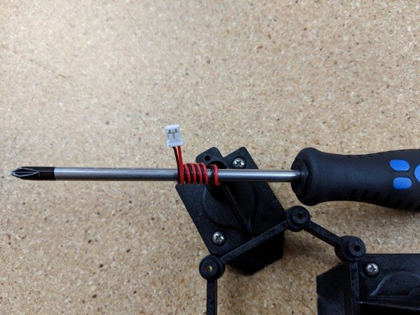
Be careful in this step not to pull on the blower fan wires as they can be damaged if pulled on.
-
Wrap the wires for the blower fans around a screwdriver or something similar that is smaller diameter than the hole the wires come out of.
-
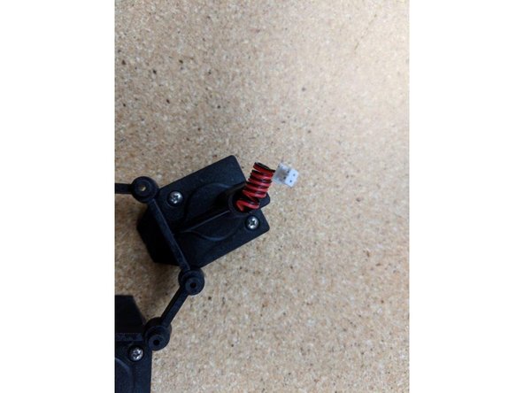
With the wire coiled up as shown in pic 2, you will shove the coiled wire into the hole to clean them so only a small amount of wire and the plug are sticking out of the platform.
-
-
-
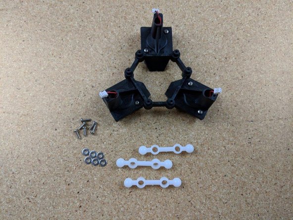
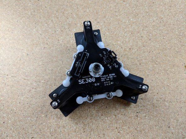
For this step locate the 3 white ball joint pieces, six #4, 3/8" screws, and six #4 washers.
-
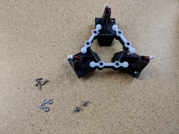
Press each ball arm over the mounting posts on the effector platform.
-
Fix each ball arm into place using two #4, 3/8" screws and two washers.
-
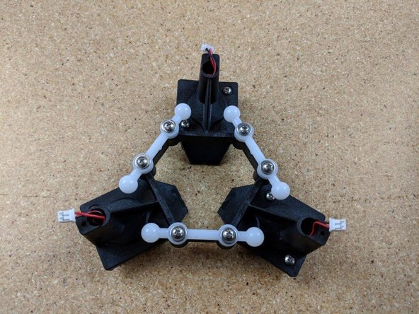
The completed assembly should look like the example in the last photo.
My kit came with 6 #4 x 1/4” screws, which seemed to be just fine for the ball joints.
Andrew Dunne - Resolved on Release Reply
-
-
-
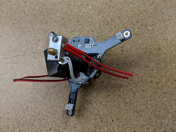
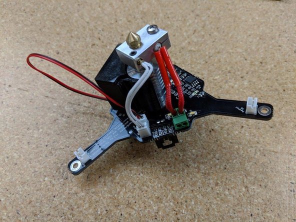
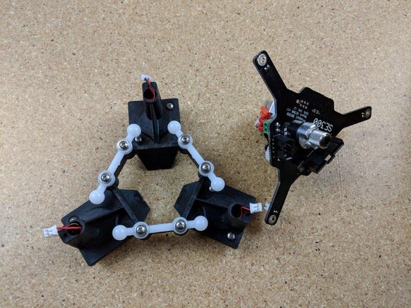
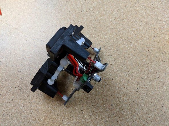
Locate the hotend and PCB, and the platform you just assembled.
-
Place the hotend over the PCB as shown in Pic 2.
-
-
-
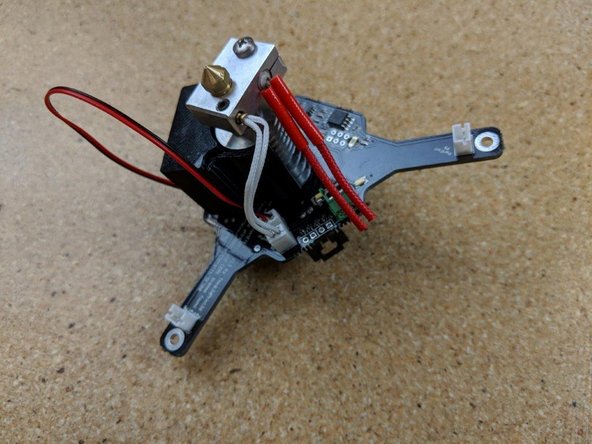
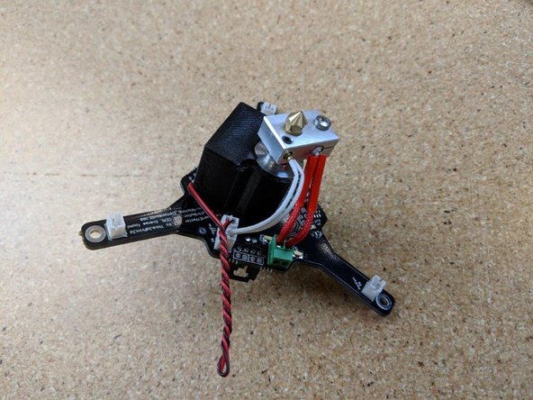
Locate the wires coming out of the platform along with the plug at the end of the PCB.
-
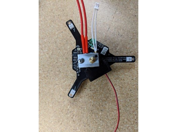
Plug the wires into the plug on the PCB as shown in Pic 2.
-
Repeat the steps with the remaining 2 plugs so all 3 fans are plugged into the PCB as shown in Pic 3.
-
-
-
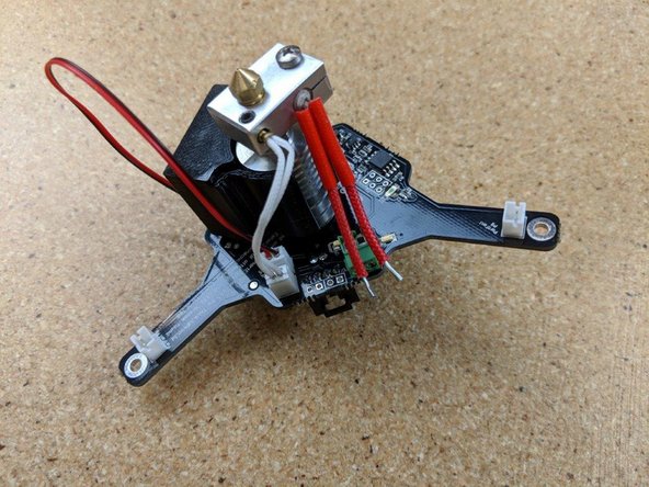
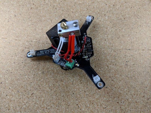
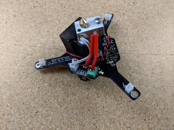
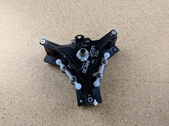
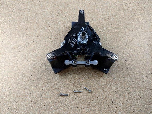
Locate three #4 1/2" screws (the longest ones in the kit) as shown in Pic 1.
-
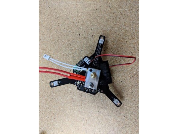
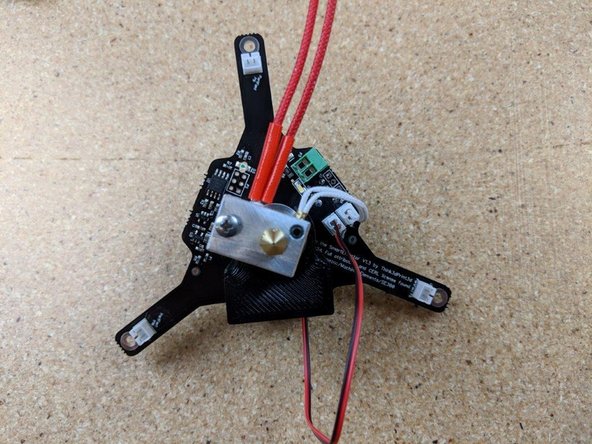
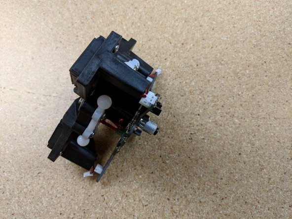
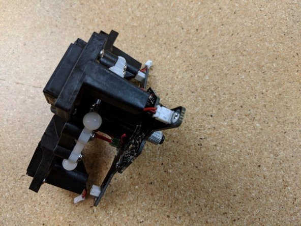
Line up the plugs on the platform and pushing the PCB onto the platform, the plugs should go into the holes they line up with.
-
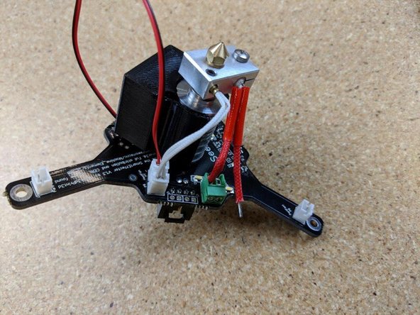
Attach the PCB to the platform using the #4, 1/2" screws at all 3 corners.
-
Your hotend assembly is finished and you have a fully asssmbled SE300 Hotend! Congratulations!
-


Cancel: I did not complete this guide.
16 other people completed this guide.
3 Comments
I think this guide needs to be linked to from the build guide for the Rostock Max v3.2 as my effector and hot end was not assembled.
Vance Howard - Resolved on Release Reply