
Introduction
This assembly guide will walk you though the steps of assembly the base of the Rostock Max v3 printer.
-
-
The first step in preparing for your build is to remove the masking from both sides of all laser cut panels. This masking helps protect the components during the cutting, packing, & shipping process.
-
-
-
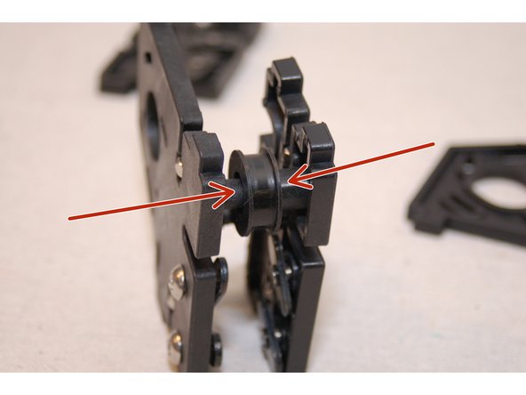
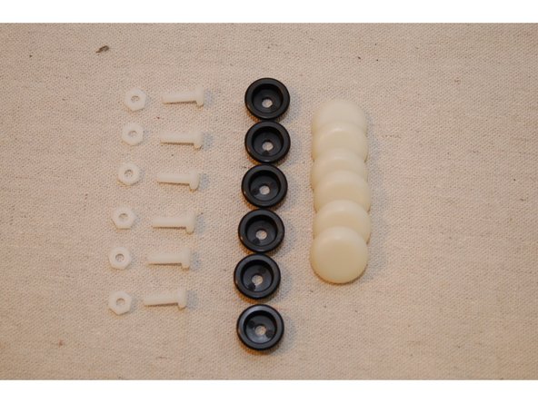
You'll be making three of these assemblies using injection molded parts 84407 & 84408 ( 1 each per assembly).
-
When inserting the nylon lock nuts, do so from the "inside" of the injection molded part. This will allow the nut to fit more easily into the nut pocket. Needle nose pliers make this a breeze.
-
Only thread the t-slot nuts on a few threads - you need to leave room for the tower channel to slide between the t-slot nut and the face of the injection molded mount.
-
The threads on the blind nuts have a flange on one side. The flanged side should be away from the head of the screw.
-
-
-
-
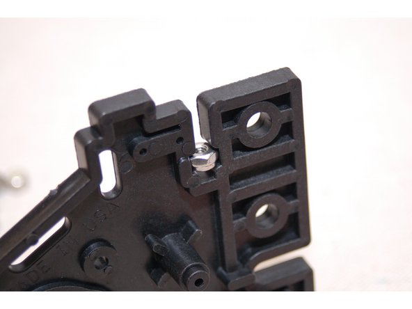
Insert the 6-32 nylon lock nuts into the injection molded parts first. There will be 2 of these nuts inserted per injection molded piece
-
Then install the 1/4-20 button head screws and T-SLOT nuts. Remember to only get the nut started on the screw.
-
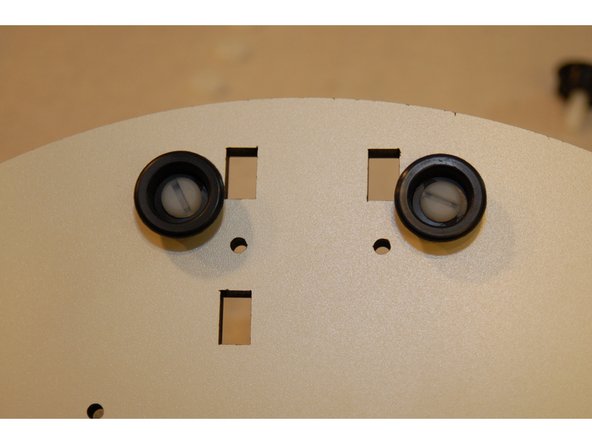
Press the bearing / cover assembly (pre-assembled by SeeMeCNC) onto the posts inline with the 1/4-20 hardware (position shown)
-
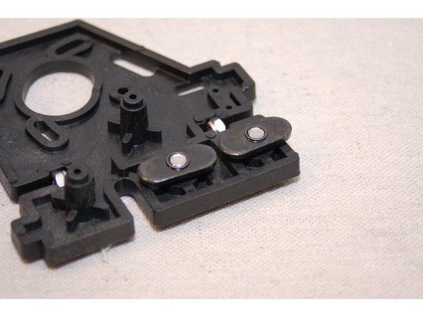
The two halves will be fastened together with #4 x 1/2"screws.
-
Complete 3 identical assemblies.
Note: There are a total of 4 lock nuts inserted per complete part, 2 in each half.
Steve Hansel - Resolved on Release Reply
This statement: ‘The two halves will be fastened together with #4 x 1/2"screws. ‘ sounds like information about what will happen in the future, not an assembly step. However I believe it should be the latter. Suggest: “Fasten the two halves together using 2 #4 x 1/2” screws.
Steve Hansel - Resolved on Release Reply
-
-
-
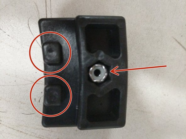
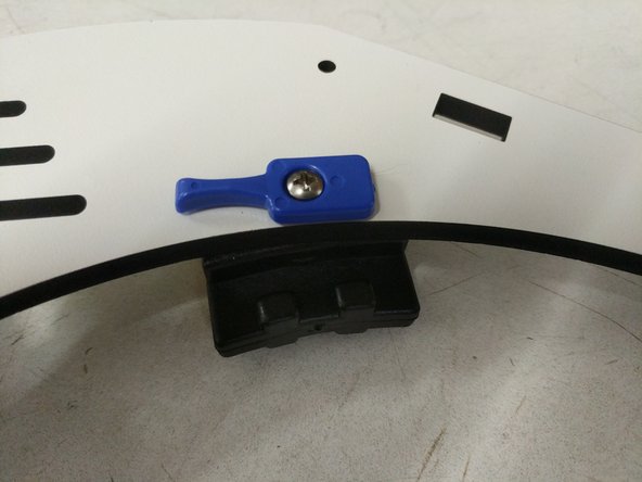
Insert stainless steel nylon lock-nuts into the side with circular marks.
-
Using 6-32 x 1" phillips pan head machine screws, gently tighten as shown. Blue bed clamps should rotate very easily, but not be loose.
-
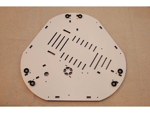
You will be installing 6 bed clamps and support blocks around the periphery of the hole in the center of the laser cut plate.
The bed clamps go on the side of the plate with “ROCKSTOCK MAX V3” on it. The lock nuts need to be pushed into the hole quite far with a screw driver, or the screws won’t reach them.
Steve Hansel - Resolved on Release Reply
-
-
-
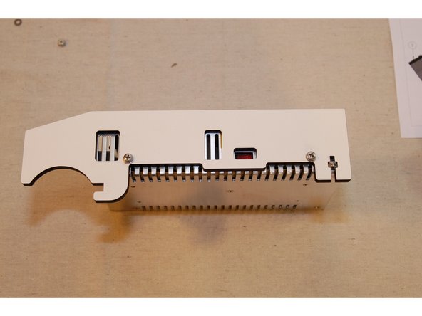
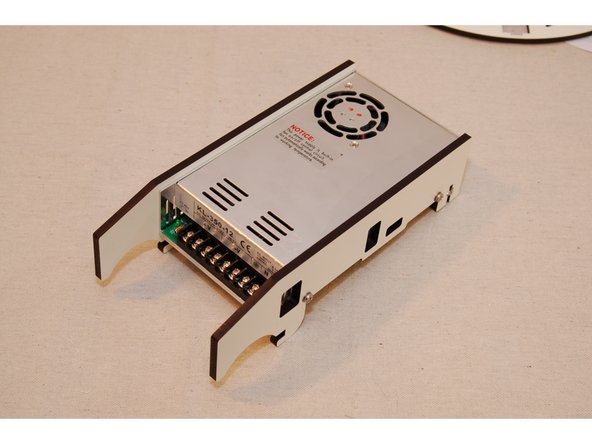
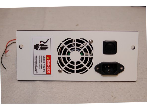
Install the PSU Blocker sides using (2) M4 x 12 screws and washers per side (In base electronics hardware pack - 84493).
-
WARNING: Don’t forget the washers in this step! The 1mm spacing they provide prevents the screws from contacting electrical components on the inside of the PSU. Failure to include these washers can cause the PSU to fail.
-
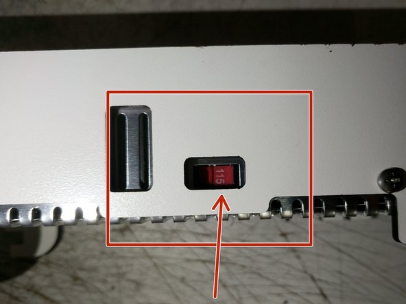
If you are located in the US, make sure the 220/110 switch is in the 110 (115) position, as indicated by the arrow. This defines the input voltage the power supply expects.
-
If you're in a country where 220v is the standard, make sure the switch is on the 220 setting.
I really can’t determine how it is from the picture but my instinct was to put the washers under the screw heads. However, I later found putting the washers between the power supply and the PSU Blocker helped space the Blocker enough to engage the base plate in Step 12. Your mileage may vary.
Dieter Weik - Resolved on Release Reply
In step 12, the lock nuts in the slot, shown in the photo, but not mentioned, are required. Fortunately they are easy to install after the fact.
Steve Hansel - Resolved on Release Reply
-
-
-
Make sure you don't over-tighten the nylon fasteners. They can be easily damaged if you over-tightne
-
You may wish to leave the soft rubber feet off until you've completed the assembly of your Rostock MAX v3. The soft feet have a strong grip to them and can make turning the printer difficult.
-
-
-
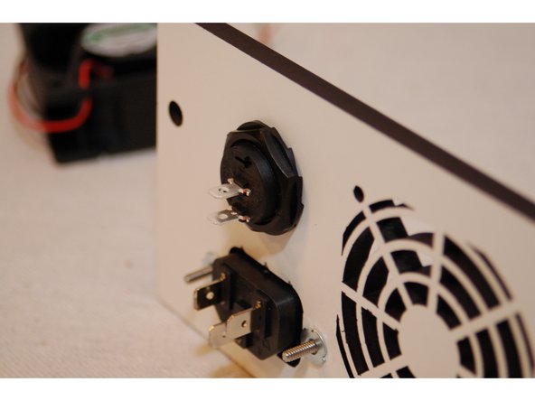
When installing the power switch, ensure it's in the "off" position by setting the switch so that the "low" point of the rocker is closest to the terminal near the edge of the switch.
-
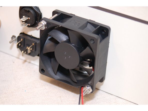
The power supply cooling fan has both rotation and airflow direction marks on the side of the fan. Make sure that the airflow direction arrow points towards the panel.
-
Don't forget to apply the safety warning sticker!
Since mine is the second last available, not much of a chance of getting better instructions, for this version, the V4 model is completely revised. Tried to do an inventory of supplied parts, —complete waste of time truing to read the ultra-fine microprint on each bag without a microscope! . Seems they are running with the China policy, offer a “new and improved version, a-la V4- screw the rest. Remove parts that cause head-aches, e.g. incompatible display with the 32 bit duet! Doubt anyone will read this.
Stef
is.chowa@gmail.com - Resolved on Release Reply
I believe hardware is from package 84493 “Rostock Max V3 Base Electronics H/W pack”.
2x 6-32 x 1.75” Phillip Pan Head Screws. Stainless
2x 4-40 Blind T-Nut (zinc plate)
2x 4-40 x .75” Phillip Flat Head Machine screw. Stainless
The “off” position of the switch: Note the two connection terminals on the back are offset from center. When the switch rocker is positions such that the low point aligns with these terminals the switch is off.
Dieter Weik - Resolved on Release Reply
Not to complain (but I am). But by this point the quality of the instructions has gone completely downhill. Especially for a $1000 kit. The beginning instructions were great, telling you exactly what bolts/nuts/etc to use along each step of the way. The last few (and this one is a perfect example) are nothing like that. You have a low resolution video showing it going together, (which you can't read any text from), and then a few tips & final photos listed here. Nowhere did it say what screws to use, what nuts,etc. Had to do the 'rong ones' a couple times here before I realized the right bolts for the power plug (and that it used the T-nuts)
-
-
-
Attach the PSU to the base plate using (2) 6-32 x 1" screws.
-
-
-
-
This animation will provide you with an overview of what will be assembled.
-
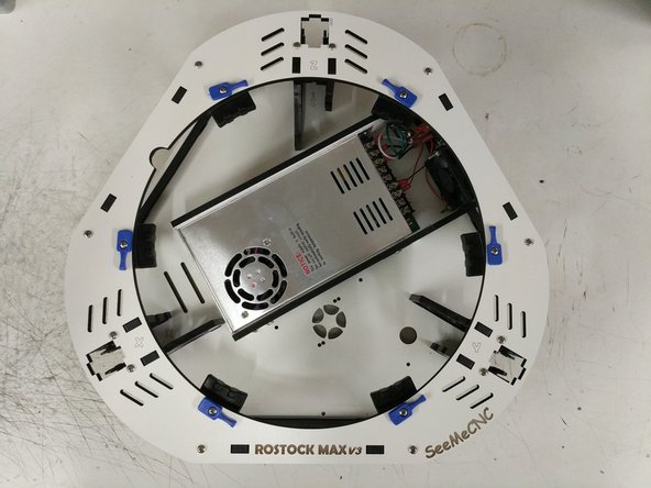
Assemble all components / sub-assemblies to the base plate first. Then install the top plate. All fasteners used are 6-32 x 1"
Pay attention to the rotation of the top plate relative to the power supply. It’s symmetrical except for the label.
Steve Hansel - Resolved on Release Reply
I used a flathead screwdriver to pry the nut slots open. This made the insertions go a lot faster.
jay armstrong - Resolved on Release Reply
-
-
-
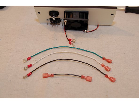
Add connectors to the 200mm and 75mm wires as shown.
-
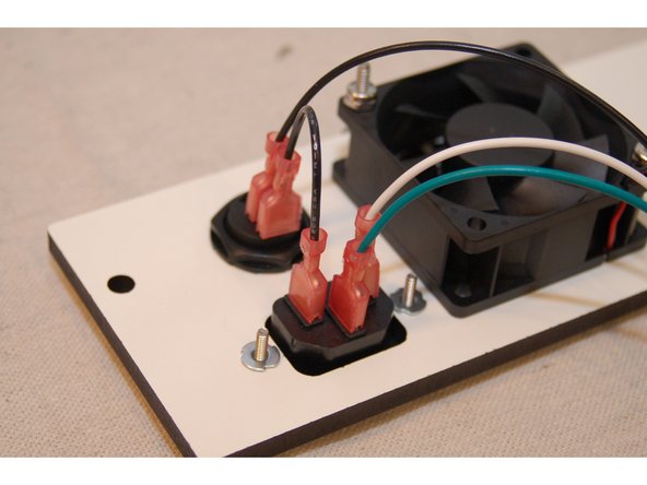
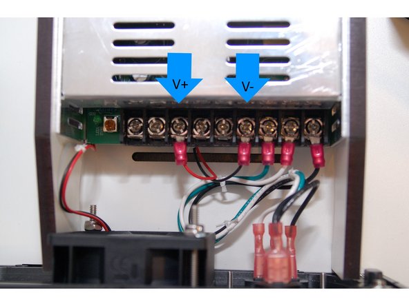
The red & black wires for the cooling fan are connected to the first terminal in the V- and V+ sections as indicated by the blue arrows.
-
Secure the panel to the base assembly using (2) 10-32 socket head cap screws. The holes in the injection molded side panels are not tapped / threaded. Make sure you put some pressure on the screws and keep them straight.
-
Make sure you put some pressure on the screws and keep them straight. They will be a little difficult to get started, but will go in perfectly with a little pressure. The screws will go in much easier the second time.
Once I realised I needed to thread those holes in the Base Assembly, I did the threading BEFORE assemby, placing them flat on the table and working in the 10-32 screws. Did that for all 3 Base Assemblies. It’s a breeze mounting the panels later. Actually, instead of 10-32 machine screws, I think self-tapping screws for wood or plastic would have been more appropriate.
BEWARE! Don’t touch those 10-32 screws after you’ve turned them in or out for a while. Friction/stiction makes them REALLY HOT to the touch.
Just chuck up an Allen head in your small electric screw driver and the screws will go right in.
Dieter Weik - Resolved on Release Reply
I found using a round file on the openings of the holes in the injection molded side panels made starting the 10-32 socket head cap screws much easier. Basically just scuff up the first 1 to 2 mm of the hole and you can start the screw by hand, then use a tool to drive it in.
Bill Felkner - Resolved on Release Reply
-
-
-
Congrats! The base assembly is now complete. We will focus on the top assembly next.
-
-
-
This Sub-Assembly can be set aside until Step 4. Rostock Max v3 Final Assembly.
-
Proceed to: Step 3. Rostock Max v3 Top Assembly
-
Cancel: I did not complete this guide.
14 other people completed this guide.

One Comment
For steps 2 and 3 you need the bage 84495 Rostock Max v3 Idler Hardware Pack.
Adam Ruthford - Resolved on Release Reply
When you are seperating all the parts from the laser cut panels, throw all the little scraps in a ziplock bag and keep them until the end of the project. There are a few small parts you may not recognize as being needed right now. At the end when you need them, you can go to the bag.
Steve Hansel - Resolved on Release Reply
I believe this section needs parts form hardware bag 84495.
Steve Hansel - Resolved on Release Reply