
Difficulty
Moderate
Steps
50
Time Required
04:00:00

User-Contributed Guide
This guide is not managed by the site's staff.
Quiz
0
-
-
Please note that we do not suggest upgrading the hotend of machines with the ATX power supplies as the computer power supply may be unreliable with the HE280. This upgrade will be done at your own risk and HE280 machines with an ATX power supply will not be supported by our support department.
-
Proceed at your own risk. This upgrade may cause power supply failure resulting in replacement of the power supply unit.
-
-
-
If you purchased a fully assembled HE280 Hotend you can continue. If you purchased the hotend as a kit and have not assembled it yet, please perform that assembly now (starting on step 9): HE280 Hotend Assembly After Assembly, continue with this How-To Guide.
-
Remove power cable(s), USB, etc from the printer and clear a suitable work-space for performing the upgrade.
-
Remove the LCD bezel from the front of the printer.
-
-
-
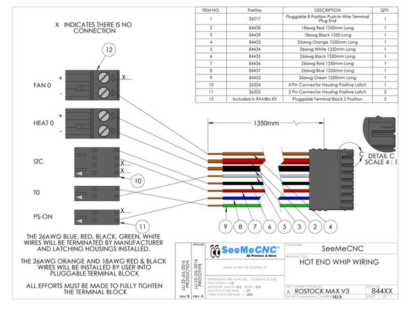
If you purchased the Hotend Whip from SeeMeCNC, it is fully assembled. For upgrading Rostock machines, it will require some modification.
-
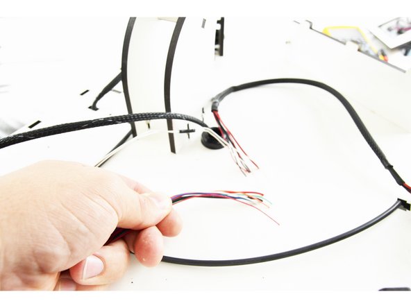
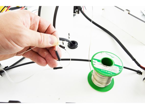
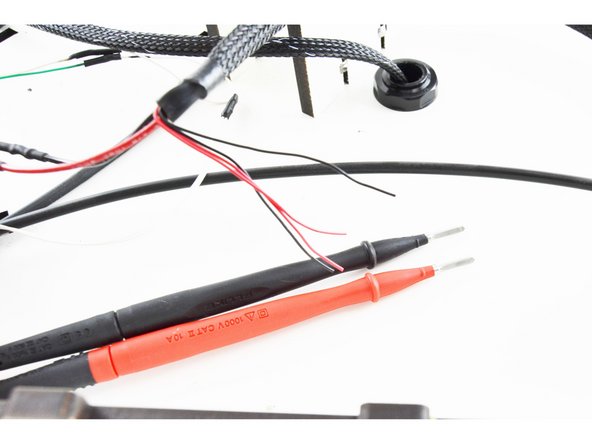
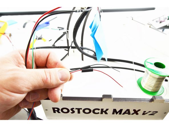
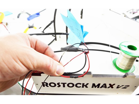
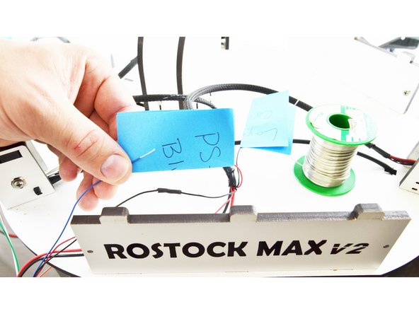
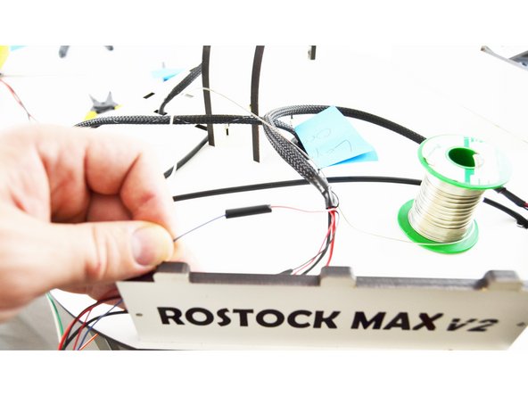
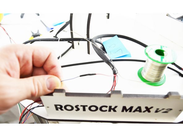
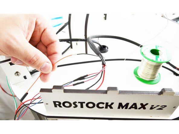
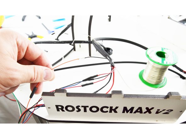
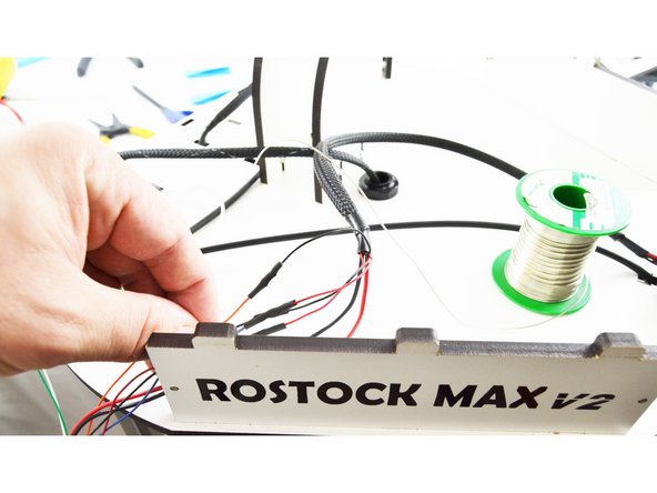
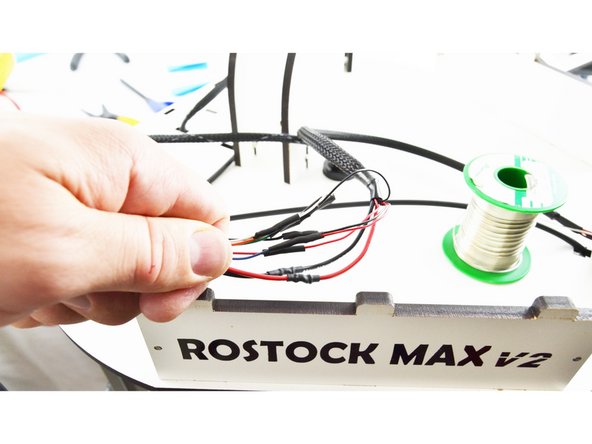
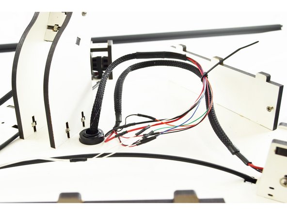
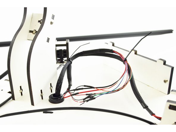
One end of the whip has an 8 pin pluggable connector, the other end has (2) 2 pin connectors & (1) 4 pin connector.
-
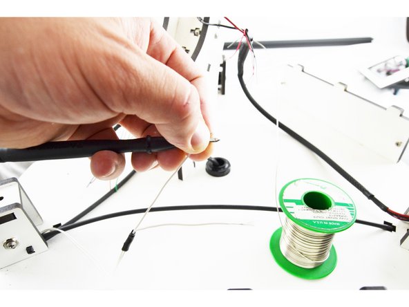
On the side that has (2) 2 pin connectors & (1) 4 pin connector, measure and cut all 8 of these leads approximately 125mm from the end. (they are cut slightly longer in the picture)
-
-
-
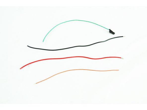
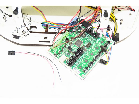
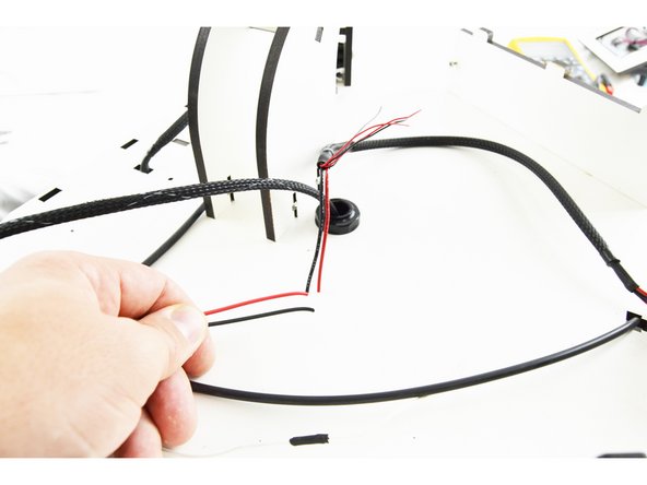
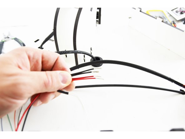
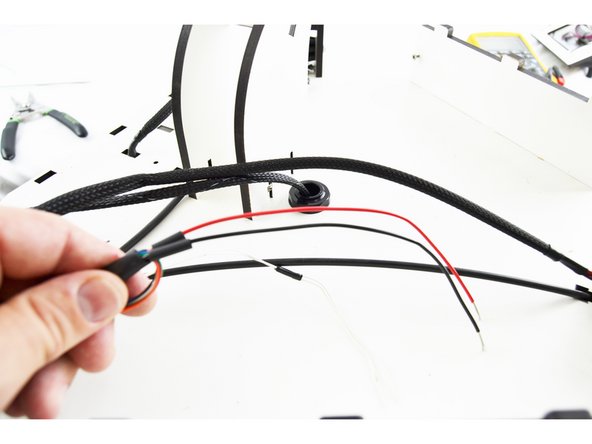
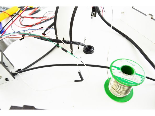
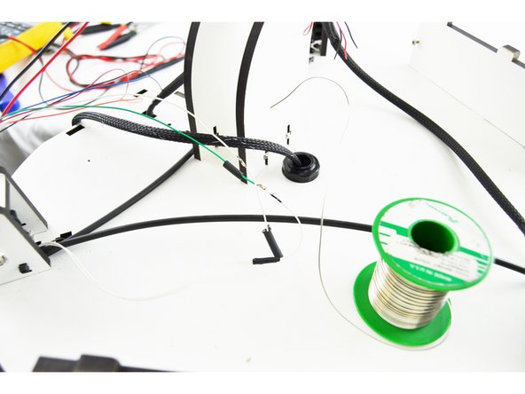
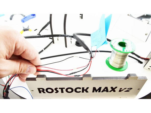
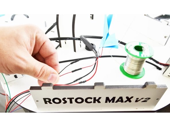
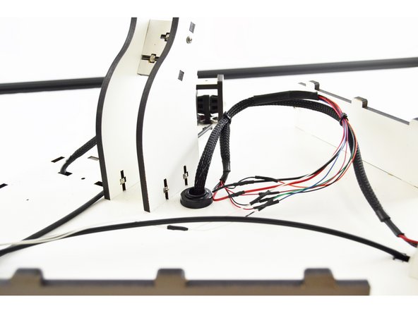
The wires shown in this image are not going to be used on your upgrade. You may find them helpful if ever performing other work, especially the green/white pair that are pre-terminated and in a 2 pin latching housing.
-
-
-
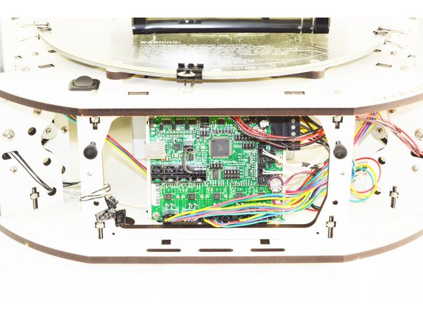
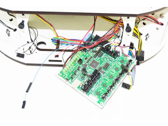
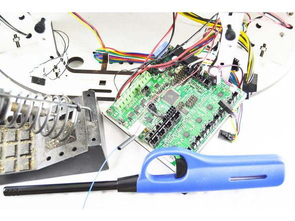
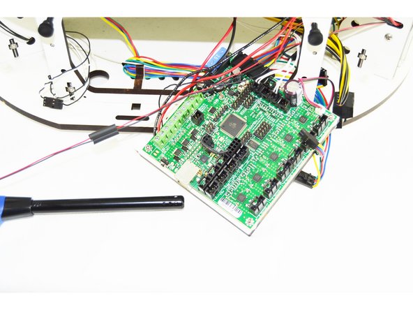
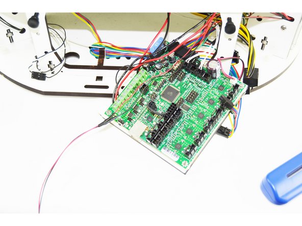
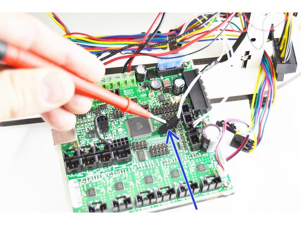
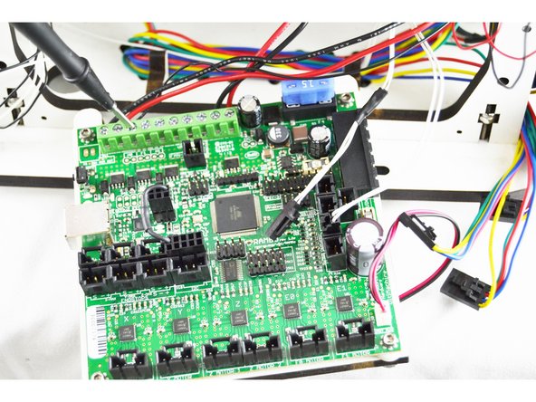
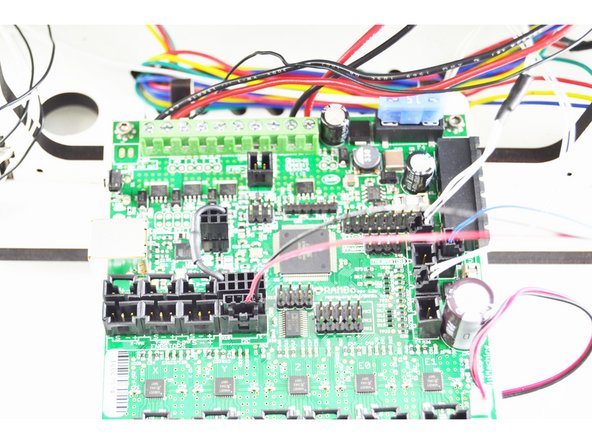
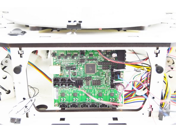
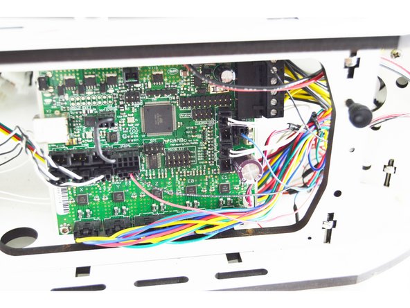
disregard the black jumper wire in the middle of the RAMBo board shown in the picture.
-
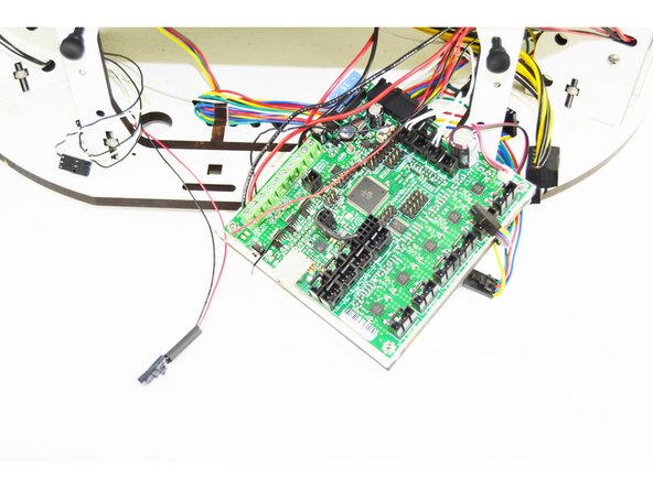
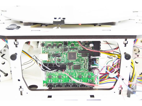
Remove the end-stops from the RAMBo board one at a time. If they are not already labeled, please label them as you remove them. From left to right they should be labeled X Y Z
-
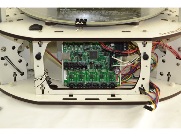
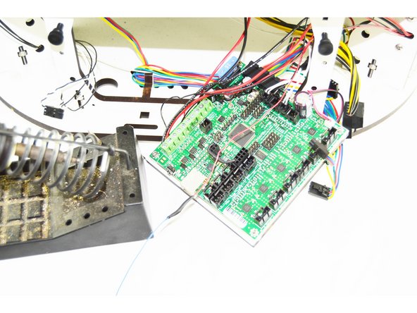
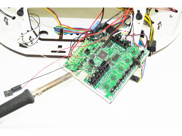
Remove the stepper motor wires from the RAMBo board one at a time. If they are not already labeled, please label them as you remove them. From left to right they should be labeled X Y Z _ E0 _
-
-
-
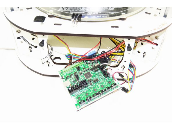
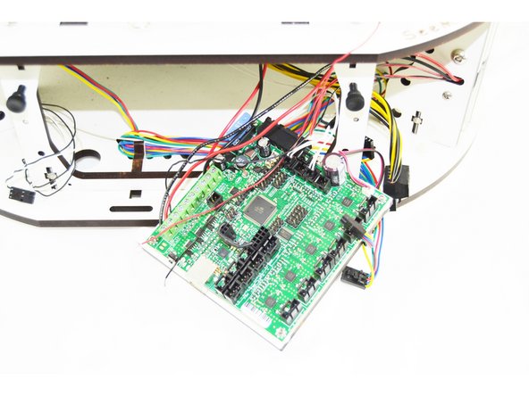
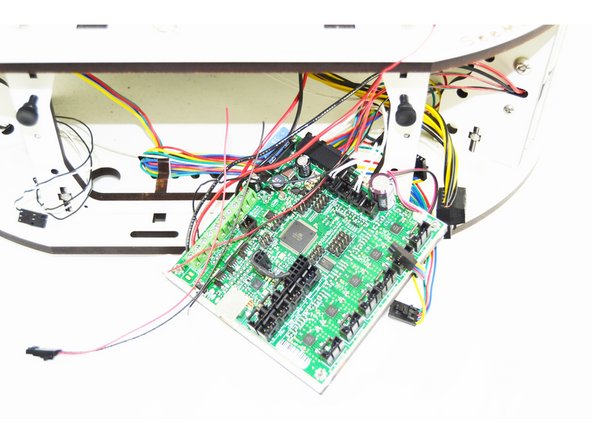
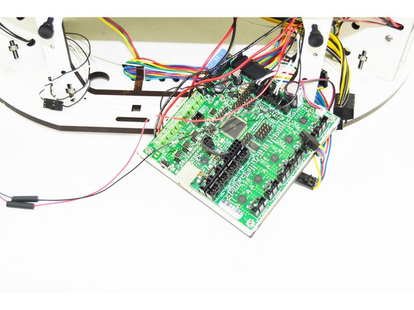
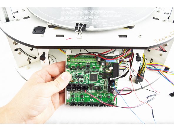
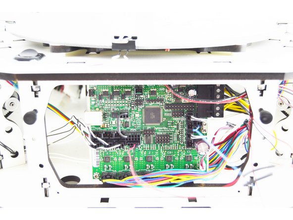
The RAMBo board is mounted to a backer board. You will grasp that backer board on the bottom left and right pull out. The bottom of the RAMBo (and backer) should pull freely and tip out. Once the top ears on the backer board have cleared the top plate of the base, the entire board can be removed.
-
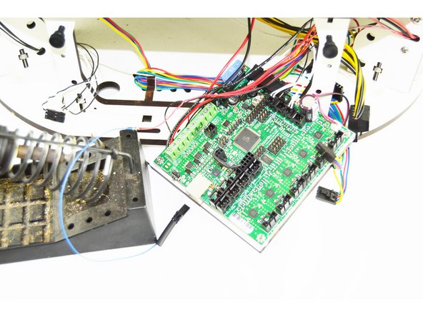
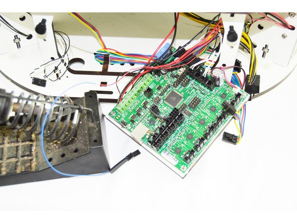
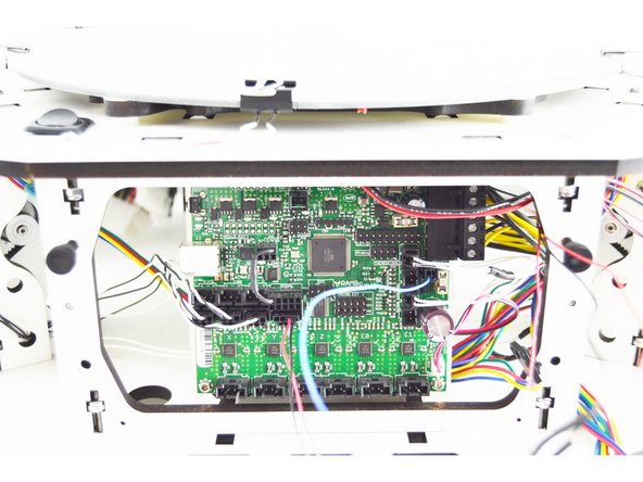
Remove the 6 pin pluggable terminal block from the RAMBo board. (This terminal block has the wires that come from the power supply)
-
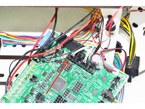
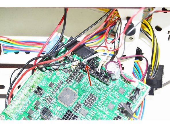
Loosen and remove ONLY the wire from the Fan 0 + terminal on the top of the RAMBo board.
-
-
-
If your Fan 0 wires are knotted (like the ones here) and there is not enough excess room to work with the + wire, take a minute and get those wires separated.
-
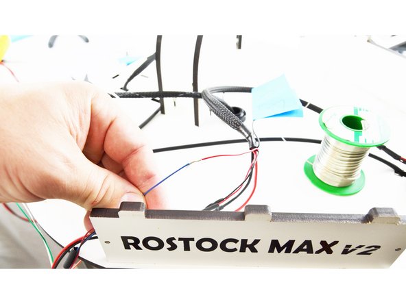
Locate the BLUE 26awg wire that you cut from the Hotend Whip. This wire is already inserted into a 2 pin latching housing.
-
Strip approximately 10-15mm of insulation off of the blue wire.
-
Strip approximately 10-15mm of insulation off of the wire that was previously in the Fan 0 + location.
-
-
-
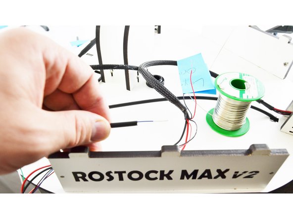
Cut a piece of heat-shrink at 15mm. (This was included with the hot end whip)
-
Slide the 15mm long heat-shrink tubing over the blue wire.
-
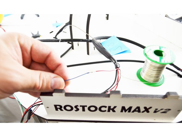
Perform an in-line splice of the blue wire and the wire that was previously in the Fan 0 + terminal.
-
Solder the connection.
-
-
-
Slide the heat-shrink up over the connection that you soldered and heat it with a lighter.
-
Do not allow the heat to be concentrated in one place for too long.
-
The heat-shrink will shrink down over the connection.
-
-
-
Remove the wires from the Heat 1 - & + terminal.
-
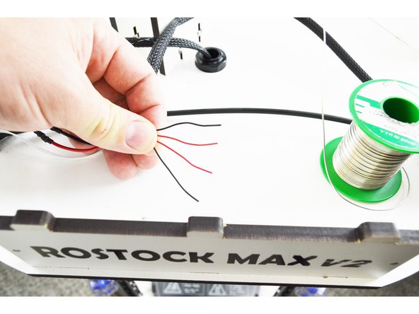
Locate the Red and Black 26awg wire that you cut from the Hotend Whip. These wires are already inserted into a 4 pin latching housing.
-
Strip approximately 10-15mm of insulation off of the black and red wires (with that are in the 4 pin latching housing).
-
Strip approximately 10-15mm of insulation off of the wires that were previously in the Heat 1 - & + locations.
-
-
-
Cut 2 pieces of heat-shrink at 15mm each. (This was included with the hot end whip)
-
Slide a 15mm long heat-shrink tubing over the red wire that is in the 4 pin latching housing. (as shown in the picture)
-
Slide a 15mm long heat-shrink tubing over the black wire that is in the 4 pin latching housing. (as shown in the picture)
-
Perform an in-line splice of the wires, Red to Red, Black to Black.
-
Solder the connections.
-
-
-
Slide the heat-shrink up over the connections that you soldered and heat it with a lighter.
-
Do not allow the heat to be concentrated in one place for too long.
-
The heat-shrink will shrink down over the connection.
-
-
-
Up until this point the thermistor wires polarity has never mattered. However, with the new probing PCB polarity DOES matter. We need to differentiate between the positive and the negative.
-
Locate the thermistor leads that are in the T0 location on the RAMBo board.
-
Label the wire with a sharpie marker or similar) that is on the the bottom (closest to the stepper motor ports). This is the "Positive" wire and for the sake of explanation will be connected to the green wire in the top of the machine.
-
-
-
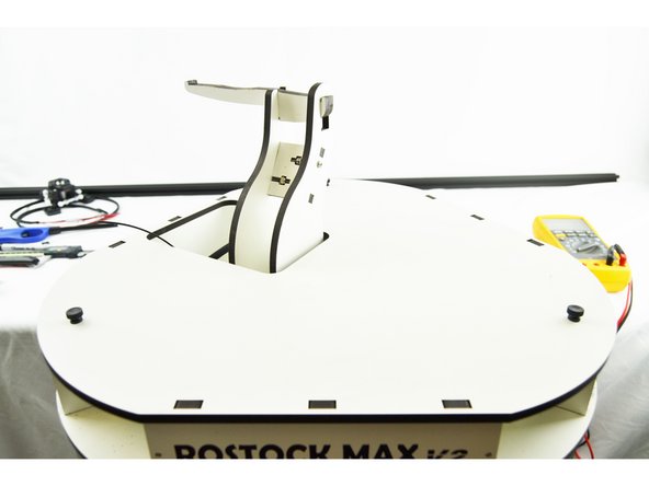
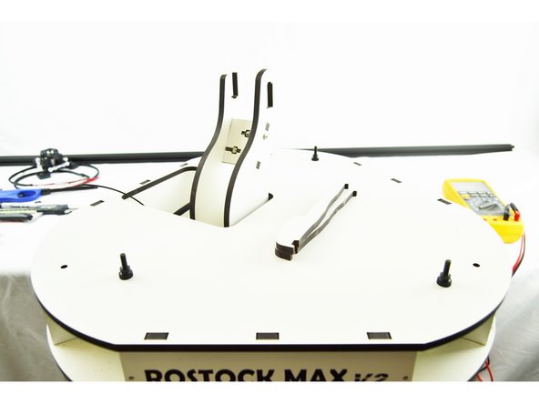
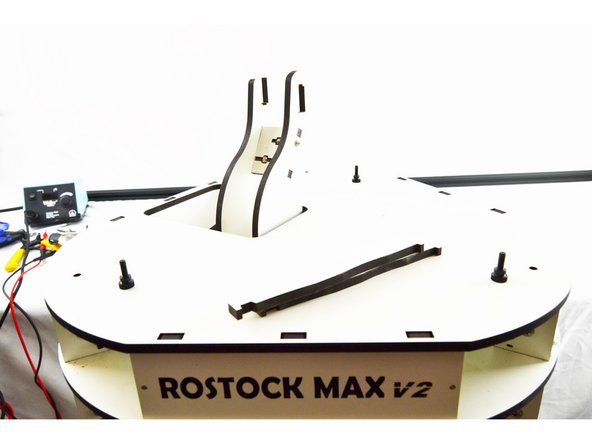
Remove the spool holder arms.
-
Remove the three thumb screws that fasten the top plate to the rest of the printer.
-
Remove the top plate from the machine.
-
If you have a Rostock Max v1, this step is not necessary.
-
-
-
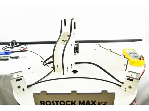
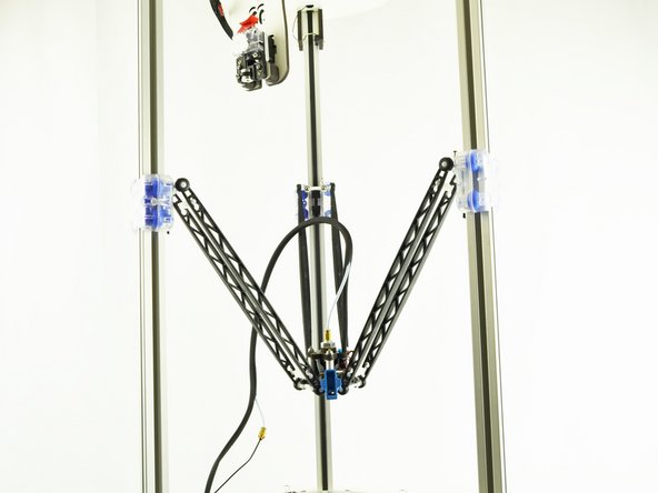
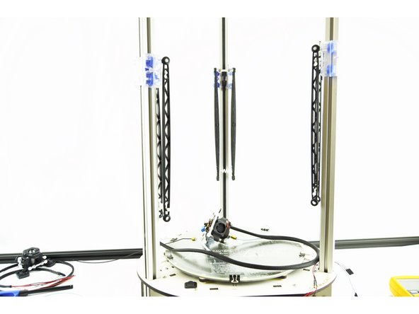
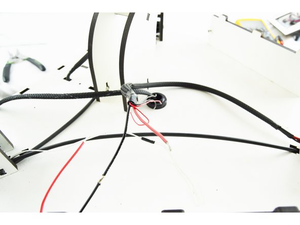
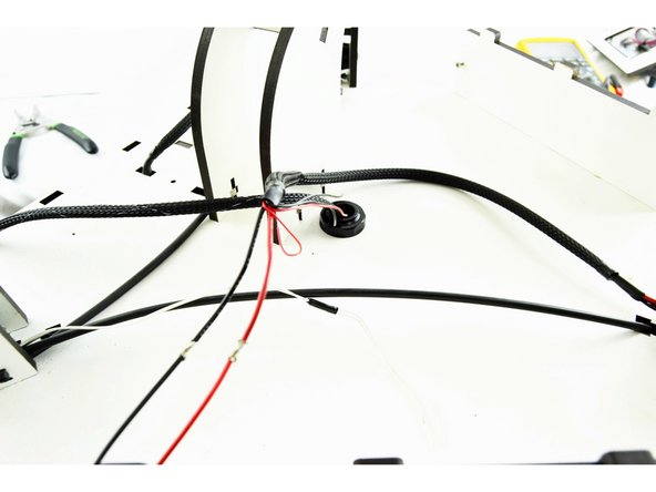
Determine the best location to cut the exitising hotend wiring/whip. There needs to be sufficient wiring left in the top of the machine to make splices with the new hot end whip. You can see in the picture where the wires for this particular Rostock v2 were cut (next to the extruder).
-
DO NOT ACCIDENTALLY CUT THE STEPPER MOTOR WIRES!
-
-
-
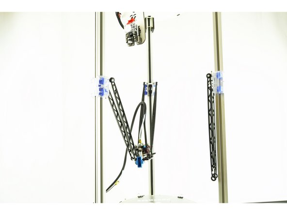
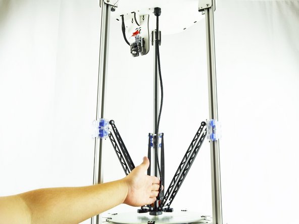
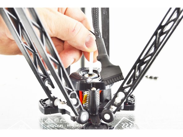
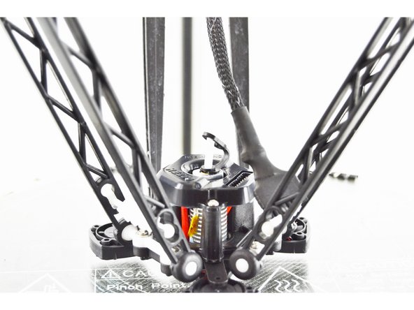
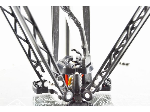
Remove the ball joint arms from the hotend platform. Do one set at a time, until you have all of the arms disconnected.
-
Remove the PTFE/Bowden tube from the extruder.
-
Your hotend and platform can now be completely removed from the printer.
-
-
-
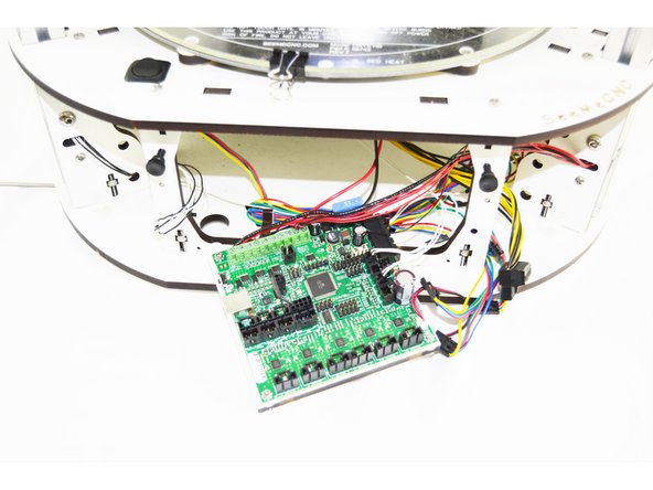
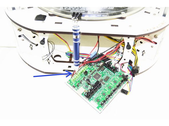
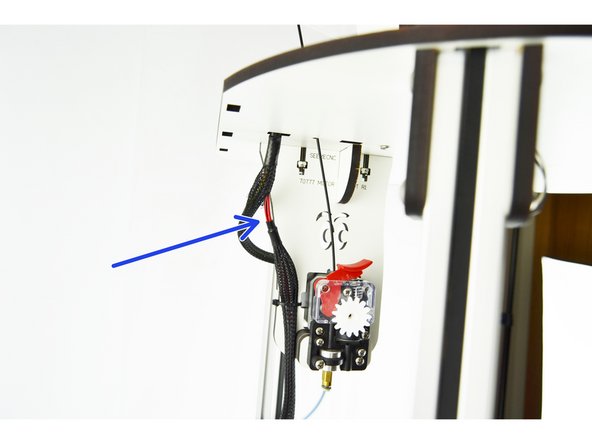
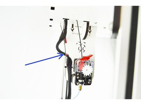
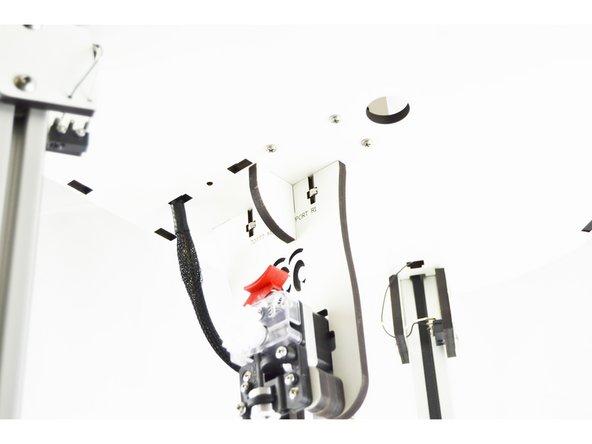
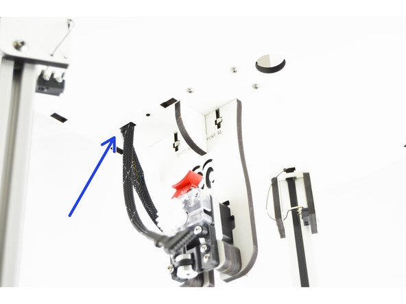
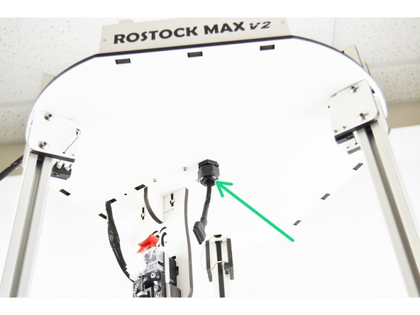
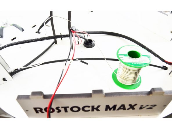
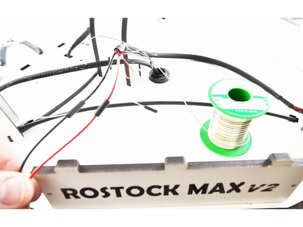
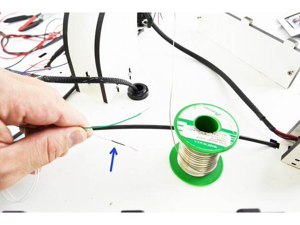
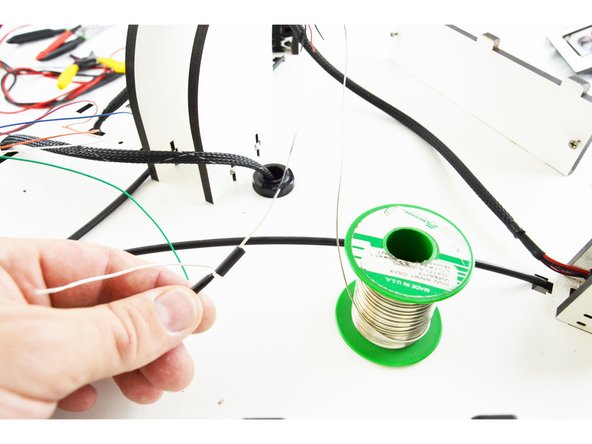
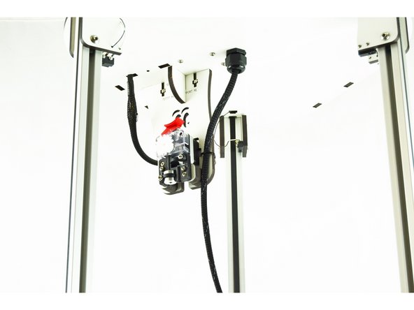
Choose the location that you want to route the new hotend whip.
-
In the pictures I show two locations. The location with the blue arrow shows where the original whip was routed.
-
The location with the green arrow is where I chose to route the hot end whip. (note.I used a panel mount strain relief, not included)
-
Ultimately the choice is up to you.
-
Run the new hotend whip through the top plate. You will need to route the end of the whip without any connector up through the plate.
-
At this point it does not matter how much of the whip is below the top plate. There needs to be plenty of slack in the top though to perform the required solder connections.
-
-
-
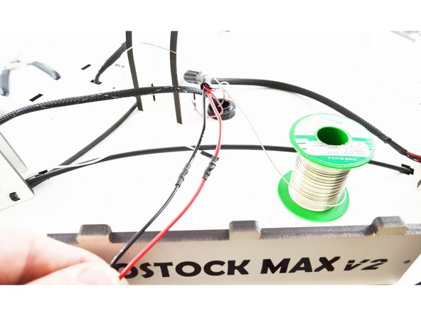
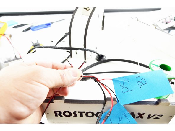
You can see here in the picture that we have a bundle of 8 wires from the new hotend whip and 8 wires from the exiting wiring. In the following steps we are going to work on getting these connected.
-
In preparation, strip approximately 10-15mm on insulation off of each of the 16 wires, cut your remainging heat-shrink tubing into pieces that are 15mm long, have a multimeter handy, and pay close attention to the steps.
-
-
-
Locate the 18awg wires from the existing wiring (in most instances these wires are red and black) and the new hotend whip.
-
The connections will be red to red, black to black. (If you have wires that are other than red/black for your existing 18awg wires, you will need determine which is positive and negative. These are the Heat 0 wire from the RAMBo)
-
Slide a piece of heat-shrink tubing over one of the red wires and one of the black wires.
-
-
-
Slide the heat-shrink up over the connection that you soldered and heat it with a lighter.
-
Do not allow the heat to be concentrated in one place for too long.
-
The heat-shrink will shrink down over the connection.
-
-
-
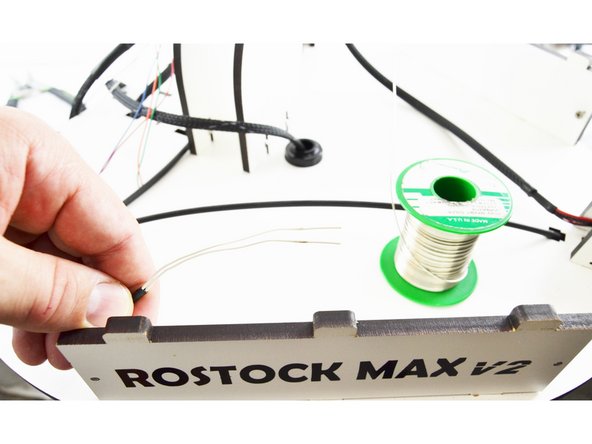
Locate the existing thermistor wires.
-
If you have not already, strip 10-15mm of insulation from the wires.
-
-
-
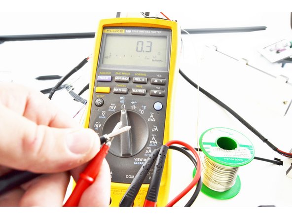
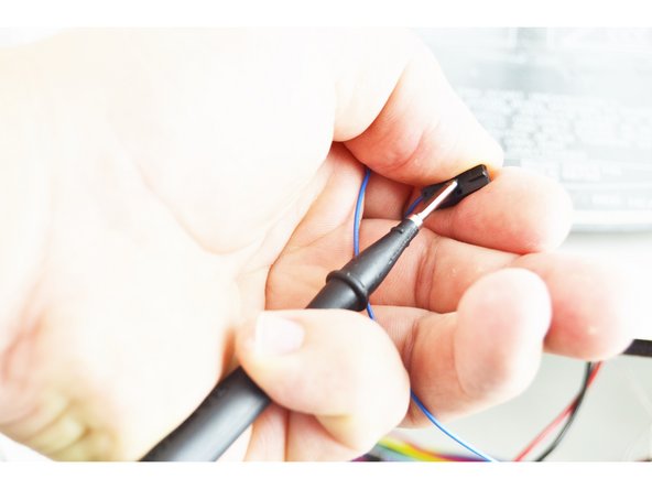
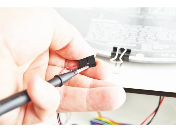
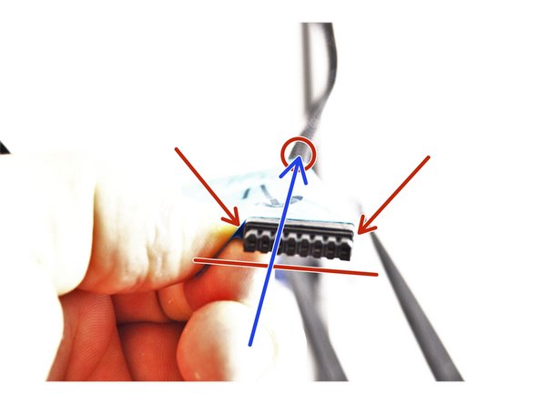
Use your multimeter to determine the polarity of the thermistor leads. You need to label the existing thermistor lead in the top of the printer The same as you labeled it in the bottom of the printer. This lead will eventually be soldered to the GREEN wire from the new hotend whip.
-
Contact the probe from your multimeter against the metal tab in the latching housing as shown in the picture with the blue arrow.
-
Be sure to label the thermistor wire! Polarity does matter!
-
-
-
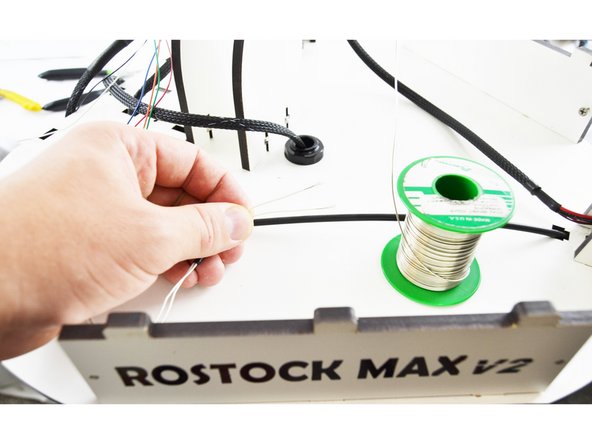
Notice in the first picture that the lead has been marked. (labeled with a blue arrow). This lead will be soldered to the green wire from the new hotend whip.
-
Slide a piece of 15mm long heat-shrink tubing over one of the wires.
-
Slide another piece of 15mm long heat-shrink tubing over one of the wires from the second pair of thermistor leads.
-
-
-
Perform an in-line splice of the thermistor wires.
-
Solder the connection.
-
Slide the heat-shrink up over the connection that you soldered and heat it with a lighter.
-
Do not allow the heat to be concentrated in one place for too long.
-
The heat-shrink will shrink down over the connection.
-
-
-
We now need to determine the final four existing hotend wires, and which is which in the bottom and top of the printer.
-
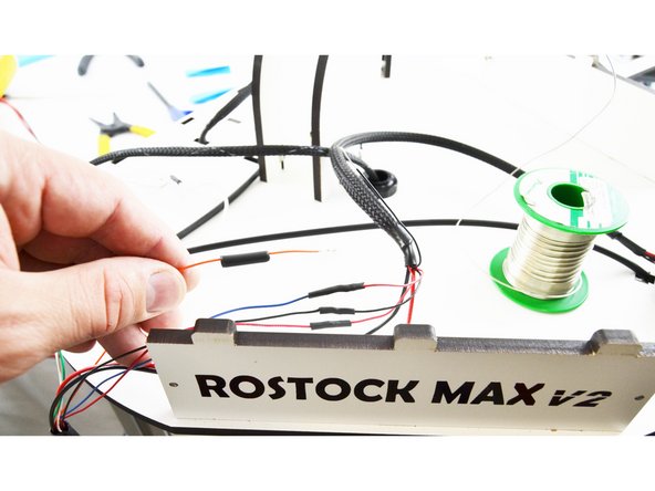
Of the four wires, they will be used for: Layer Fan, PS-ON, and (2) for I2C communication.
-
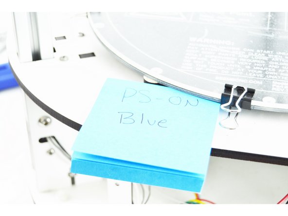
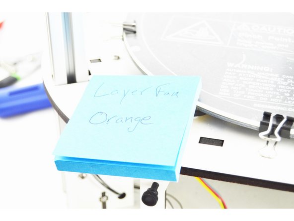
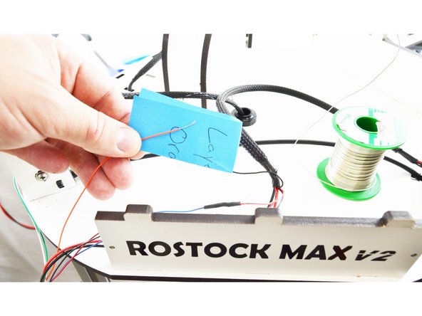
To start determine which of the wires is connected to the Fan 0 - location on the RAMBo board. Use your multimeter for this determination. After you have determined which of the existing wires it is, label the wire Layer Fan/Orange. (I used a post it note shown in step 27 to label the wires)
-
-
-
Determine which of the remaining existing wires is now connected to the blue 26awg wire that is in the 2 pin latching housing. Label it when you have determined it.
-
Finally confirm the final two wires.
-
-
-
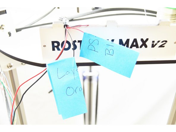
Take a minute and review the wires that you have labeled and ensure that they are correctly labeled.
-
-
-
Match red with red and black with black for the I2C (wires that are in the 4 pin latching housing in thebase of machine, and red / black wires from the new hotend whip)
-
Slide a piece of 15mm long heat-shrink tubing over one of the red wires and one of the black wires.
-
Perform an in-line splice of the wires. Red to red, black to black.
-
-
-
Solder the connections.
-
Slide the heat-shrink up over the connection that you soldered and heat it with a lighter.
-
Do not allow the heat to be concentrated in one place for too long.
-
The heat-shrink will shrink down over the connection.
-
-
-
Locate the wire you labeled as PS-ON. This will go with the blue wire from the new hot end whip.
-
Slide a piece of 15mm long heat-shrink tubing over the blue wire.
-
Perform an in-line splice
-
-
-
Solder the connection.
-
Slide the heat-shrink up over the connection that you soldered and heat it with a lighter.
-
Do not allow the heat to be concentrated in one place for too long.
-
The heat-shrink will shrink down over the connection.
-
-
-
Locate the wire you labeled as Layer Fan. This will go with the Orange wire from the new hot end whip.
-
Slide a piece of 15mm long heat-shrink tubing over the orange wire.
-
Perform an in-line splice
-
-
-
Solder the connection.
-
Slide the heat-shrink up over the connection that you soldered and heat it with a lighter.
-
Do not allow the heat to be concentrated in one place for too long.
-
The heat-shrink will shrink down over the connection.
-
CONGRATS! All 8 wires now have been matched, soldered and covered.
-
-
-
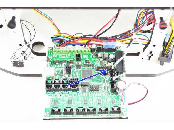
Plug the thermistor wires back into the RAMBo board in the T0 location. This connection is keyed. (shown in the image with a blue arrow)
-
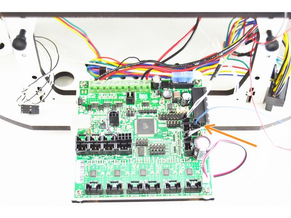
Plug the 2 pin latching housing with the blue wire into the PS-ON location on the RAMBo board. (shown in the image with an orange arrow)
-
-
-
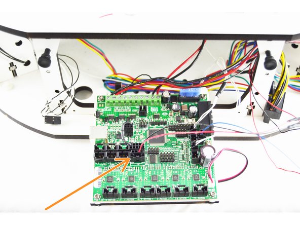
Plug the I2C wires (4 pin latching housing) into the RAMBo board in the I2C location. This connection is keyed. (shown in the image with an orange arrow)
-
-
-
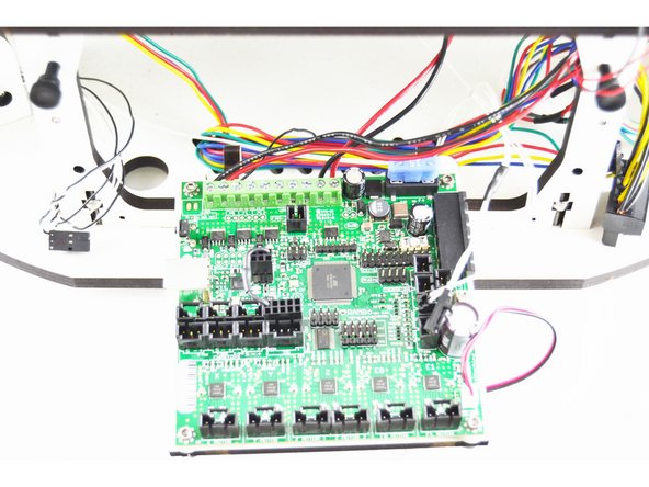
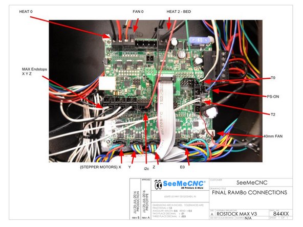
Use the image to the left to perform a final check of your wiring connections. All connections are outlined, and these connections must be made in order for the printer to be functional with the HE280 Hotend.
-
NOTE: You may need to wait to connect the Endstops and Stepper Motors until you have installed the RAMBo in the base of your printer.
-
HE280 power (2 position terminal block with 1 red 18awg & 1 black 18awg wire) goes to Heat 0 terminal ------------- HE280 thermistor (2 position latching connector with 1 white 26awg & 1 green 26awg wire) goes to the T0 position on the RAMBo board
-
Layer Fan power (2 position terminal block with 1 orange 26awg wire (-)) goes to Fan 0
-
Heated bed power (2 Position terminal block with 1 black wire) goes to the Heat2-Bed (-) terminal ---------- Heated bed thermistor (2 position latching connector with 2 white wires) goes to the T2 position on the RAMBo board
-
PS-ON (2 position latching connector with 1 blue 26awg wire) goes to the PS-ON position on the RAMBo board
-
i2c (4 position latching connector with 1 red & 1 black 26awg wire) goes to the i2c position on the RAMBo board
-
Stepper motors connect to stepper motor drivers, labelled X Y Z & E0 ---------- Endstops connect to X Y Z max endstop inputs ---------- 40mm fan connects to 12v AUX output ---------- 12v (6 position terminal block with red and black wires) connects to VIN input on the RAMBo Board
-
-
-
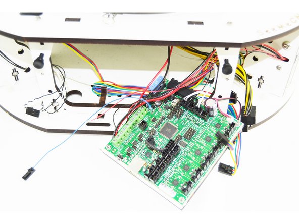
Route the wires around the side of the RAMBo board.
-
Install the RAMBo board back into the printer. Get the top tabs engaged into their slots, and once engaged, pivot the board pushing the bottom of the board into place.
-
-
-
Install the end-stop wires. Be sure that you get XYZ correct (you labeled them). Also, ensure that you install them into the MAX positions on the RAMBo.
-
Install the stepper motor wires. Be sure that you get XYZ Extruder correct (you labeled them). Also, ensure that you install them into the positions on the RAMBo board. The should be: X Y Z _ E0 _
-
-
-
Tame any wires that are protruding from the front of the printer.
-
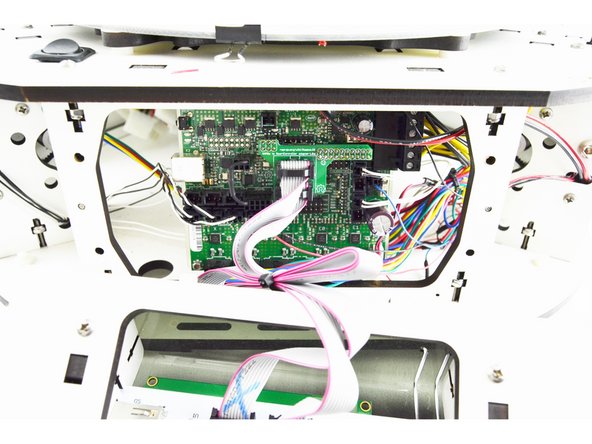
Connect the ribbon cables from the LCD to the RAMBo board.
-
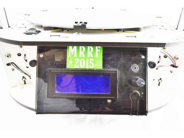
Install the LCD bezel.
-
-
-
If you purchased a fully assembled HE280 Hotend you can continue. If you purchased the hotend as a kit and have not assembled it yet, please perform that assembly now (starting on step 9): HE280 Hotend Assembly
-
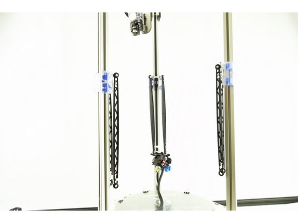
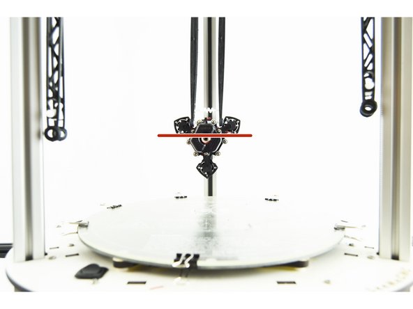
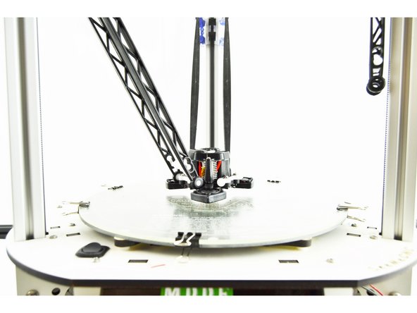
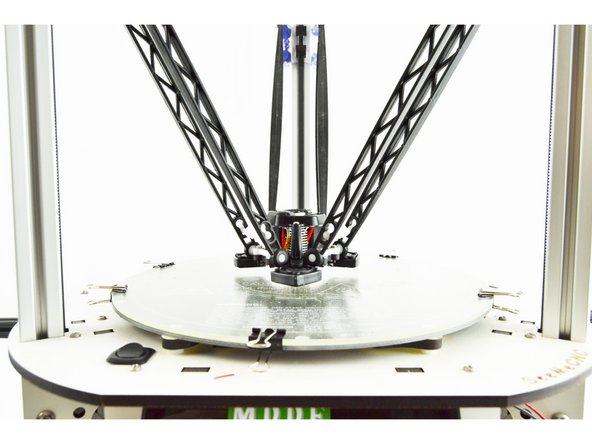
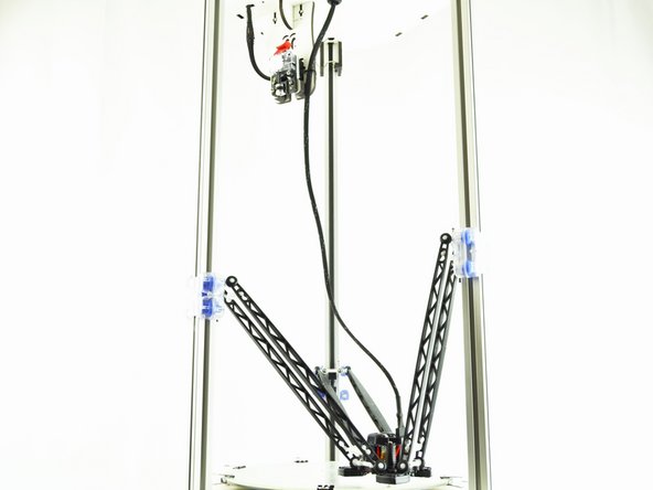
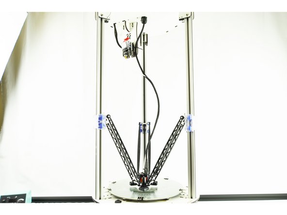
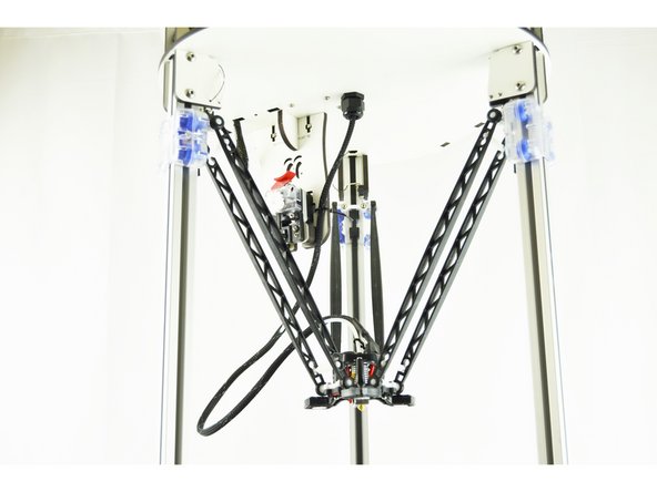
Install the new HE280. Make the ball joint connection on the Z tower/axis first. When correctly installed, and the hot end hanging like in the first picture, you should be able to read "SeeMeCNC" from left to right. This is indicated in the picture with a red line.
-
Connect the arms from the X & Y towers/axis to the hotend platform.
-
-
-
Connect the 8 position pluggable connector to the HE280 Hotend. This plug is keyed. Align the connector and press it into the plug.
-
Bring the hotend/arms down to the height of the bed, (nozzle touching) at the location furthest from the extruder. This location is located to the left of the Y axis tower.
-
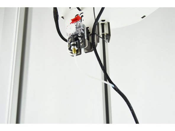
Secure the hotend whip to the extruder mounting panel with a cable tie.
-
-
-
Tame any excess wires in the top of the printer with cable ties.
-
-
-
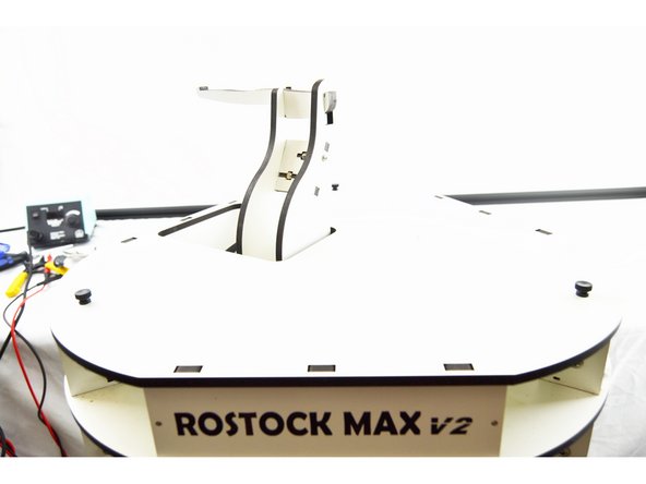
Re-install the top plate of the printer.
-
Secure it with the thumb screws used previously.
-
Install the spool holder arms.
-
-
-
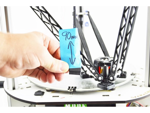
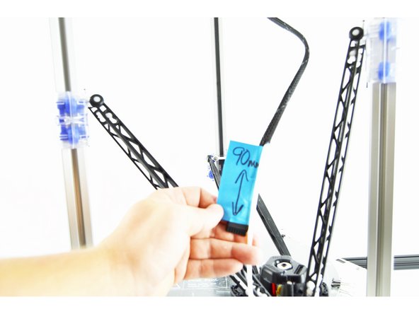
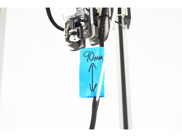
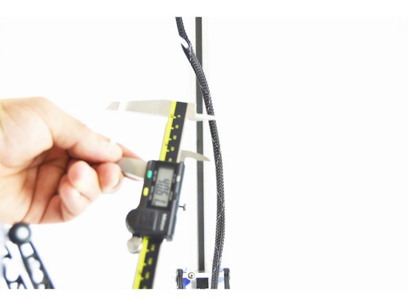
The bowden tube gets installed approximately 90mm from the end of the hot end whip. Measure from the end of the 8 position pluggable connector.
-
You want to insert the bowden tube into the mesh loom on the same side of the connector that has the beveled edges. This is noted in the picture with red makers.
-
-
-
Work the bowden tube up through the mesh loom. It will exit the mesh loom approximately 90mm from the bottom face of the PTC adapter.
-
If you have the EZStruder, that would be 90mm from the end of the brass PTC connector (grey or blue ring).
-
If you have the EZR Struder that would be 90mm from the end of the cartridge PTC adapter (black ring)
-
Keep sliding the bowden tube up through the mesh loom until it is approximately 40mm from the end of the 8 position pluggable connector.
-
-
-
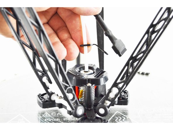
Slide one of the Lanyward PTC Clips onto the Bowden (PTFE) Tube.
-
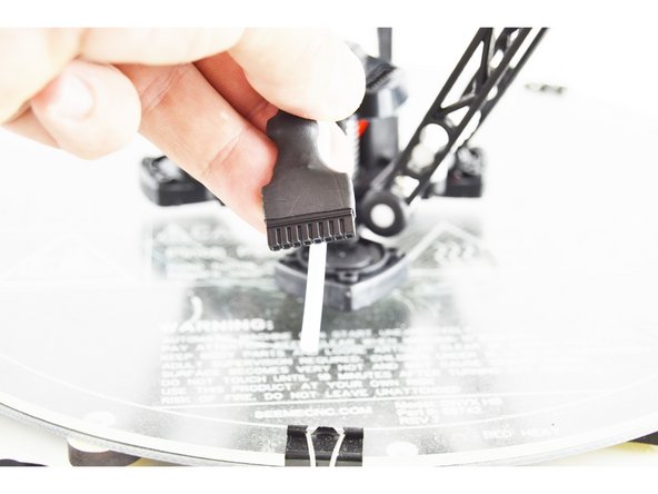
Insert the Bowden (PTFE) Tube into the top of the hot end. Press the tube down until you feel it seat in the bottom of the hot end. Press the hot end effector down so the nozzle is against the glass plate and give the Bowden (PTFE) Tube one more good push to ensure that it is seated fully.
-
With the Bowden (PTFE) Tube pressed down, you will now lift up on the black ring in the top of the hot end.
-
Insert the PTC Lanyard onto the black ring in the top of the hotend. This will secure the Bowden (PTFE) Tube and prevent it from being able to work its way out of the hot end.
-
It is critical that the PTFE is fully seated in the hotend. If it is not it can result in the hot end jamming.
-
-
-
Plug the 8 position plug into the top of the hotend. This plug is keyed on two corners so pay particular attention to the orientation and do not force it if it is not going.
-
-
-
The PTFE tube that is supplied with your upgrade is the length required for the EZR Struder If you have not upgraded to this extruder you will want to trim 40mm off the end of the PTFE tube. end of the PTFE tube.
-
YOU MUST NOT USE SCISSORS. YOU MUST USE A SHARP BLADE SUCH AS A UTILITY OR HOBBY KNIFE.
-
In the pictures for this guide the original EZStruder is being used, therefore the PTFE was trimmed by 40mm.
-
Install the bowden tube into the PTC fitting.
-
-
-
The hardware upgrade is now complete! Great Job!
-
Next you will need to install new firmware on your RAMBo board (after clearing the EEPROM) and learn how to properly use your new HE280 Probing Hotend.
-
We have a How-To Guide for both of the above mentioned items. Be sure when installing firmware, that you choose the machine type that is specific to your printer (Step 8).
-
-
-


Cancel: I did not complete this guide.
8 other people completed this guide.
Attached Documents

11 Comments
anyone have a working config file for simplify3d and the rostock max v2 with this kit installed ?
can not seem to get it calibrated properly
Brian Correll - Resolved on Release Reply
I second the schematic request. Looking at a 49 part tutorial makes it look like this will take 10 hours to complete when it goes much faster. A schematic would let me finnish everything faster.
Also, in step 44, when i mount the HE280 extruder with the bowden tube 90mm from the extruder, the cable for the extruder gets forced out of the plug when i do calibration and printing. As there is no locking connector or any way of securing the cable this is a design fault that definitely need a revision and a switch to a locking connector or other cable tie solution.
Now that the Bowden tube is inserted all the way into the hot end. How do you change filament?
Kevin Feber - Resolved on Release Reply
It would be so much easier for me to just see a schematic of what exists and that it needs to go to. All these steps to cut and jumper are confusing to me.
Albert Einstein - Resolved on Release Reply