
Difficulty
Easy
Steps
8
Time Required
00:45:00
- Carriage Assembly 8 steps

User-Contributed Guide
This guide is not managed by the site's staff.
Quiz
0
-
-
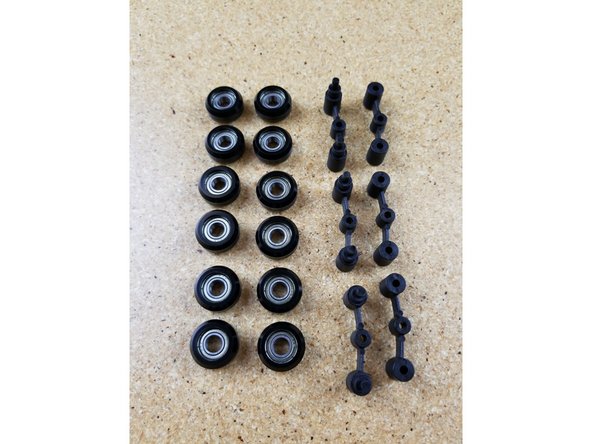
The carriage pack is #70849
-
Its contents are individually bagged as shown.
-
Most of the hardware will be used during this build, pieces that are not, should be placed somewhere safe for installation later, during final assembly of your printer.
-
-
-
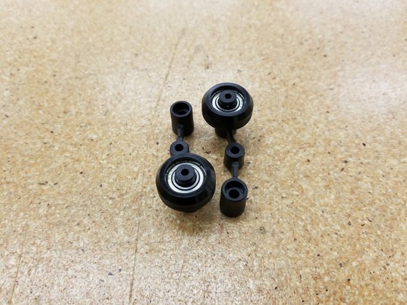
Locate the (12) R4 bearings and (24) black bearing covers.
-
Start by laying a sleeve half on the table, face up. Set an R4 bearing into it and firmly press it into place.
-
Set another sleeve half on the table and press the R4 bearing and sleeve into the new sleeve half to complete the carriage wheel.
-
Note that the sleeves have a sharp edge to them where they were cut free from the bulk stock during manufacture. Take special care not to injure yourself on this edge. It can easily be removed with a razor knife if you so choose.
-
Complete this process for all 12 of the supplied bearings.
-
-
-
If you have the newer style of Spring Arms (implemented summer of 2018) skip to the next step!
-
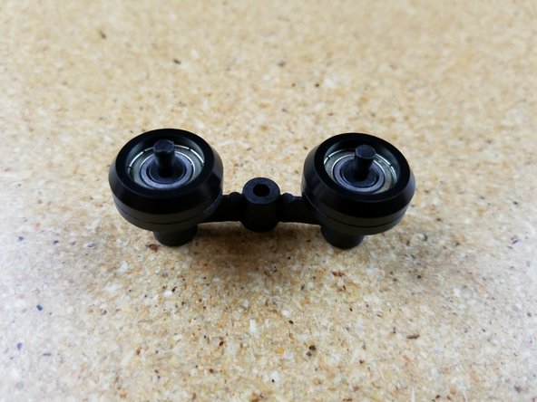
The spring arms consist of an inner and outer halves that retain two of the R4 bearing rollers you assembled in Step #2.
-
Set two R4 bearings on the inner spring arm as shown in photo #2.
-
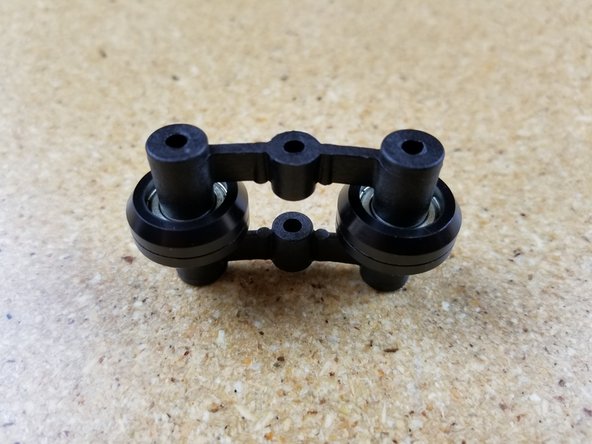
Press fit the outer spring arm on to the two small posts protruding from the inner spring arm. The fit is very tight, but they will fit!
-
In order to fully seat the pins once they're started in the holes, you can tap them in using the back end of your screwdriver as a hammer.
-
Assemble three complete sets.
-
-
-
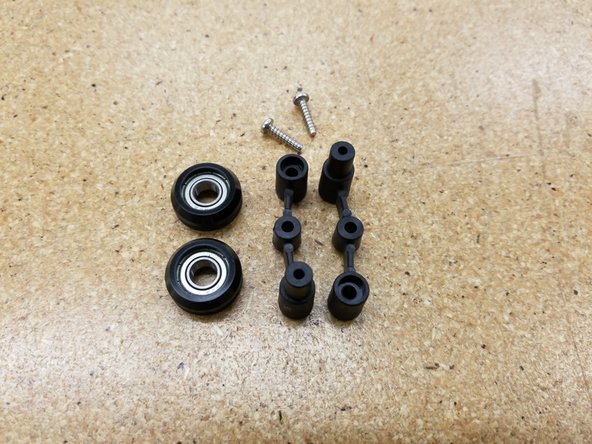
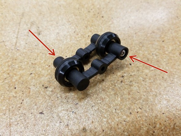
The newer style of spring arms use two identical arms and two screws for assembly.
-
Press the bearings on to the post of either spring arm, as shown in the second photo.
-
Use the supplied 30249 #4 x 1/2" Philips Pan Head sheet metal screws in both sides of the spring arms to secure the bearings in place. Make sure there's no gap and the two halves are fully seated and screwed together.
-
Repeat for all three spring arm assemblies.
-
The remaining steps in this guide show photos of the older style of spring arm, but the orientation and installation is identical between the two styles. You can follow the rest of this guide normally.
-
-
-
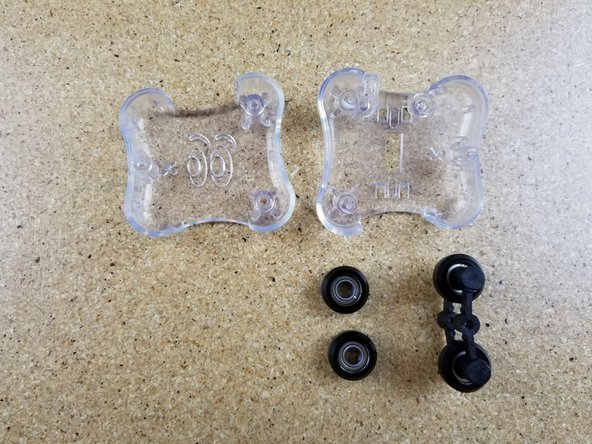
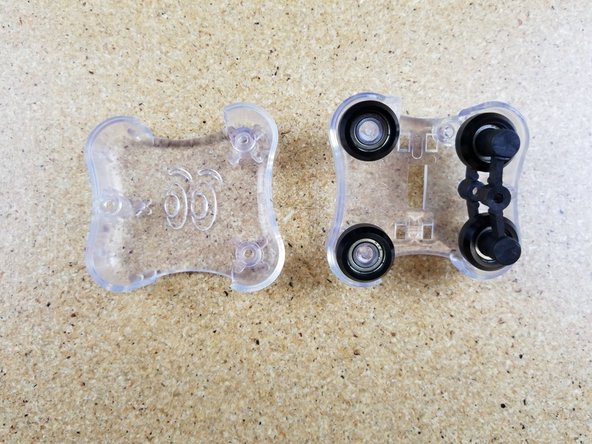
Install two R4 bearing and a spring arm assembly on to an inner carriage half. Make sure you match the spring arm orientation as shown - installing it backwards can damage the spring arms!
-
Install the outer carriage half. Ensure that the alignment pin in that carriage half inserts into the hole in the center of the spring arm.
-
Assemble three complete sets.
-
-
-
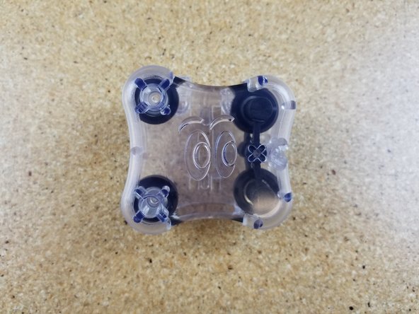
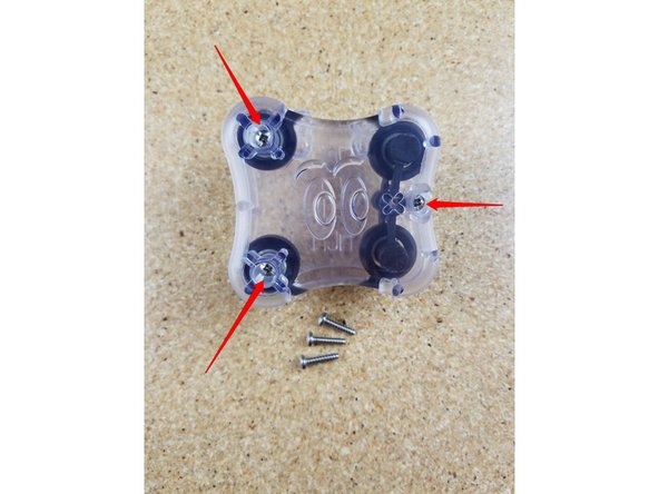
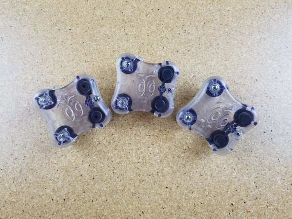
Fix the outer carriage half with the inner carriage half using three #4 x 1/2" sheet metal screws in the locations indicated.
-
Tighten these screws. Do not over-tighten! There is a deliberate 1mm reveal (gap) between the two carriage halves.
-
Assemble three complete sets.
-
-
-
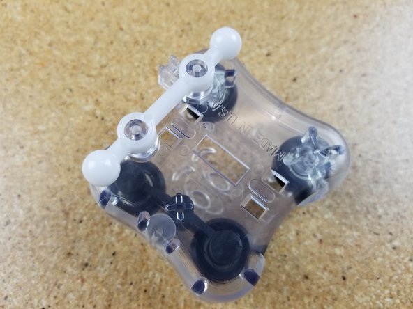
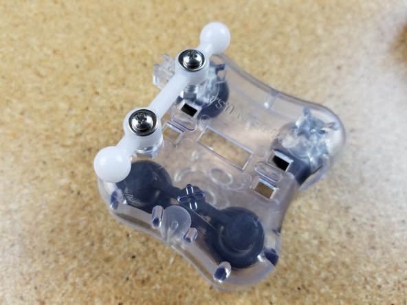
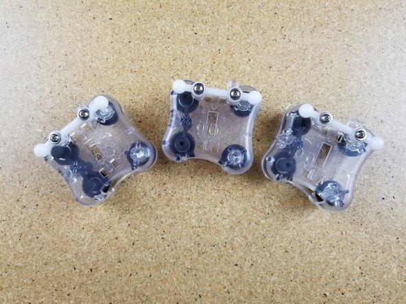
Install the ball joint bars on the mounting pegs as shown.
-
Use two #4 x 1/2" sheet metal screws and two #4 washers to secure the ball joint bar in place.
-
Assemble three complete sets.
-
-
-
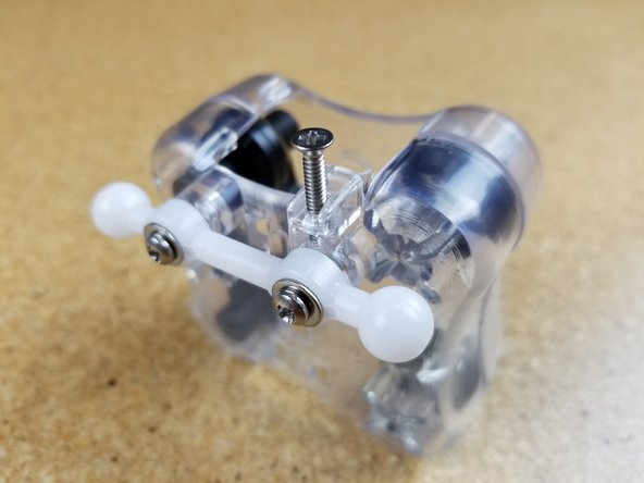
Install the 4/40 3/4" flat head machine screw
-
Stop turning the screw when you feel it has bottomed out! Don't crank it down or you'll strip the plastic!
-
Assemble three complete sets.
-


Cancel: I did not complete this guide.
39 other people completed this guide.

4 Comments
That’s it!? I still have a lot of components left in the bags I had to open to complete these three carriage assemblies.
Graham Goodman - Resolved on Release Reply
A couple of things. All my parts were black. Just know you might get a different color, spent a few frantic moments looking everywhere in the box for blue parts. The little posts on the spring arm in step 3 that you press the other half of the spring arm over had a lot of plastic hanging off the sides. I trimmed that off with a pocket knife, otherwise it wouldn’t fit. I don’t know if it is significant but the assembled spring arms themselves can fit two ways. Either with the holes in the spring arm assembly up or down. I matched what was in the picture for all three.
Adam Ruthford - Resolved on Release Reply