
Introduction
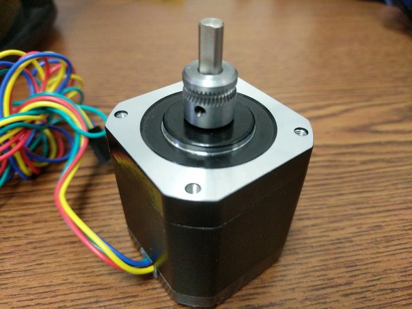
Dual extrusion adapters for single nozzle printing are available now. These kits come complete with everything you need to install on your Rostock MAX v3. New PTFE tubing for BOTH bowden tubes as well as the link between the adapter and the hotend are included as well as a new EZR Struder and NEMA 17 motor.
-
-
If your Y adapter looks like this, use the other guide.
-
Newer 2-into -1 Y adapter guide here Artemis Dual 2 into 1 Installation Guide
-
-
-
Uninstall your stock extruder on the Rostock Max v3 by removing the 4 screws fastening the extruder to the stepper motor.
-
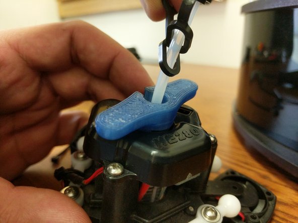
Remove the blue stepper motor knob.
-
Remove the (2) 10-32 screws attaching the side plate to the printer frame.
-
Remove the extruder and side plate from the printer.
-
Remove the (2) 6-32 machine screws and nylon lock nuts fastening the extruder to the extruder motor plate.
-
Make all attempts to keep the extruder together to prevent the spring from becoming sprung.
-
-
-
Align the set screw of the hobbed drive roller with the flat of the stepper motor shaft and install the hobbed drive roller on the stepper motor. Use the existing stepper motor for comparison of placement.
-
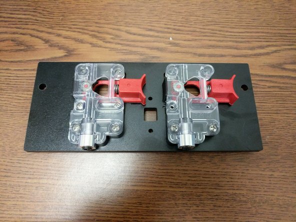
Install the extruder motor assemblies on the extruder plate. Fasten using (2) 6-32 machine screws and nylon lock-nuts for each extruder.
-
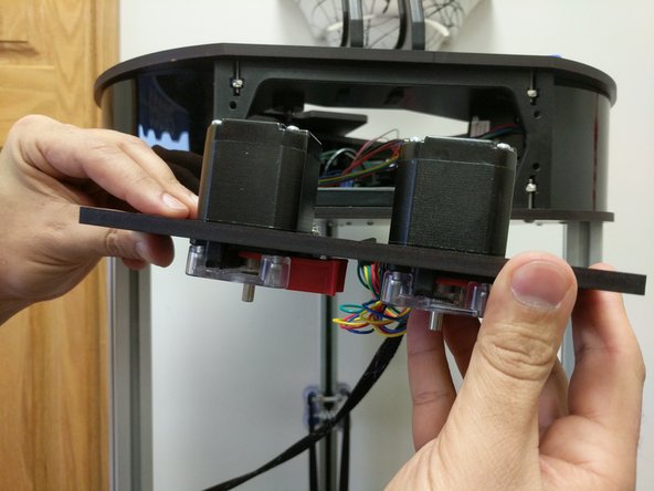
Install the stepper motors on the extruders using (4) M3 screws each. Note that the original extruder stepper motor should be fastened to the T0 extruder (laser etched on extruder plate).
-
Fully tighten all screws.
-
-
-
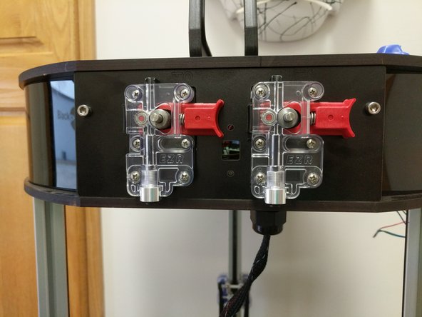
Install the new extruder plate on the side of the machine using the original 10-32 fasteners.
-
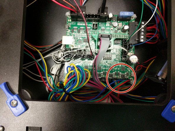
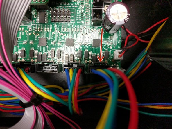
Route the new stepper motor wires as desired in the top frame of the printer.
-
Plug the new stepper motor into the E1 position on the RAMBo board. The original stepper motor should still be plugged into E0.
-
-
-
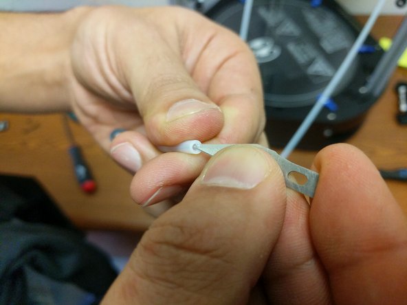
Using a utility or hobby knife blade, carefully cut a 100mm long section of ptfe tubing from the tubing provided. Chamfer one edge of this 100mm long tube. This is the end that goes into the dual feed adapter. The other end of this 100mm section goes down and into the hotend.
-
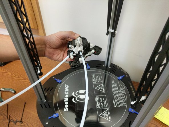
Cut the remaining ptfe tubing in half. Each of these will be the new bowden tubes running from the EZRstruders down to the dual feed adapter. Install the bowden tubes into each of the extruders. Be sure to install the supplied lanyard clips. After installation of the lanyard clip, give the bowden tube a final press up into the extruder assembly.
-
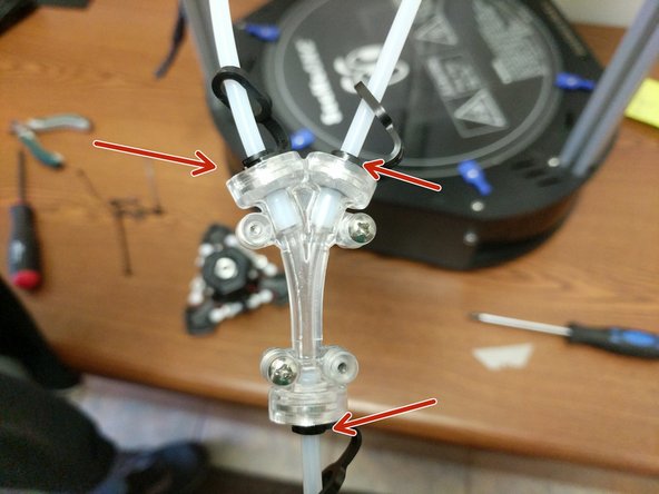
Install the short bowden tube with the chamfered end into the dual adapter on the output (single) side. The chamfered side should be inserted into the dual filament adapter. Install the lanyard clip.
-
Slide lanyard clips onto the 2 long bowden tubes and install them into the dual adapter on the input side. Then clip the lanyard clips in place.
-
-
-
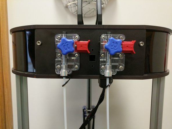
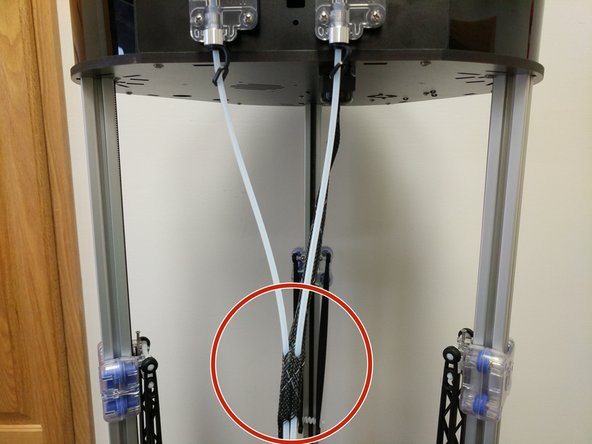
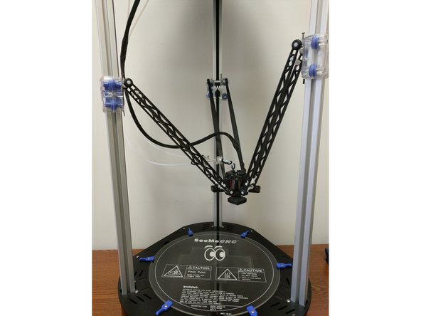
Route the bowden tubes down and run them through approximately 1-2" of the mesh loom as shown.
-
Loosen the PTC adapter in the top of the hot end EXACTLY 2 rotations. (This is the aluminum part on the top of the hot end that has two wrench flats.) You can get this loosened with a pair of need-nose pliers if you do not have a printed PTC tool
-
Loosen the PTC Adapter ONLY 2 Rotations.
-
Slide a lanyard clip onto the bowden tube. Then rest the nozzle down against the build plate (or on a solid surface if the HE280 is removed from the machine)Seat the PTFE tube down in the hotend as far as it can go. Be sure to push hard to get it seated.
-
While maintaining downward pressure on the PTFE tube, tighten the PTC adapter slowly. Ensure that the heat sink, and heater block are not rotating while you are tightening the PTC adapter.
-
The PTC Adapter should tighten 2 full rotations (the amount you loosened it).This will cause the black ring in the top of the PTC adapter to rise up as its teeth engage the PTFE tube.
-
Insert the lanyard clip in the PTC adapter (under the black ring).
-
If you removed the hotend from the arms for the above operation, reinstall it now.
-
-
-
At this time, dual extrusion on SeeMeCNC printers is highly experimental.
-
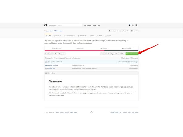
Here is the download: Firmware
-
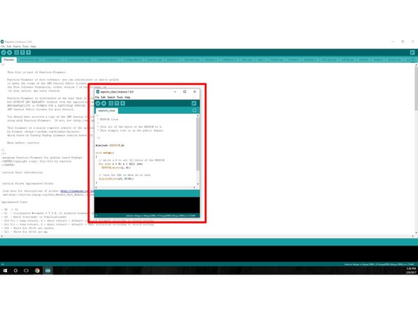
Run an EEPROM Clear Sketch, Located in the Arduino software under File>Examples
-
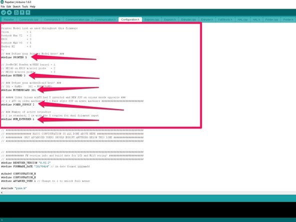
Configure Firmware: Since this is highly experimental at this point in time, the default configuration is pre-equipped for Rostock Max v3. If you are installing this system on a machine other than a Rostock Max v3 you can change configurations here in the configuration.h tab of the firmware.
-
You will need to change the defaults to match your printer model and equipment. FOR DUAL EXTRUSION YOU WILL NEED TO CHANGE THE "#define NUM_EXTRUDER" FROM 1 TO 2
-
Upload the firmware when you are confident that you completed configuration changes.
-
-
-
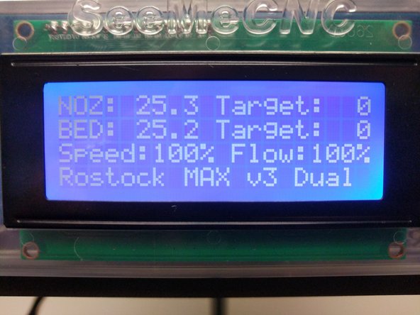
When the firmware has successfully been installed you will see the printer name on the main screen has changed and is now: PrinterModel Dual
-
-
-
The hardware and the firmware are now set up and ready to go! Now its up to you to do some experimenting with your preferred slicing engine to print all things (in dual filaments)
-
We have done beta testing in both MatterControl and Cura with positive results.
-
Note to users: T0 is the original extruder, T1 is the new extruder. Issuing T0/T1 will switch to that extruder and make it active.
-


Cancel: I did not complete this guide.
One other person completed this guide.

6 Comments
there is no black ring at the bottom of the Y attachment. There is a metal screw with a bolt that kind of looks like the one on the top of the hot end. I don’t see how to install the 100mm tube in it securely. It just slides out.
Carol McCullough-Dieter - Resolved on Release Reply
How do you enable the dual extrusion setting in MatterControl? I'm failing to figure out how to make my MatterControl screen look like the one pictured above.
Jordan Miller - Resolved on Release Reply
I'm confused about the PTFE tubing. Does it need to be a specific length? Do the lengths of tubing coming from the extruders need to be similar?
CorranThorn - Resolved on Release Reply