-
-
SEE REV B ASSEMBLY IF YOU PURCHASED AFTER MAY 23, 2018
-
If you purchased AFTER May 23rd, please see other assembly guide.
-
-
-
If your touchscreen kit does not look like the picture, STOP! And LOOK for the newer MAY2018 UPDATE.
-
NOTE: This guide is intended to be followed online in order to fully utilize the links and documentation found within.
-
First, click here to read safety information . This safety information may be updated at anytime so occasionally check for updates.
-
Open and inspect the contents of your touch screen kit to ensure you have all the parts listed on the BOM.
-
Begin by peeling the protective transfer tape from the laser cut wood panels.
-
You will need to 3D print the bezel for the screen, so you may wish to do that before getting started with the installation. You can get the files for the bezel from here: 5 INCH TOUCH SCREEN CONTROLLER KIT FOR V3.2. You will need to print both the front and the back bezel parts.
-
-
-
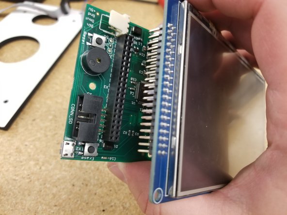
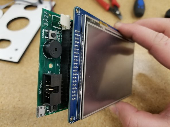
Install the PanelDue control board on the touch screen as shown. Be sure the pins all align and plug in fully.
-
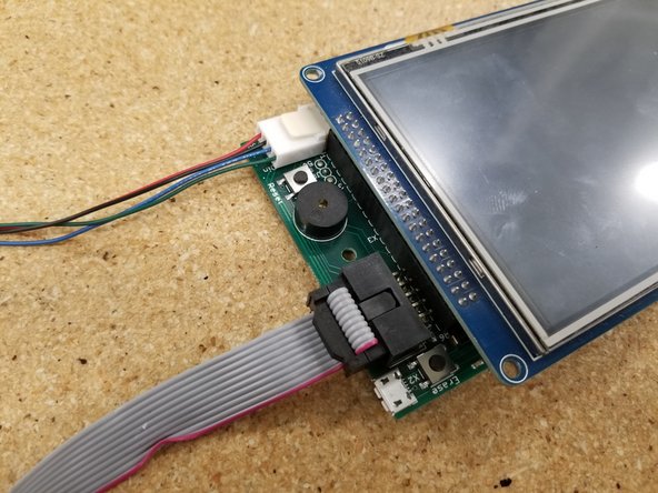
Plug in the two cables as pictured. Make sure the green wire on the molex connector is oriented towards the ribbon cable, and the red wire on the ribbon cable is oriented towards the "Erase" button.
-
Both the ribbon cable and the molex cable should only install one direction as they are keyed.
-
-
-
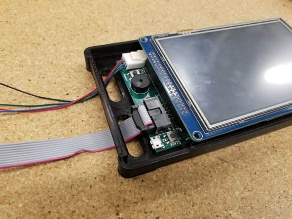
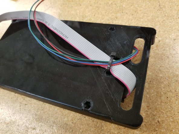
Pass the cables through the holes in the back plate of the bezel you printed earlier.
-
Affix them with a zip tie as shown. You do not need to crank down the zip tie, be more kind to that ribbon cable than the photo shows...
-
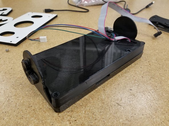
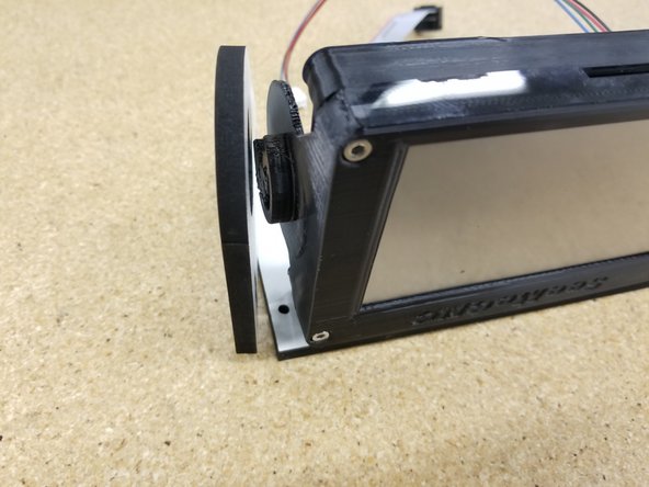
Align the two halves of the bezel enclosure, making sure that the SD card notch on the front enclosure half is aligned with the SD card slot on the screen.
-
-
-
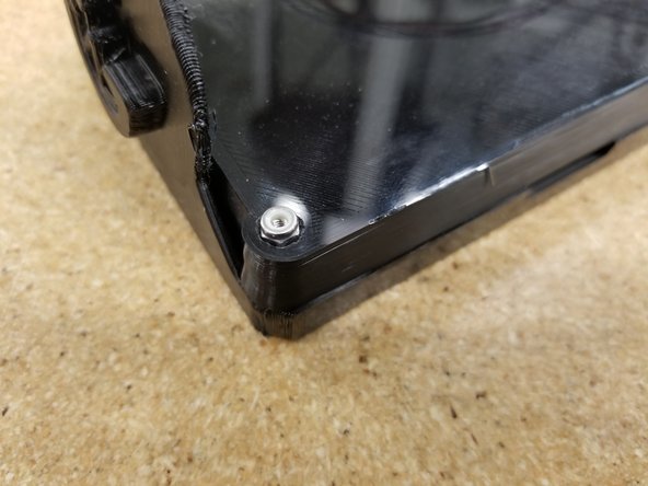
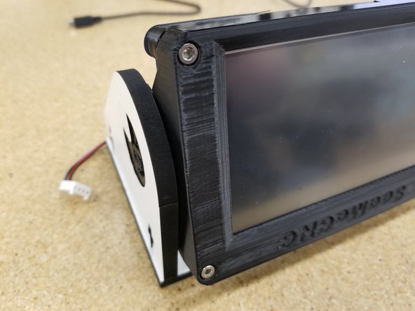
Use the M3 Nylon Lock nuts and the M3 22mm SHCS bolts to combine the two halves of the bezel.
-
The bolts should pass through the holes on the PCB of the touch screen when everything has been aligned properly.
-
-
-
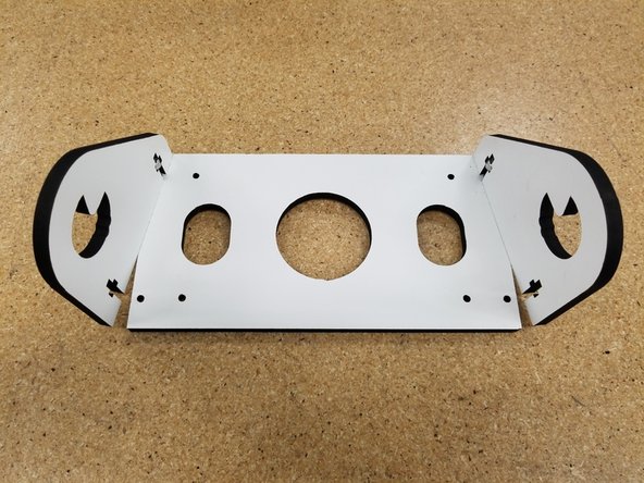
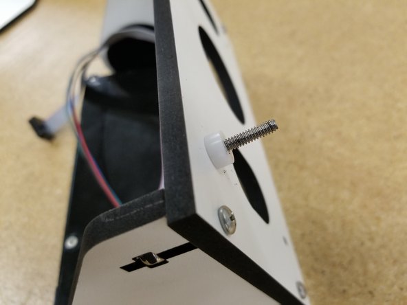
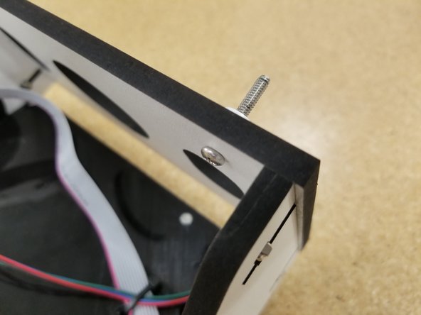
Insert the 6-32 nylon lock nuts in the laser cut side panels and insert the 6-32 1" machine screws in the shorter end of the panel as seen in the photo. Don't tighten these all the way, keep them somewhat loose for what's to come.
-
Rotate the panels out as shown in the photo.
-
-
-
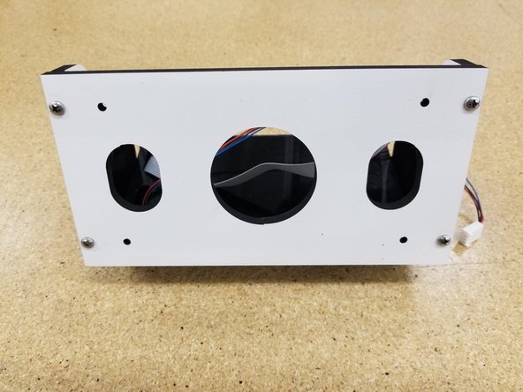
Align the printed enclosure to where it will be sitting in the side panels, with the SD card slot facing away from the main mounting plate.
-
Rotate the side panels inward and press both halves together around the printed enclosure.
-
You can now insert the second set of 6-32 1" machine screws and tighten all four down.
-
-
-
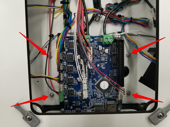
Install the touch screen assembly to the bottom plate of your top assembly using the 6-32 1" machine screws, plastic bearings, and 6-32 nylon lock nuts.
-
The mount will install in the pre-cut holes shown by the arrows.
-
-
-
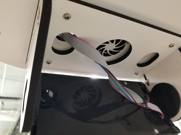
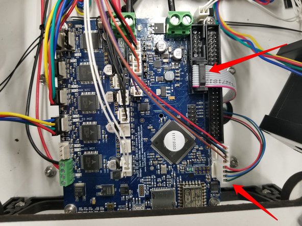
Route the cables through the pre-cut hole as shown.
-
Plug the cables into the indicated locations on the Duet.
-
Both the ribbon cable and the molex cable should only install one direction as they are keyed.
-
-
-
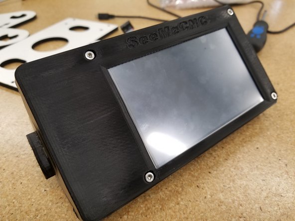
Reinstall any covers you may have removed from the machine during this installation, and power your machine back on.
-
Enjoy your new touch screen display!
-