
Difficulty
Moderate
Steps
5
Time Required
- LCD Enclosure 5 steps

User-Contributed Guide
This guide is not managed by the site's staff.
Quiz
0
-
-
Locate the LCD pack of parts from your kit or order.
-
If your kit / printer is equipped with a RAMBo board you will have a RAMBo / LCD Adapter Board in your kit this is identified in the 3rd picture. This adapteer board is not required when using the LCD with Mini-RAMBo boards.
-
-
-
Remove the protective label from the Piezo buzzer
-
Remove the knob from the Rotary Encoder. This is a compression fit and removes by simply pulling it off.
-
-
-
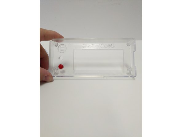
Insert the red button in the enclosure front (from the inside). The flange on the button will prevent it from falling all the way through.
-
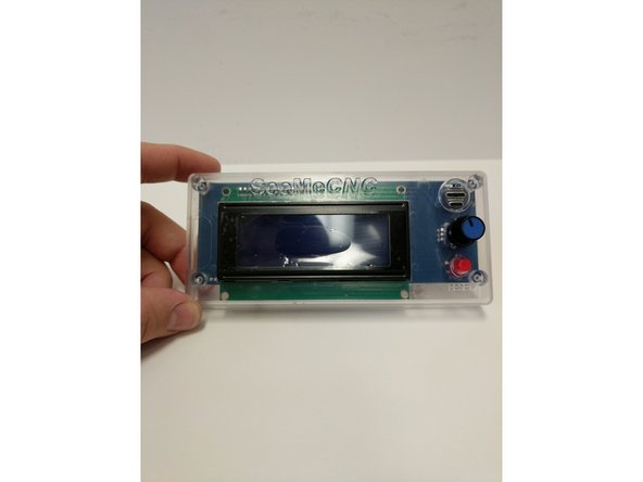
Insert the LCD controller into the enclosure front case. The SD card reader on the right side will line up with the recess in the enclosure.
-
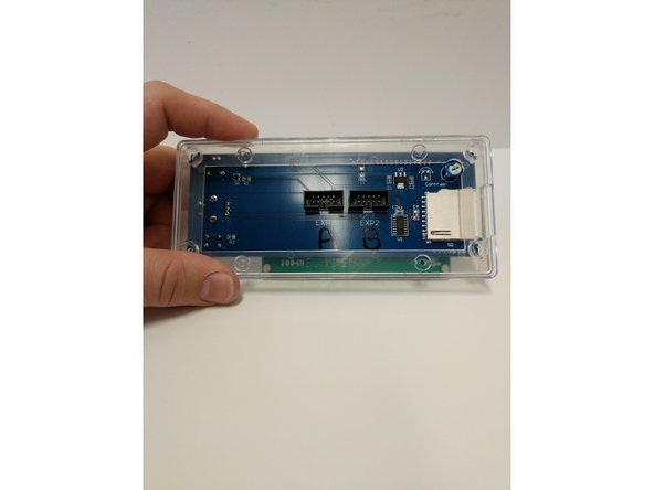
Insert the LCD enclosure back over the controller. This component has a boss that will line up with the SD card reader.
-
-
-
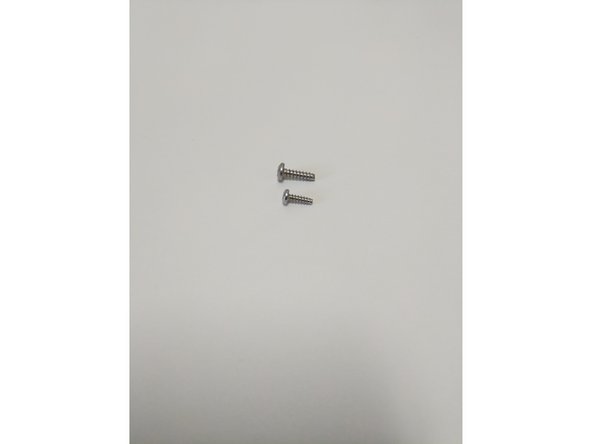
There are two sizes of sheet metal screws (#4 x 3/8" & #6 x 1/2") in your LCD enclosure pack (shown in image 1)
-
The smaller (#4 Sheet Metal Screw) will be used on the four outtermost corners of the enclosure. These screws will go through the Back Cover Piece, Controller and then self tap into the Front Cover Piece.
-
Tighten the (4) screws.
-
Do not Over-Tighten causing the plastic enclosure to be damaged.
-
Insert the (4) larger sheet metal screws (#6 x 1/2") into the inner holes in the back of the enclosure. Screw these in 2 rotations. They will be fastened to other components later, this is being done now to prevent losing them.
-
-
-
Insert the knob back onto the Rotary Encoder.
-
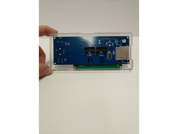
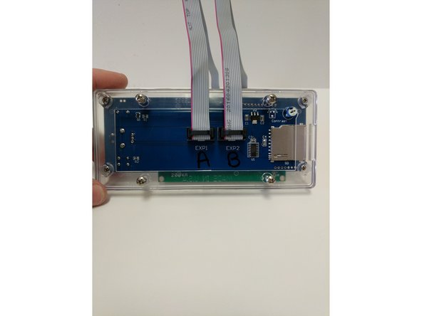
Install the Ribbon cables in the connectors on the back of the LCD Controller. These connections are Keyed.
-
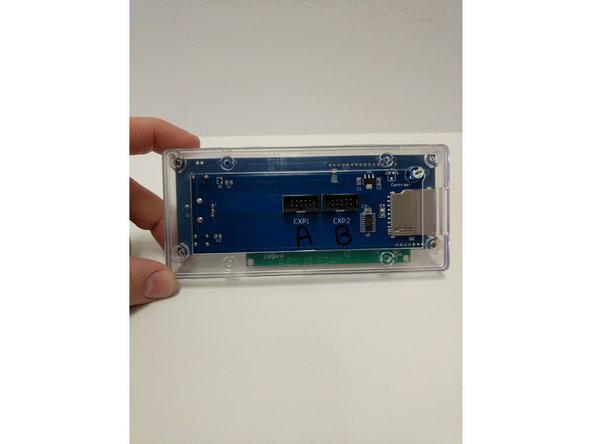
The connectors on the back of the LCD Controller are labeled EXP 1 & EXP 2. Label EXP 1 with an A and label EXP 2 with a B. Then label both the ends of the Ribbon Cables with A & B.
-
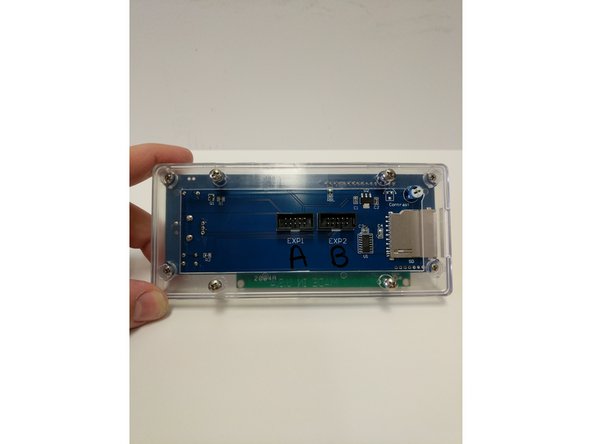
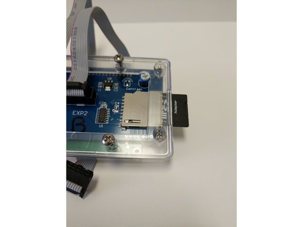
Remove the SD Card from the packaging. Insert the Micro SD card into the SD Card Adapter. Insert the SD card into the SD Card Reader in the LCD Controller.
-
The text on the SD card will face the back of the LCD Controller
-


Cancel: I did not complete this guide.
24 other people completed this guide.

2 Comments
Two comments. Don’t forget to remove the white paper cover from the buzzer on the front of the controller, it says to do so it is just easy to overlook. Also, I have a leftover part from this step. It is a small triangular shaped circuit boar with two male pin connectors on one side and three female pin connectors on the other.
Adam Ruthford - Resolved on Release Reply