
-
-
First, click here to read safety information . This safety information may be updated at anytime so occasionally check for updates.
-
NOTE: This guide is intended to be followed online in order to fully utilize the links and documentation found within.
-
Open and inspect the contents of your touch screen kit to ensure you have all the parts listed on the BOM.
-
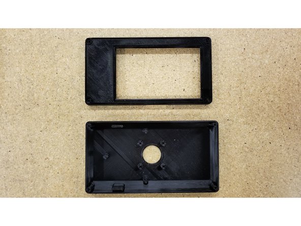
If you did not purchase the optional enclosure parts add-on, you will need to 3D print the enclosure parts, click the following to download:
-
click to download front cover
-
click to download back enclosure
-
click to download case post
-
click to download frame post
-
-
-
Note: We no longer ship with the 4 pin connector as it is no longer needed! Only the ribbon cable is used!
-
Orient the cables as shown. With the alignment tabs from both connectors facing upwards, the red wires should be oriented away from each other.
-
Pass both cables through the mesh loom. You will need to expand the mesh loom as much as possible in small increments to pass the large connectors through.
-
-
-
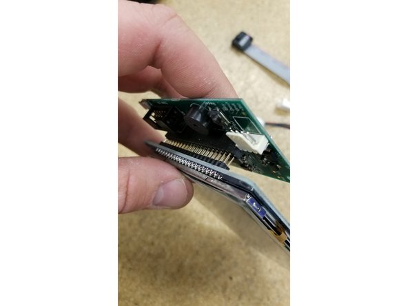
Install the PanelDue control board on the touch screen as shown. Be sure the pins all align and plug in fully.
-
Plug in the two cables as pictured. Make sure the green wire on the molex connector is oriented towards the ribbon cable, and the red wire on the ribbon cable is oriented towards the "Erase" button.
-
-
-
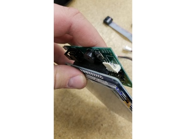
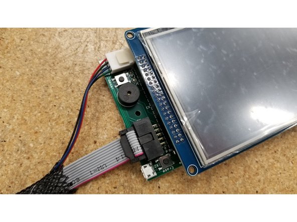
Plug in the two cables as pictured. Make sure the green wire on the molex connector is oriented towards the ribbon cable, and the red wire on the ribbon cable is oriented towards the "Erase" button.
-
Both the ribbon cable and the molex cable should only install one direction as they are keyed.
-
4 Pin molex connector no longer used, only use ribbon cable.
-
-
-
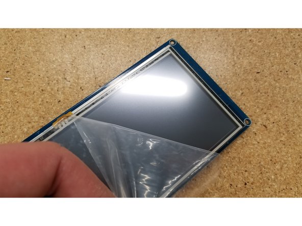
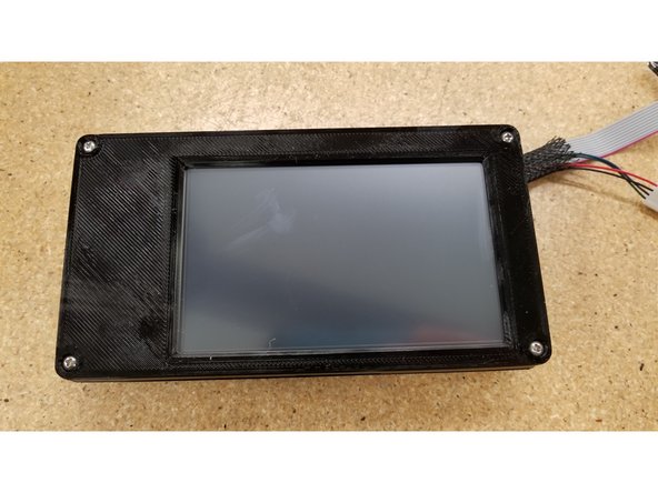
Peel the film off the touch screen.
-
Make sure to enjoy the satisfying feeling of peeling the film off new electronics. Yeah...that's nice.
-
Locate the front and back half of the screen enclosure for the following steps.
-
-
-
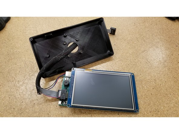
Pass the cables through the hole in the back of the enclosure, and insert the screen as shown.
-
Be sure that the back enclosure half is oriented as seen in the photo, using the board standoff posts as a reference point.
-
-
-
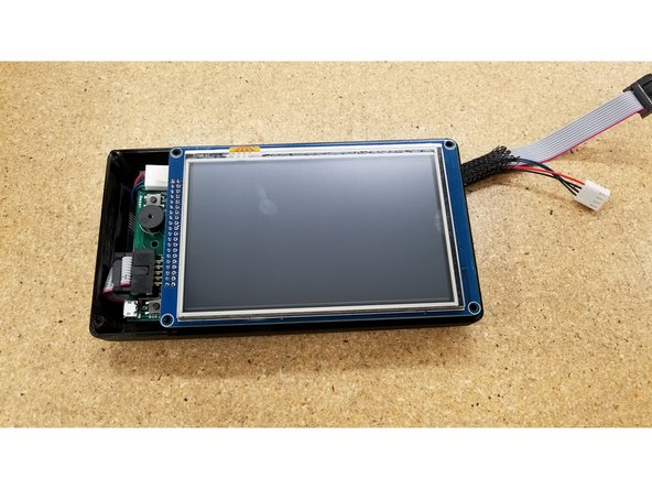
Align the front half of the screen enclosure as seen.
-
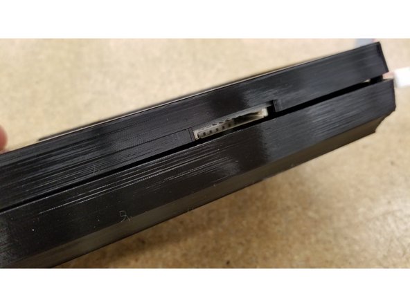
Make sure the opening for the SD card lines up with the SD card slot at the bottom of the screen.
-
Secure the two enclosure halves together using the four #4 1/2" L sheet metal screws
-
-
-
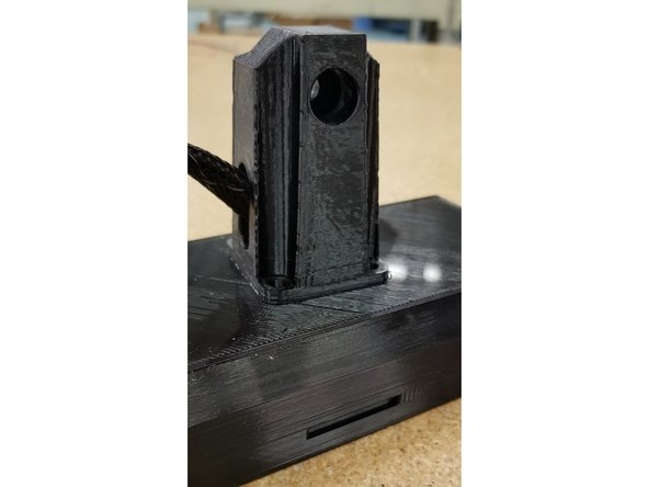
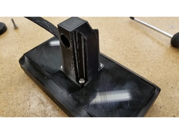
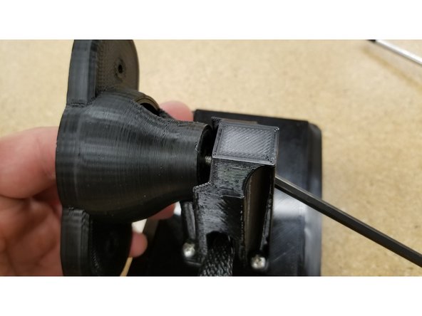
Locate the screen mounting arm and pass the cables through as shown.
-
Position the arm on the enclosure as shown, ensuring the flat side with the bolt hole is aligned with the bottom of the screen (indicated by the SD card slot)
-
Secure the post in place using the four #6 1/2" L sheet metal screws
-
-
-
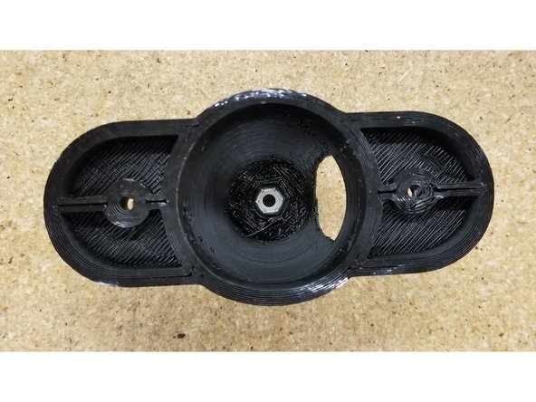
Make sure the 10-32 nylon lock nut is seated in the arm post as shown.
-
Use the 10-32 x 3/4" L SHCS and the #8 SAE flat washer to secure the two arm parts together as shown.
-
-
-
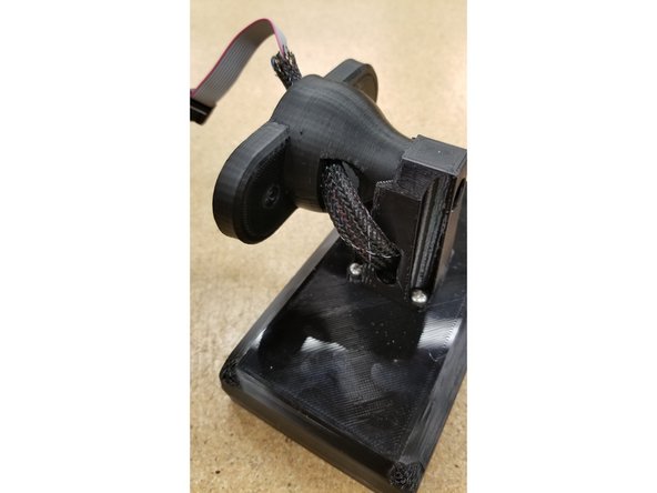
Pass the cables through the screen arm assembly as shown.
-
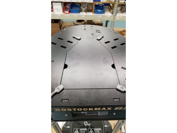
Open the top hatch on your printer.
-
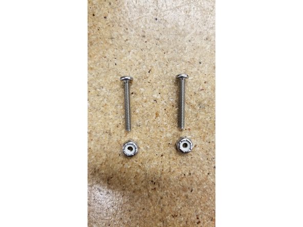
Locate the two 6-32 nylon lock nuts and 1" L machine screws.
-
-
-
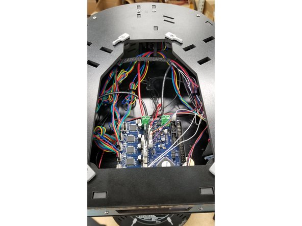
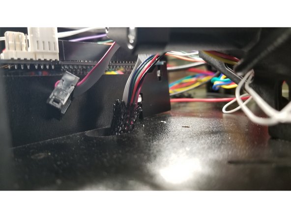
Pass the cables through the hole to the right of the Duet board.
-
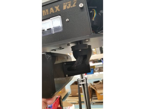
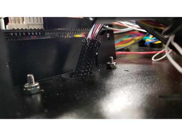
Pass the 6-32 x 1" machine screws through the touch screen arm assembly and the holes next to the Duet board as shown, and secure the screen assembly in place with the 6-32 nylon lock nuts.
-
-
-
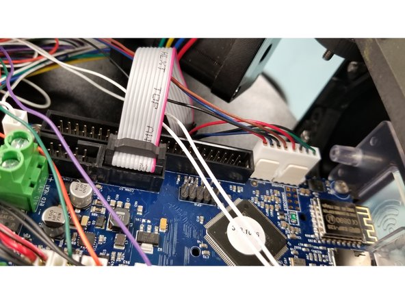
Plug the cables into the Duet board as shown, and replace the top hatch on your printer.
-
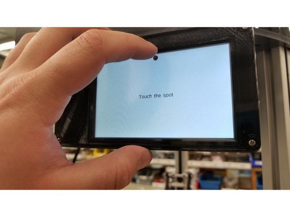
Turn the machine on, and touch the dots to calibrate the screen.
-
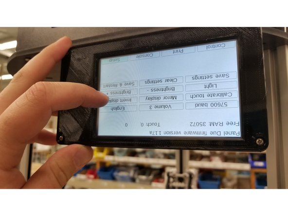
The screen should be inverted from the factory. We will change this setting in the next step.
-
-
-
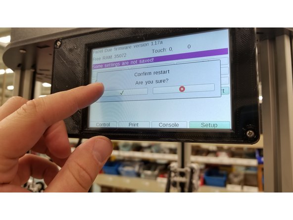
Select "Setup" > "Invert Display"
-
Re-calibrate the screen by touching the dots.
-
-
-
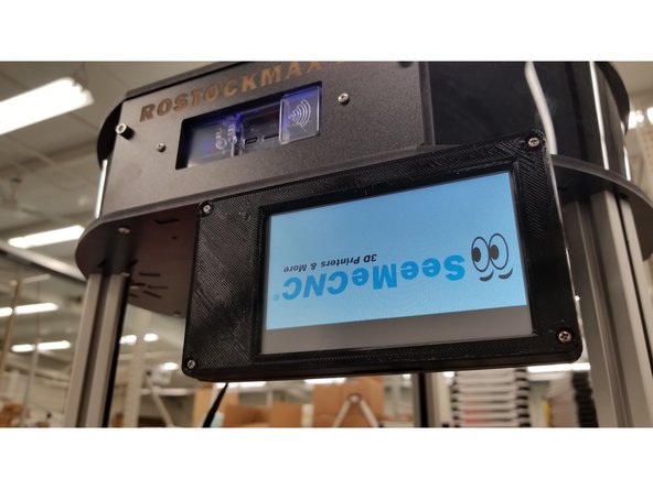
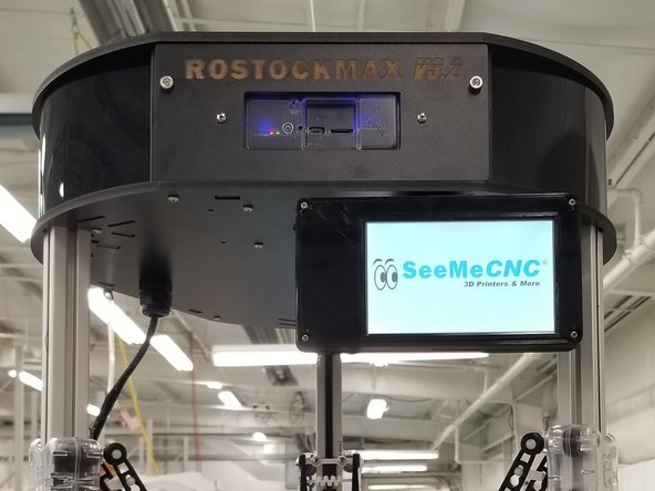
Enjoy your new touch screen!
-
Be sure not to rotate the screen too far to the right, as it could pinch and possibly damage the cables. Future versions of the arm design have a rotation limiting post to prevent this from happening.
-


Cancel: I did not complete this guide.
One other person completed this guide.
One Comment
Good description of the actions needed. Per haps additional, there is a possibility to update the firmware inside the PanelDue.
All information can be found through this link: https://miscsolutions.wordpress.com/pane...