Difficulty
Moderate
Steps
7
Time Required
- Droplit v2 Carriage Assembly 7 steps

User-Contributed Guide
This guide is not managed by the site's staff.
Quiz
0
Tools
Parts
-
-
The hardware for this assembly is located in the bag labeled 78896 Droplit v2 Carriage Assembly
-
Go ahead and locate that hardware now.
-
-
-
Locate the (4) R4 Bearings and (8) Bearing Covers.
-
Start by laying a sleeve half on the table, face up. Set an R4ZZ bearing into it and firmly press it into place.
-
Now set another sleeve half on the table and press the R4ZZ bearing and sleeve into the new sleeve half to complete the carriage wheel.
-
Repeat this process for the (3) remaining bearings.
-
-
-
-
Locate the Inner and Outer Spring Arms, shown in the animation.
-
The spring arm is easy to assemble, but the small posts are a very tight fit, so be careful when assembling them. Note that each arm half has an “inside” and “outside” to it.
-
Slide two sleeved R4ZZ bearings on to the outer spring arm posts as shown.
-
Next, press the inner spring arm on to the two mating posts that are on the outer spring arm. (Ensure the curvature of the spring arms are in the same orientation)
-
This is a very tight fit. You can get each side started by aligning the holes in the inner spring arm over the posts in the outer spring arm and then tap them into place with the handle of your P2 screwdriver. You want the pins fully seated.
-
Install the remaining two bearing with sleeves onto the R4 Bearing Bushing Block. There are 3 posts for bearings. You will be installing the bearing on the top and bottom posts. The middle post will be left empty.
-
-
-
-
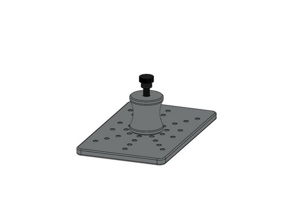
Locate the Carriage Mounting Plate, M10 Anti-BackLash Nut, 10-32 Knurled Thumb Screw, (3) #4 Pan Head Phillips Screws, and (3)#4 Washers.
-
NOTE: You should have tapped the 2 holes in the carriage mounting plate as part of the Preparing For the Build Steps. If you have not done that yet, please do so now.
-
The Carriage Mounting Plate is symetrical, so it does not matter which side you attach the Anti-Backlash nut to, so long as the orientation from the animation is kept in regards to the Anti-Backlash nut and the Knurled Thumb Screw
-
The #4 Pan Head screws will self tap into the Anti-Backlash nut. At this time, you should NOT fully tighten these screws.
-
You can however fully tighten the Knurled Thumb Screw.
-
-
-
-
Locate the (2) Carriage Side Plates, Spring Arm assembly put together in step 2, (2) R4 Bearings with covers, Bearing Bushing 3/4 Position, (3) 6-32 x 2" Phillips Flat Head Screws, (3) 6-32 Nylon Lock Nuts, (7) #6 Washers, and (2) Plastic Bearings, and (1) 6-32 x 1/2" Socket Head Cap Screw.
-
The Carriage Side Plates are symmetrical, therefore left/right can be interchanged.
-
Orient the components are shown in the animation. The 6-32 x 1/2" Socket Head Cap Screw should be the last item installed to ensure that is placed in the correct location (back left side). This screw be secured with a 6-32 Nylon Lock Nut (not shown in the animation).
-
NOTE: The Spring Arms can be installed in either orientation, But when it comes time to install the Carriage on the TSLOT the Spring Arm must be in such a way that the bearings are closer to the TSLOT than the pivot point.
-
You should fully tighten the (2) 6-32 x 2" screws that attach the sides to the Bearing Bushing 3/4 Position.
-
Tighten the 6-32 x 2" screw that passes through the Spring Arms with 1/2 turn increments. You want the Spring Arms to be secured, but you still want them to be able to pivot. If you find that you have over tightened this screw and the Spring Arms no longer can pivot, back the screw out slightly until they can pivot again.
-
-
-
-
Locate the (4) 6-32 x 1" Phillip Pan Head Screws, 6-32 Nylon Lock Nuts, Carriage Mounting Plate assembly, and Carriage Side Plate assembly.
-
Join the Carriage Mounting Plate assembly, and Carriage Side Plate assembly together using the supplied hardware noted above.
-
Fully tighten the (4) 6-32 Phillips Pan Head Screws
-
Leave the (3) #4 Pan Head Screws attached to the Anti-Backlash nut loose for now. Those will be tightened at a later point.
-
-