-
-
We're working on the final revision.
-
Assemble your FRS unit. If you are using printed parts for the housing and cover, ensure that they fit together well.
-
Be sure the bearing rotates freely without interference from any printed protrusions.
-
Be sure the filament guide protrusions fit together well and provide a clear filament path free of obstructions.
-
DO NOT drop the ball bearing. (you will never find it again)
-
When everything is good, do your final assembly with two screws.
-
-
-
FIRST: Unplug your printer from the AC line voltage. Risk of electric shock!
-
Remove the cover(s) to access the Duet controller.
-
Plug one end of the KK wire harness into the E0 (and E1 if installing both) end stop switch header(s) of the Duet controller.
-
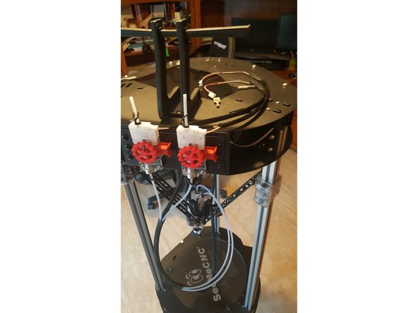
Route the wire harness to the extruder.
-
Re-install protective covers so no AC line voltage is exposed so the printer is safe for operation.
-
-
-
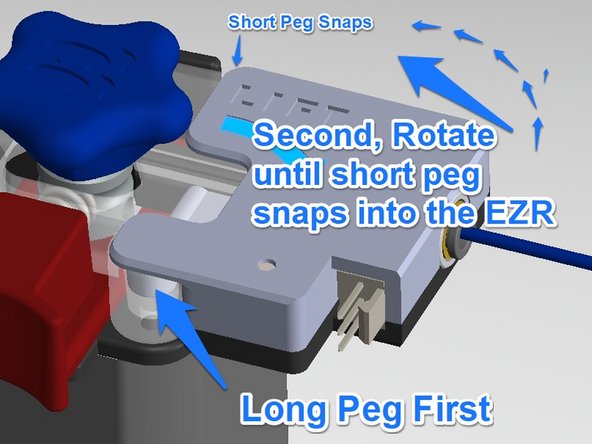
It's a snap, really. No tools required.
-
Just insert long peg, rotate and gently lift, and snap short peg into hole.
-
Plug in wiring connection.
-
-
-
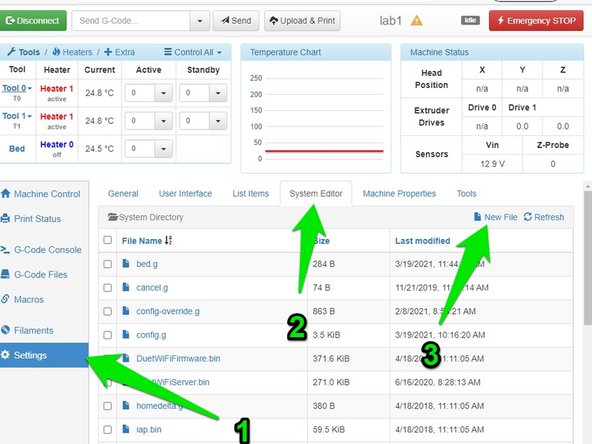
Go to the Duet control screen: go to "Settings", then "System Editor" then click "New File" <<SEE PICTURE>>
-
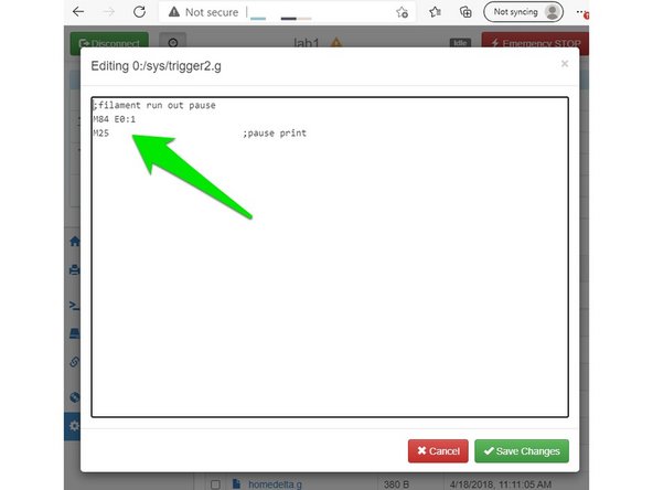
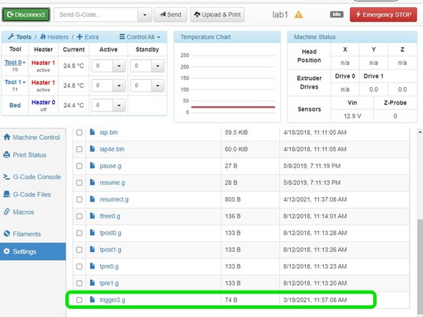
Name the new file (no quotes) "trigger2.g"
-
Enter 2 lines of code as follows and save: <<SEE PICTURE>>
-
M84 E0:1
-
M25
-
And the sys folder will show the new file. <<SEE PICTURE>>
-
-
-
Open the system folders.
-
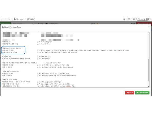
CLICK on "config.g" file to open and edit.
-
Don't be concerned if your config.g file looks a little different from the picture. Don't change your file. Just add to it.
-
Add the new lines below comments for the hotend fan. The new lines are shown in the photo and below, then save
-
M591 D0 P2 C3
-
M581 E0:1 S0 T2 C0
-
Power cycle your printer.
-