
-
-
First, click here to read safety information . This safety information may be updated at anytime so occasionally check for updates.
-
NOTE: This guide is intended to be followed online in order to fully utilize the links and documentation found within.
-
Open and inspect the contents of your touch screen kit to ensure you have all the parts listed on the BOM.
-
If you did not purchase the optional enclosure parts add-on, you will need to 3D print the enclosure parts, click the following to download:
-
click to download front cover
-
click to download back enclosure
-
click to download case saddle post
-
click to download saddle clamp
-
-
-
Please note that the 4 pin molex connector is no longer included with the kit. Only use the ribbon cable as the 4 pin cable is no longer used.
-
Orient the cables as shown. With the alignment tabs from both connectors facing upwards, the red wires should be oriented away from each other.
-
Pass both cables through the mesh loom. You will need to expand the mesh loom as much as possible in small increments to pass the large connectors through.
-
Lightly sanding or filing off the sharp corners of the large connector going through the mesh loom will help this step. Insert the ribbon cable first, then the white connector cable.
-
-
-
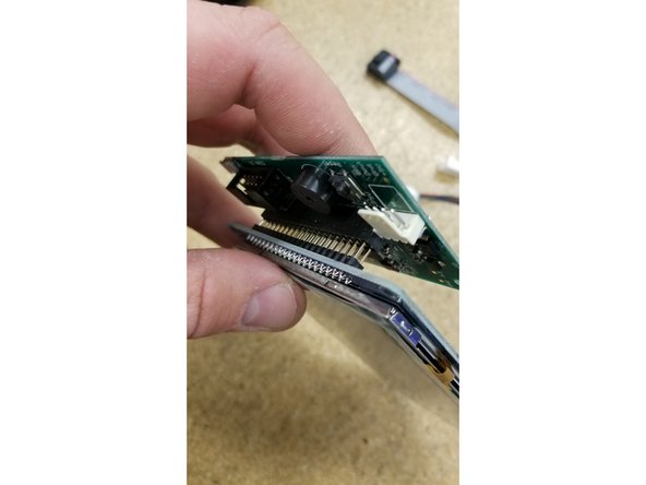
Install the PanelDue control board on the touch screen as shown. Be sure the pins all align and plug in fully.
-
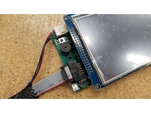
Plug in the two cables as pictured. Make sure the green wire on the molex connector is oriented towards the ribbon cable, and the red wire on the ribbon cable is oriented towards the "Erase" button.
-
-
-
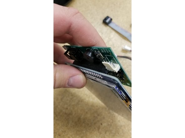
Plug in the two cables as pictured. Make sure the green wire on the molex connector is oriented towards the ribbon cable, and the red wire on the ribbon cable is oriented towards the "Erase" button.
-
Both the ribbon cable and the molex cable should only install one direction as they are keyed.
-
Again, the 4 pin molex is not used or included. Only use the ribbon cable.
-
-
-
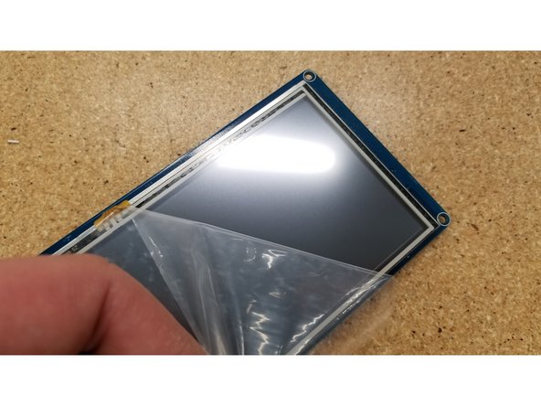
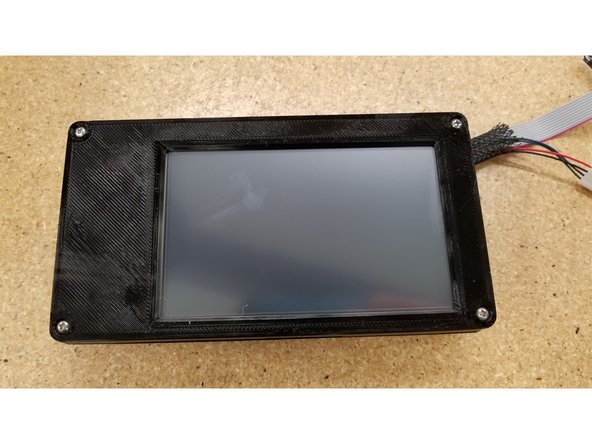
Peel the film off the touch screen.
-
Make sure to enjoy the satisfying feeling of peeling the film off new electronics. Yeah...that's nice.
-
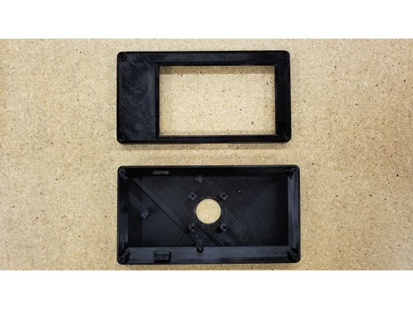
Locate the front and back half of the screen enclosure for the following steps.
-
-
-
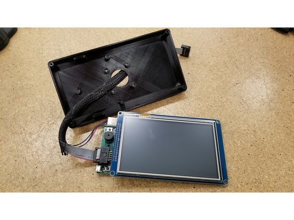
Pass the cables through the hole in the back of the enclosure, and insert the screen as shown.
-
Be sure that the back enclosure half is oriented as seen in the photo, using the board standoff posts as a reference point.
-
-
-
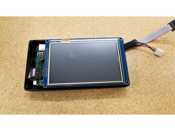
Align the front half of the screen enclosure as seen.
-
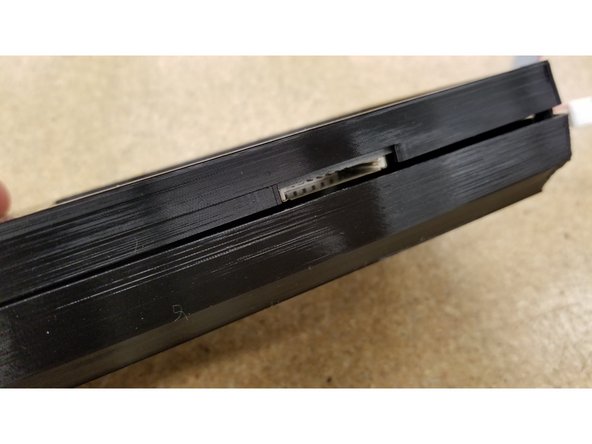
Make sure the opening for the SD card lines up with the SD card slot at the bottom of the screen.
-
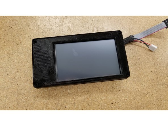
Secure the two enclosure halves together using the four #4 1/2" L sheet metal screws
-
-
-
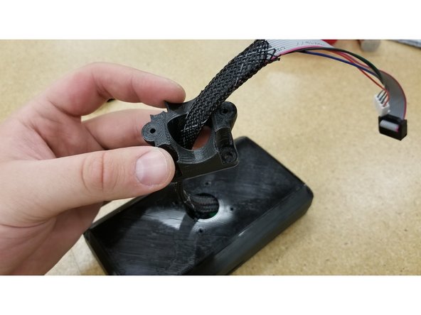
Locate the screen mounting saddle and pass the cables through as shown.
-
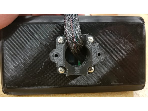
Position the saddle on the enclosure as shown, ensuring the two screw mounting points are parallel to the screen.
-
Secure the saddle in place using four #6 1/2" L sheet metal screws.
-
-
-
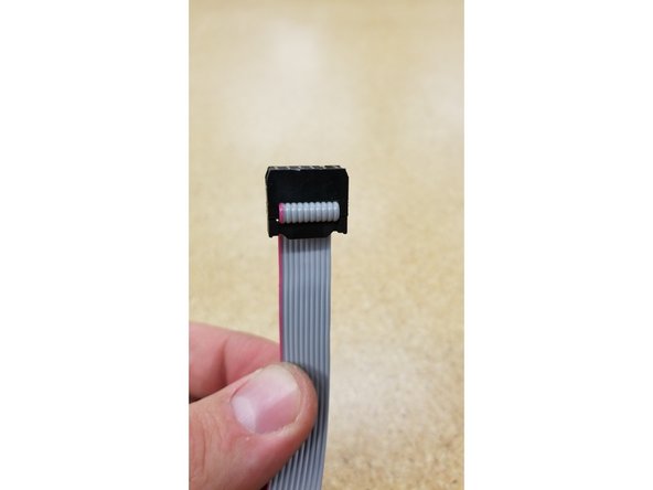
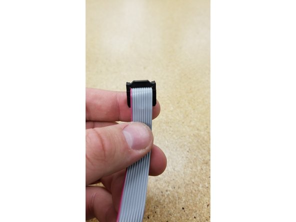
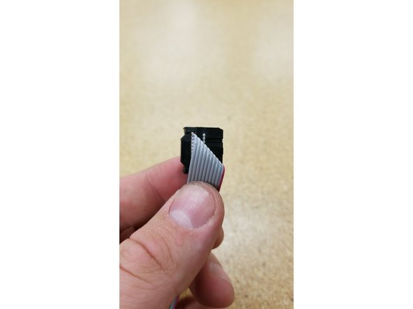
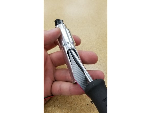
Hold the loose end of the ribbon cable and fold it exactly as shown in photos 1, 2, and 3.
-
-
-
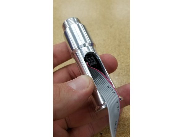
CAREFULLY wedge the ribbon cable through the screen mounting post as shown. The black connector will only fit through the tube sideways!
-
You may need to use a thin screwdriver or pen to help guide the cable connector through the post.
-
CAUTION: This is a tight fit, so it will require some force to install by design, but be very careful not to pinch the ribbon cables to the point of breaking or stripping on the edges of the post.
-
-
-
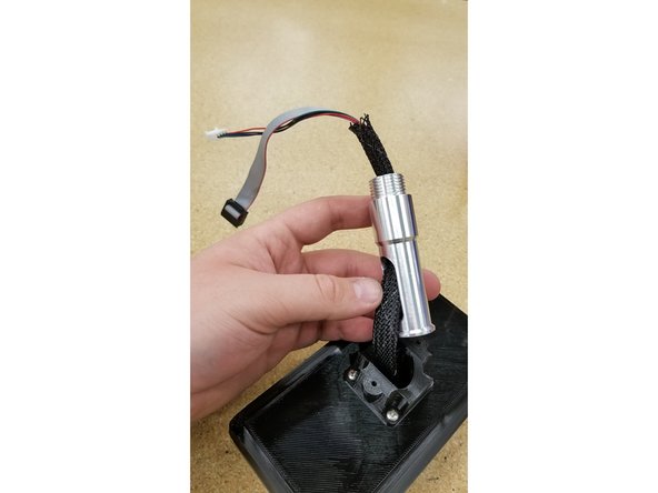
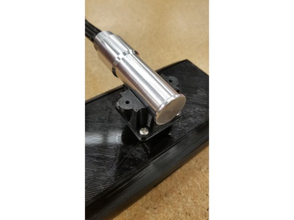
Pull out the slack in the cables between the saddle and the mounting post, and place the mounting post in the saddle.
-
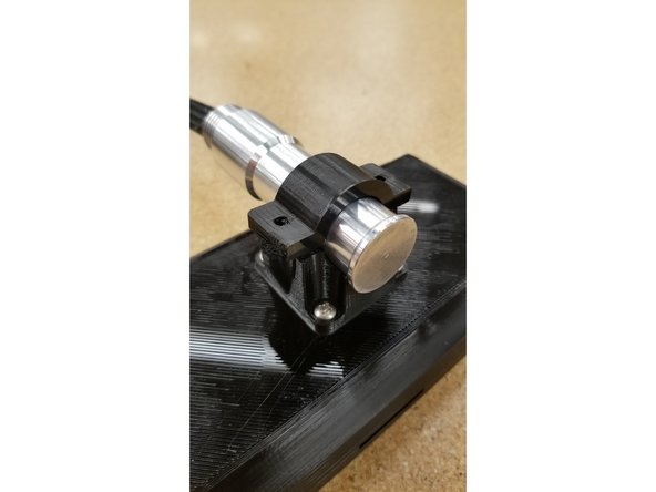
Use the mounting post clamp and two #6 1/2" L sheet metal screws to cage the mounting post in position.
-
Tighten the screws for rotational friction on the poat at your own personal discretion.
-
-
-
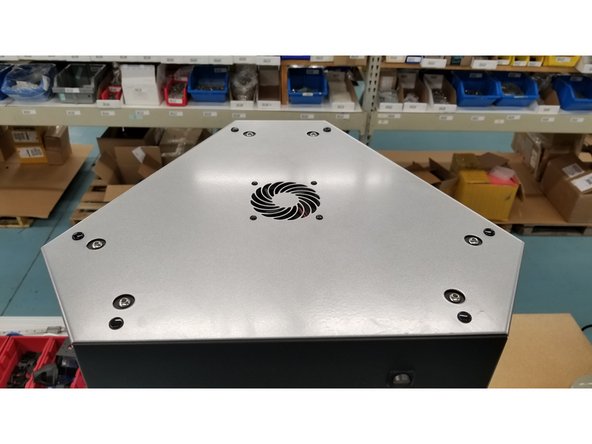
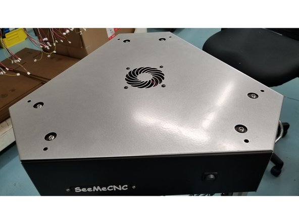
Remove the top cover from your printer.
-
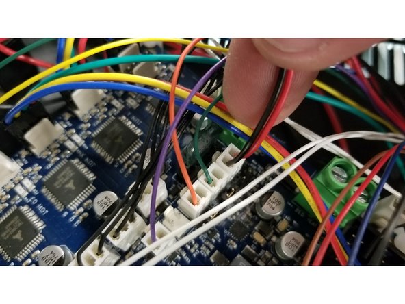
Be sure to take note of the location and unplug the two pin fan connector from the Duet.
-
-
-
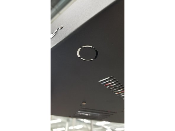
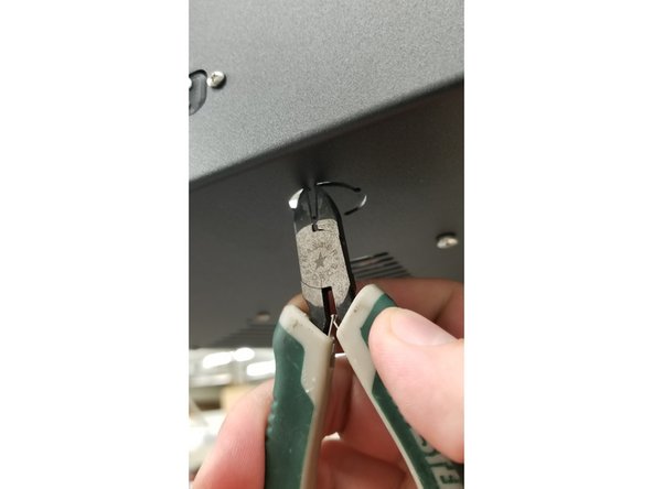
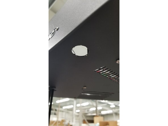
Snip the for tabs on the mounting post hole at the bottom of the top machine assembly using sharp, strong snippers.
-
Be VERY careful, as the sheet metal can be very sharp on the areas where the tabs were after you've snipped them off. It's recommended to carefully file down the tabs to smooth them out and avoid getting cut.
-
-
-
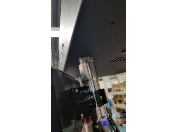
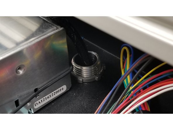
Pass the cables through the screen arm assembly and post mounting hole as shown.
-
Install the mounting post locking nut and tighten to your heart's content.
-
-
-
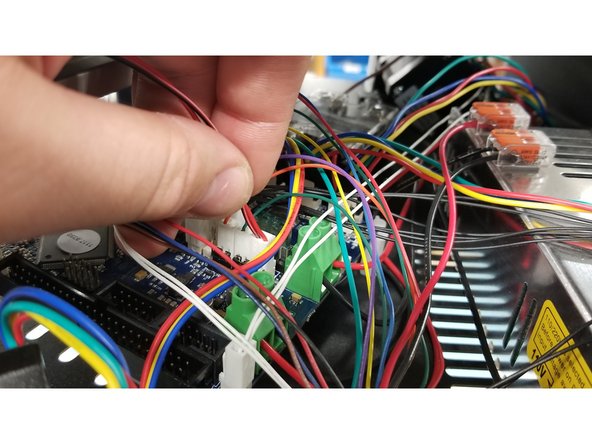
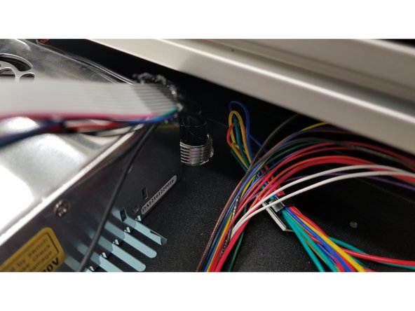
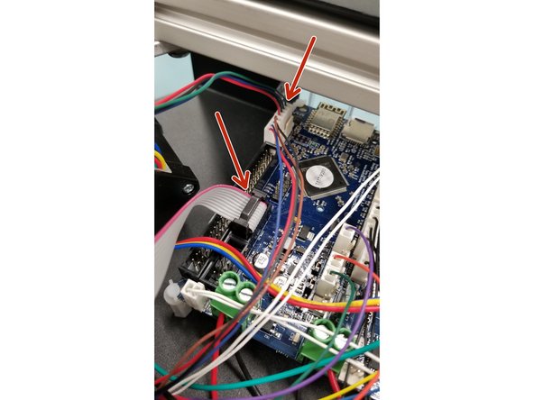
Plug the cables into the Duet board as shown, and replace the top cover on your printer.
-
Be sure to re-install the two pin fan connector you removed earlier!
-
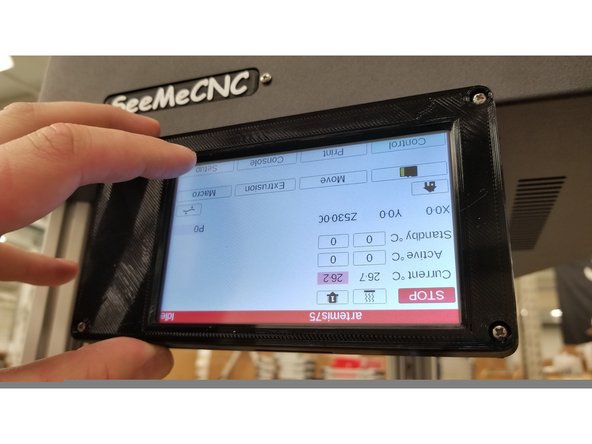
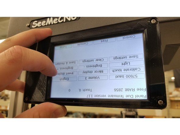
Turn the machine on, and touch the dots to calibrate the screen.
-
The screen should be inverted from the factory. We will change this setting in the next step.
-
-
-
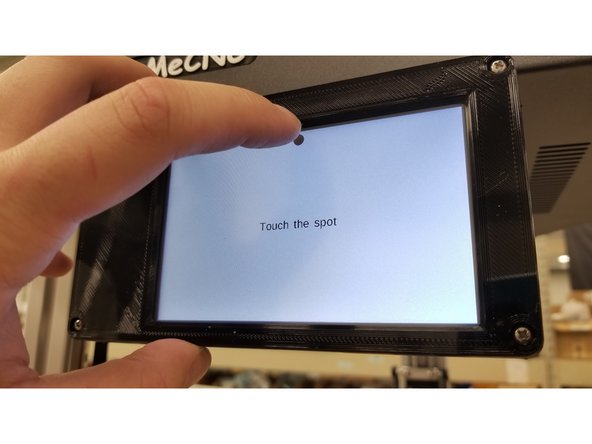
Select "Setup" > "Invert Display"
-
Re-calibrate the screen by touching the dots.
-
-
-
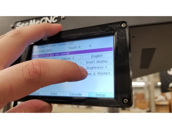
Newer firmware (July 2018 forward) will no have "Save & Restart". Simply push "Control" button to switch screens and the inverted display will be saved.
-
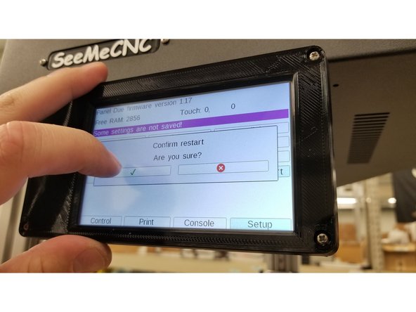
Select "Save & Restart" > green check mark .
-
-
-
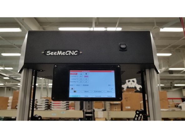
Enjoy your new touch screen!
-
Be sure not to rotate the screen too far in either direction, as it could pinch and possibly damage the cables.
-


Cancel: I did not complete this guide.
2 other people completed this guide.
2 Comments
Open and inspect the contents of your touch screen kit to ensure you have all the parts Photoshop error 16 listed on the BOM. This is a really good post. Must admit that you are amongst the best bloggers I have read. Thanks for posting this informative article.
Albert John - Resolved on Release Reply