
-
-
The timing pulleys feature two grub-screws for locking the gear on to the stepper motor shaft. Ensure that one of the two screws is aligned with the flat section of the stepper motor shaft as shown.
-
When installing the grub screw, some users recommended that you use a thread locking compound (typically Locktite Blue or similar) on the threads. This is completely optional but could prevent the screws from loosening over time and causing print problems.
-
Align the top face of the pulley with the top face of the stepper motor shaft as shown in the second photo. It will be offset approximately .5mm from the end of the shaft. This is required for proper belt alignment once the stepper is installed in the next step.
-
-
-
The end-stop switches used in this step can be found inside the Rambo controller packaging.
-
YOUR END STOP SWITCHES COME WITH A SMALL ACTUATING LEVER, CAREFULLY REMOVE IT. IF YOU DON'T, YOU WON'T FIND OUT WHY UNTIL YOU DISCOVER THAT ALL THREE END-STOP SWITCHES ARE HELD CLOSED AGAINST THE TOP BASE PLATE. DON'T ASK HOW I KNOW.
-
-
-
You'll need a #1 Phillips screwdriver in order to install the 2-56 screws used to fix the end-stop switches in place. Take care to not over-tighten the screws! The switch body is delicate and is easy to crush.
-
Do not Fully Pre-Assemble the motor mounts. Use this animation as a reference only.
-
-
-
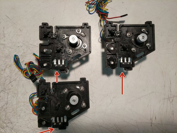
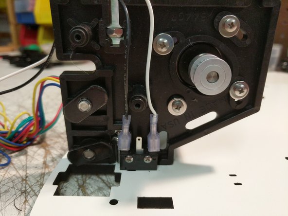
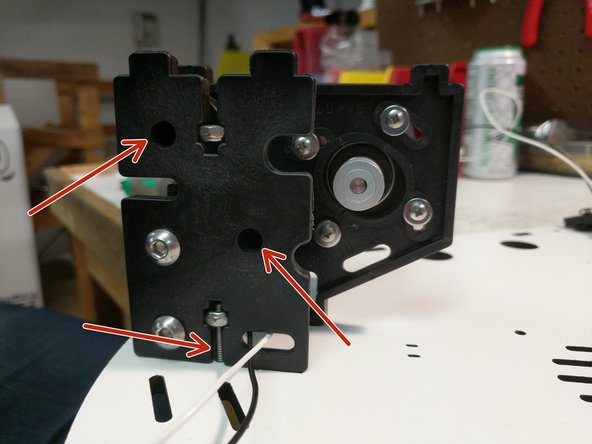
When installing the end stop switches, please make sure that they're oriented as shown in the photos. (The red arrow is indicating the "button" on the switch. It should be closest to the TSLOT hardware.
-
First install the end stop switches. You'll need a #1 Phillips screwdriver in order to install the 2-56 screws used to fix the end-stop switches in place. Take care to not over-tighten the screws! The switch body is delicate and is easy to crush. The holes are not tapped/thread.
-
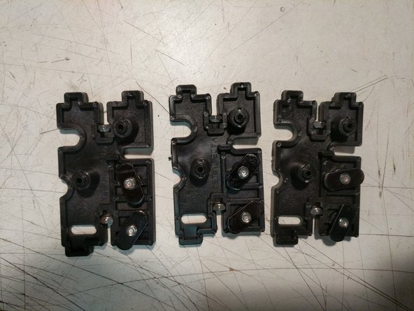
Insert the 6-32 nylon lock nuts into their pockets. (2 per injection molded piece).
-
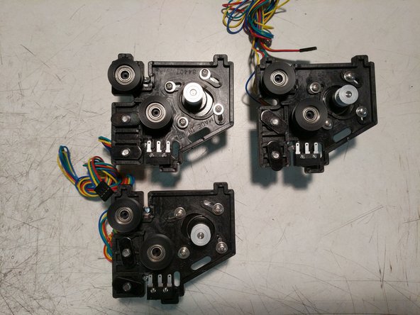
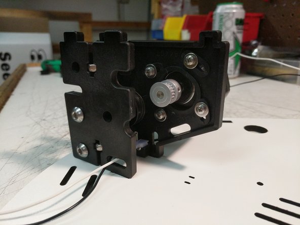
Next install the stepper motors using (4) M3 x 10mm screws and washers. Do not tighten these screws. The stepper motor pivots to allow for tensioning the belts (completed later)
-
Install the TSLOT hardware. Remember to only start the 1/4-20 button head screws into the TSLOT nuts.
-
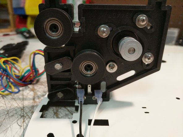
Install two bearing / cover assemblies per injection molded plate. (this is different than the base assembly which only used 1 bearing / cover assembly per plate)
-
If you've reached this point and the little metal lever arms are still on your end stop switches, REMOVE THEM RIGHT NOW. Carefully mind you, but REMOVE THEM.
I believe that having the motor wires exit in the direction of the limit switches will result in the cleanest wiring. (I had mine in the opposite direction and changed it when I got to step 10.)
Steve Hansel - Resolved on Release Reply
-
-
-
Insert the 6-32 nylon lock nuts into their pockets. (2 per injection molded piece).
-
Install the TSLOT hardware. Remember to only start the 1/4-20 button head screws into the TSLOT nuts.
-
-
-
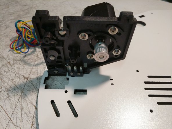
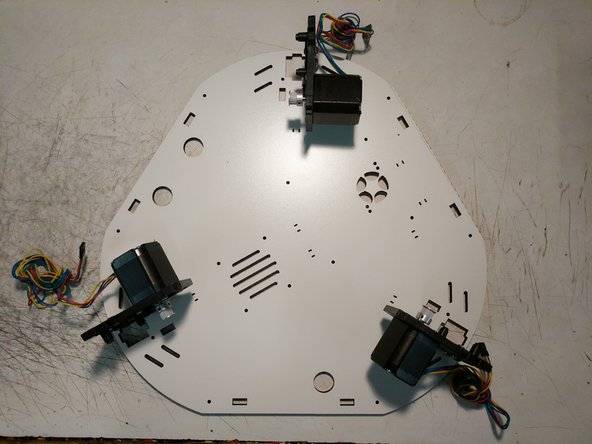
Install the (3) motor mounts on the Top Base Plate using (1) 6-32 x 1" screw per motor mount. Do not fully tighten these screws. Note the orientation of the Top Base Plate. There is laser engraved text on this plate noting which side should be DOWN)
As an asside to my previous tghe bottom base is assembled with the xyz laser printed facing up! Im now totally confu!
Stef
is.chowa@gmail.com - Resolved on Release Reply
Nope! nothing indicating which direction is down. Only the xyz tower location are marked are these supposed to point down? and motors rtc mounted on other side?
Stef
is.chowa@gmail.com - Resolved on Release Reply
-
-
-
The end stop wires are located in the RAMBo box. They are the black and white wires pre terminated with a blade connector one end and a metal latching connector on the other end. There should be 6 total end stop wires.
-
Begin with the Z tower location and install a pair of end stop wires on the end stop as shown.
-
After installing the wires, bend the end stop over as shown.
-
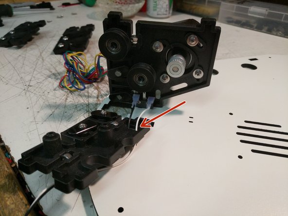
Route the two wires through the Idler Plate as shown.
-
Perform this operation for the X & Y tower assemblies.
Only found 6 black wires with contacts. can’t find the connection sockets that these go into, as no Rambo or box!
Stef
is.chowa@gmail.com - Resolved on Release Reply
-
-
-
You can now attach the idler motor plate to the motor mount plate using (2) #4 x 1/2" screws. The plate can be tilted into position. You will then need to align the bosses of the plate with the bearings and press the plates together.
-
Secure the assemblies to the laser cut Top Base Plate with the 6-32 x 1" screws. You CAN fully tighten these screws at this time.
-
Perform this operation for each of the three assemblies.
-
Route the wires around the top assembly as shown. All wire will pass the hole in the idler plate for containment. The image has arrows indicating the direction that the wiring is traveling.
No Rambo, no wires or connectors. Am I in the wrong build guide?
Stef
is.chowa@gmail.com - Resolved on Release Reply
-
-
-
There are (3) 3 pin connectors in the RAMBo kit required for this step.
-
Label one each of the connectors with X Y & Z
-
Determine and separate the pairs of wires and note their tower positions (XYZ). This is easy to do by length, since the wires are routed around the printer. X wires will the longest, Z the next longest, and Y the shortest.
-
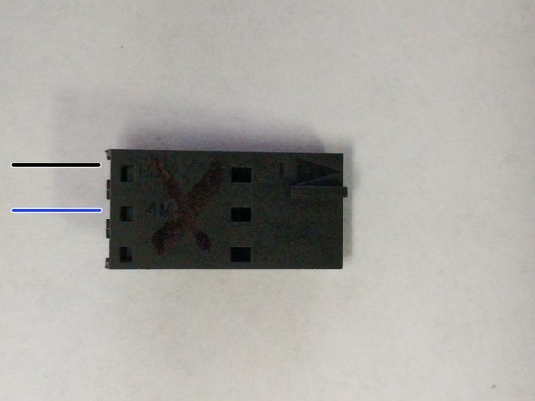
In the first image the wiring positions are noted with colored lines. Black will be for the black wire. Blue will be for the white wire. The plastic connector has an arrow molded into the part. This arrow is the indicator for pin 1.
-
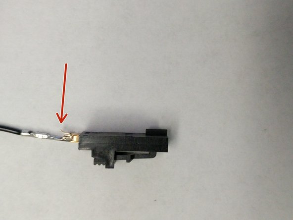
Insert the black end stop wire into 3 pin connector into pin 1 (reference the image for correct installation. The red arrow in the image is indicating the latching mechanism, that should be facing up).
-
Insert the white end stop wire into 3 pin connector into pin 2 (middle position. This will insert the same as the black wire).
-
Bundle the wires together and attach them to the Top Base Plate with a Zip Tie. as shown.
Important - you need to fully seat the pins in the connector. There are several stops where it feels like the pin is fully seated, but it isn't. IF you can see any part of the pin out of the back of the connector, the pin isn't pushed in far enough (wasted a fair amount of post-assembly troubleshooting on this). A close-in picture showing the connector with the pins properly seated would be helpful. Much more helpful than the current third image.
Also, make sure you are inserting the pins into the 3-pin connectors and not the 4-pin connectors. Did that, and it was a pain to fix.
-
-
-
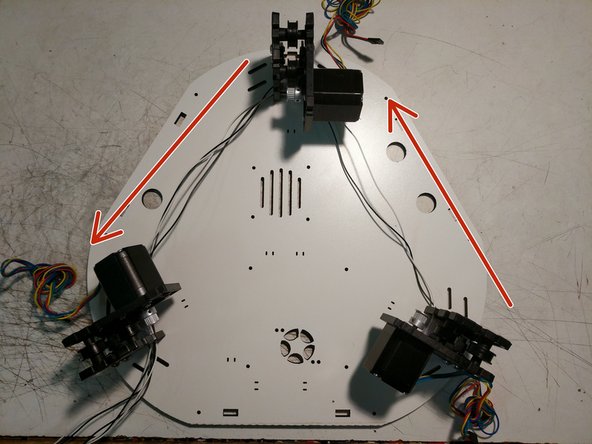
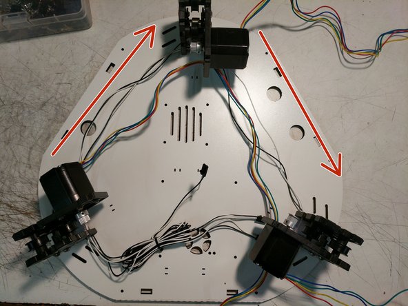
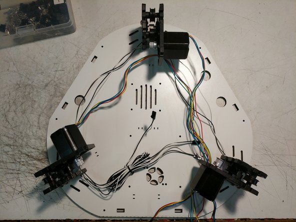
You will now route the stepper motor wires in the opposite direction that you routed the end stop wires. Note the arrows on the image for direction. The wires will route through the motor mount plate in the location indicated by a red arrow in the first image.
-
-
-
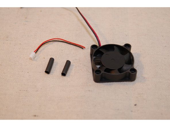
For this task, you'll need the 30mm length of heat shrink tubing, the connector you clipped from one of your 25mm cooling fans and the 40mm Rambo cooling fan, as shown.
-
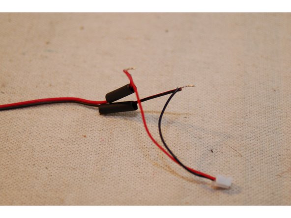
Cut the 30mm heat shrink in half and set it aside. Strip about 6mm from each of the fan and connector wires.
-
Slip the heat shrink on to the fan leads and then solder the connector to the fan leads.
-
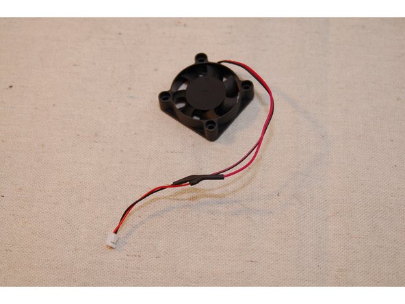
Cover the solder joint with the heat shrink tubing and shrink it!
-
-
-
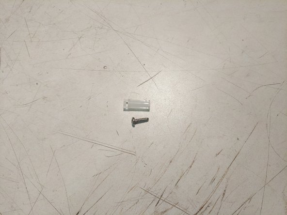
Locate the (4) Board Supports and (4) #6 x 1/2" screws indicated in the image. These are located in hardware pack #84489
-
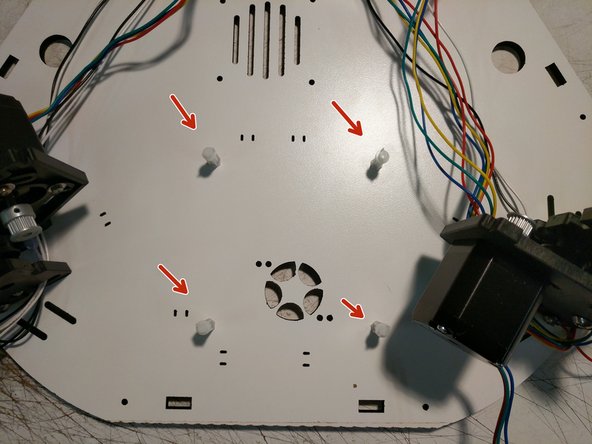
Attach the board supports to the top base plate in the locations shown.
-
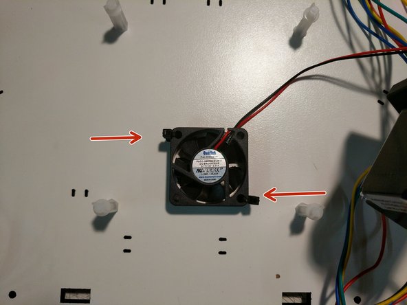
Attach the fan that you prepared in the previous step to the top base plate using (2) zip ties as shown. Note the correct orientation of the fan. The label will be facing up.
-
The fan has a directional arrow on the side, showing the flow of air. It should be installed so it will blow up at the RAMBo (when installed)
Leave the board supports slightly loose. Unless you know how these work, you will likely have at least one rotated in the wrong position. (Even the photo does.) Plus later when you install the board you will need to use less force.
Steve Hansel - Resolved on Release Reply
-
-
-
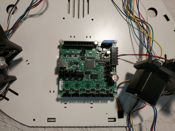
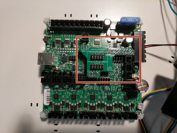
The RAMBo board should be installed in the machine. The board supports will capture the corners of the RAMBo board. You will need to flex the board supports to get them over the corners of the board.
-
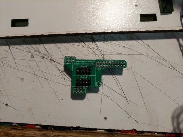
Locate and install the LCD adapter onto the RAMBo board in the position indicated. Ensure that you properly align the pins and headers of both components.
If you left the board stands slightly loose as I suggested in the last step, you can tighten them after the board is installed.
Steve Hansel - Resolved on Release Reply
-
-
-
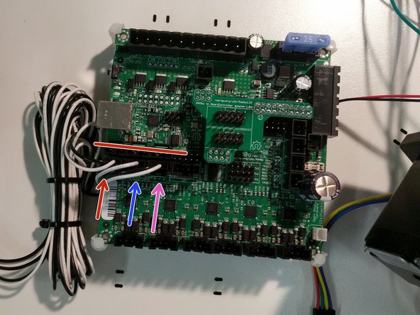
Plug the end stop wires in the correct locations on the RAMBo board in the MAX locations. Ensure that you get the correct X Y Z locations.
-
In the image, X = Red Y = Blue Z = Magenta. The red line is covering the MIN end stop location that are not used.
-
Secure the end stop wires with an additional zip tie if desired.
-
-
-
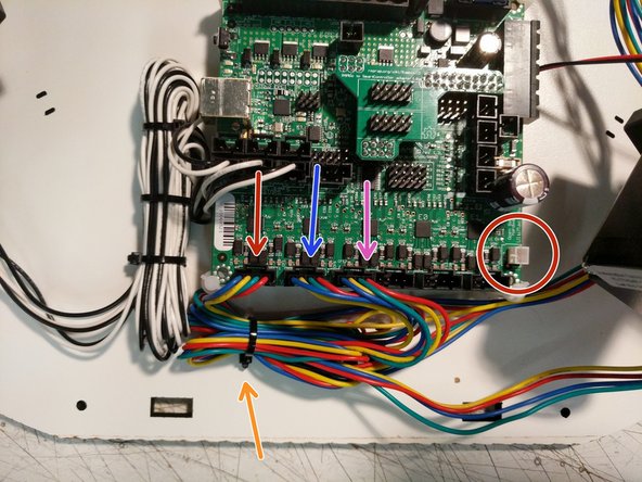
Plug the stepper motor wires in the correct locations on the RAMBo board. Ensure that you get the correct X Y Z locations.
-
In the image, X = Red Y = Blue Z = Magenta.
-
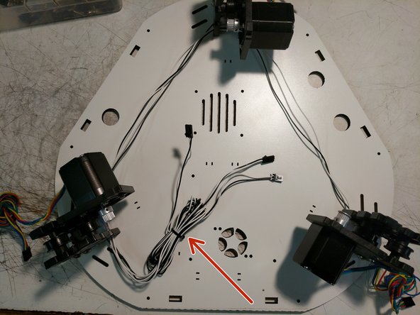
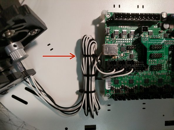
Secure the stepper motor wires to the top base plate with a zip tie in the location indicated.
-
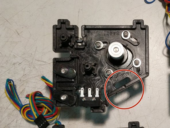
Finally, you can plug the RAMBo's 40mm cooling fan in at the connector marked by the red circle.
-
This completes the top assembly preparation. Next, we will focus on the final assembly of the build.
-
-
-
You have now completed the base and top assemblies. We will join the two together in the next section.
-
Proceed to: Step 4. REV2 Rostock Max v3 Final Assembly
-


Cancel: I did not complete this guide.
11 other people completed this guide.
