-
-
First, click here to read safety information . This safety information may be updated at anytime so occasionally check for updates.
-
NOTE: This guide is intended to be followed online in order to fully utilize the links and documentation found within.
-
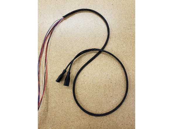
Open and inspect the contents of your SE300 whip kit to ensure you have all the parts listed on the BOM.
-
Included is a diagram of the whip wiring. Keep this handy, as we'll be referencing this throughout this guide.
-
-
-
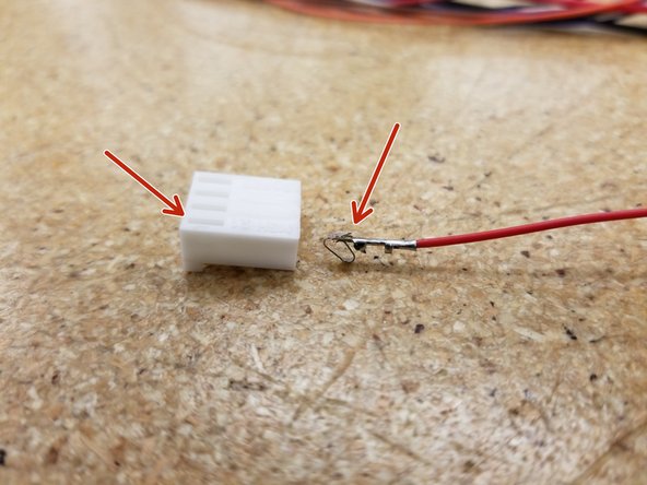
Begin inserting the wires into the black SL 10 position housing.
-
Be sure the small tab on the metal crimp terminal is facing the same direction as the square holes in the connector. If inserted properly, you should hear and feel a satisfying click as the tab seats. Give the wire a gently tug to make sure it's seated properly.
-
Repeat for the remainder of the wires, using the diagram from earlier as a guide.
-
-
-
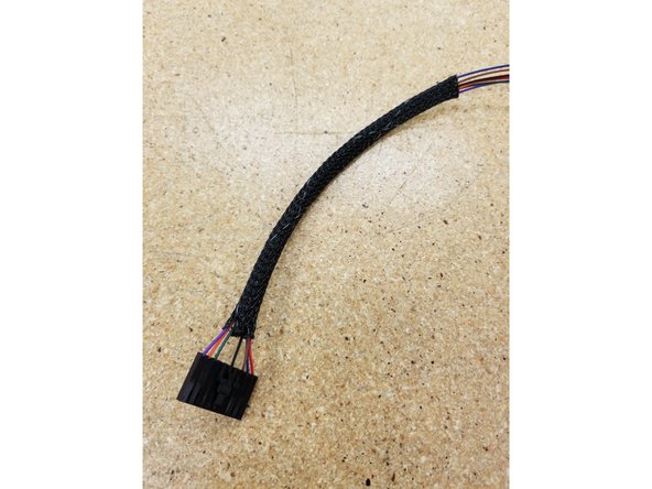
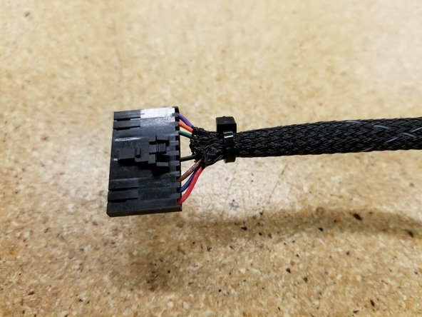
Pass the wires through one of the shorter lengths of mesh loom material.
-
Tightly zip tie the bundle to hold everything in place.
-
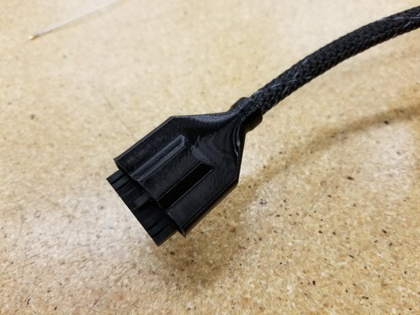
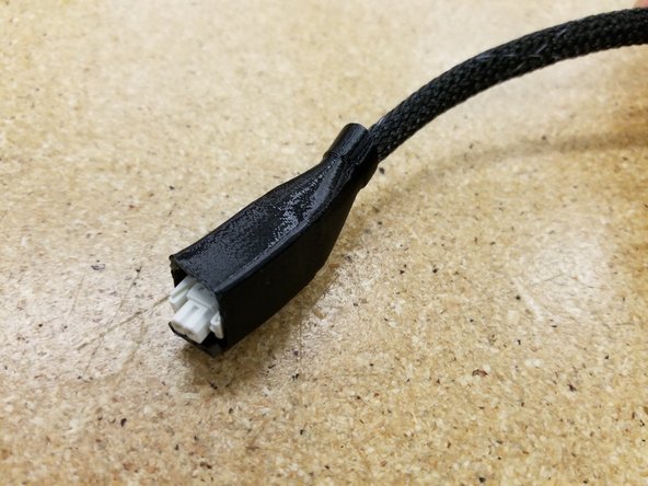
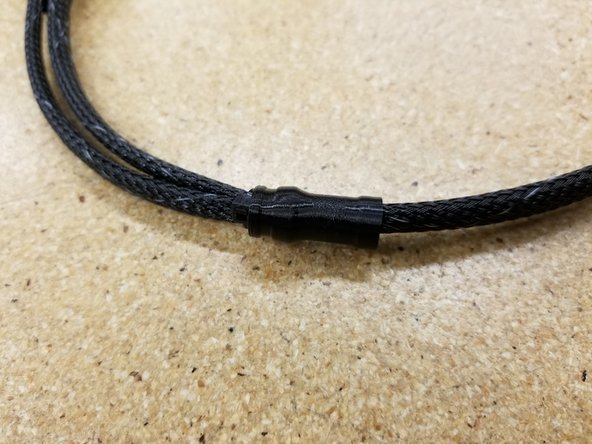
Run everything through the wider cable boot, covering the zip tie and connector.
-
-
-
Insert the two white wires in the 4 pin SL connector just as you did for the 10 pin SL connector in Step 2.
-
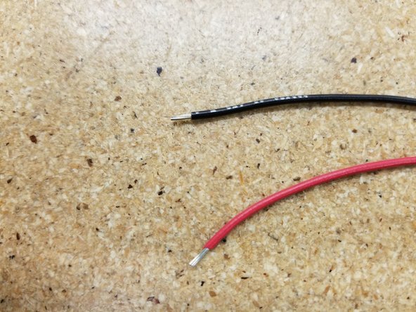
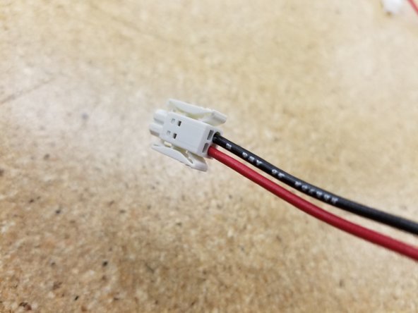
Make sure an adequate amount of the PVC has been stripped from the red and black 20awg wire, and insert into the 2 pin push-in wire terminal as shown.
-
Remember to use the wire diagram from earlier as reference when needed
-
-
-
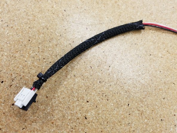
Pass the cables through the mesh loom, zip-tie them secure, and install the cable boot as we did in Step 3.
-
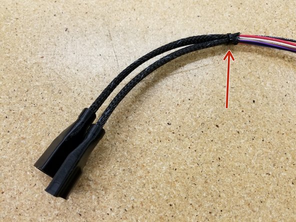
Zip tie the two cable bundles together at the top of the mesh looms as shown.
-
-
-
Pass all the cables through the mesh loom.
-
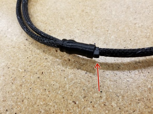
Rout the cables and mesh loom through the loom splitter, using it to cover the joint between the three sections of mesh loom.
-
Add a zip tie to the mesh loom, just above the loom splitter, to secure it in place. See photo for reference.
-
-
-
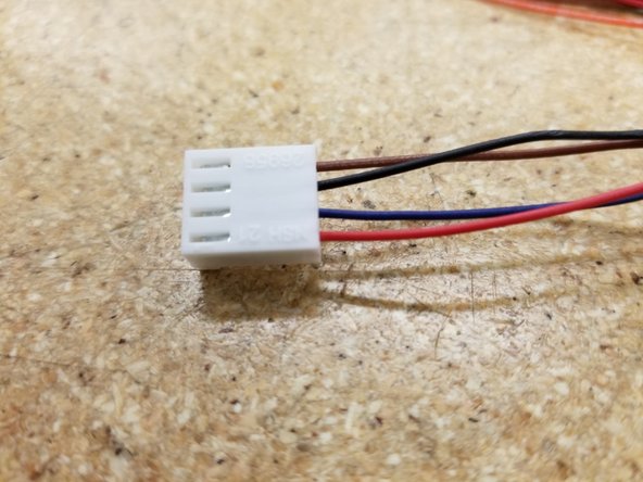
Insert the KK connectors as shown, making sure that the small tab on the metal wire crimp is aligned with the tab hole on the plastic connector.
-
Again, if inserted properly, you should hear and feel a satisfying click as the tab seats. Give the wire a gently tug to make sure it's seated properly.
-
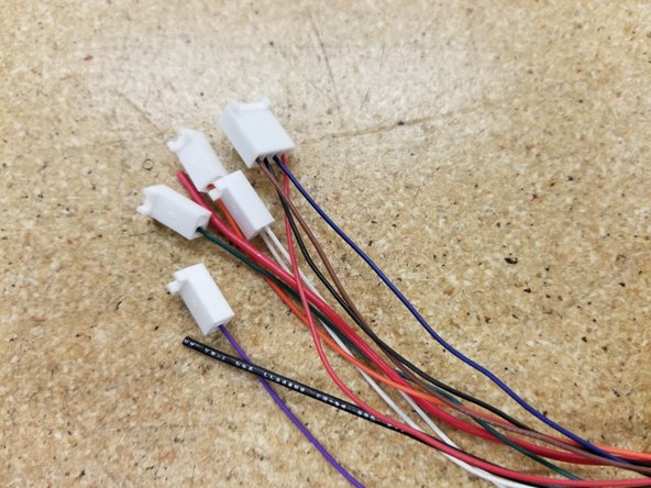
Repeat for the remaining KK connectors, carefully following the wiring diagram from earlier.
-
-
-
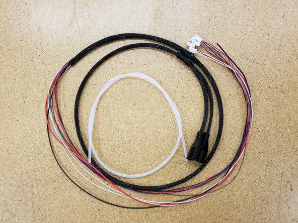
Use your completed whip in your machine!
-
The PTFE tubing is shown not installed as your installation may vary depending on which machine the whip is installed.
-