
-
-
Look over the included bill of materials (BOM) to make sure you have all required components for this install. A full sized BOM can be found attached at the end of this guide.
-
Not Pictured: 58708 PTFE 2mm ID x 4mm OD and 70630 2 into 1 Dual Filament Feed Y Adapter - Assembled
-
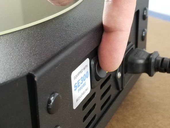
Turn off your RostockMAX v4 before following this installation guide!
-
-
-
Snip the zip tie off your EZR Struder plastics
-
-
-
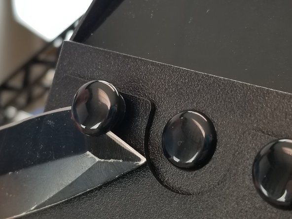
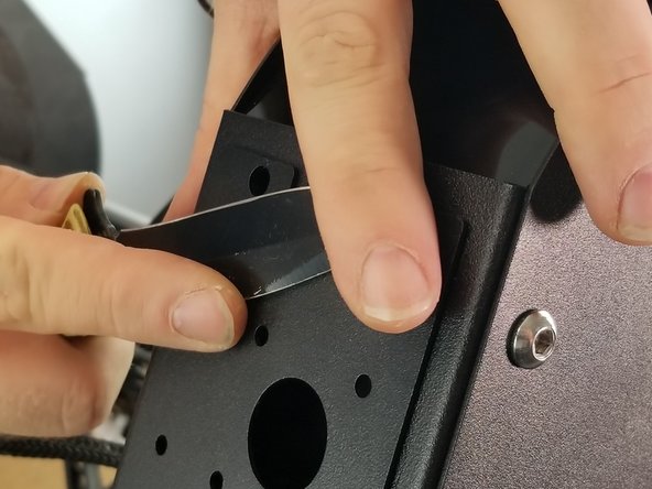
CAREFULLY use a thin object like a screwdriver or pocket knife to pop out all four plastic push rivets that are holding the extruder plate in place.
-
-
-
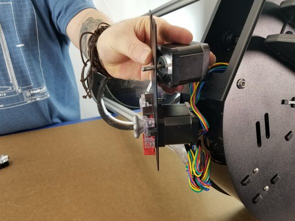
Grab your 26506 NEMA 17 Stepper Motor and place it on the back of the plate with the wires facing the center, just as the existing motor is installed.
-
Line up the motor screw holes with the holes on the extruder plate.
-
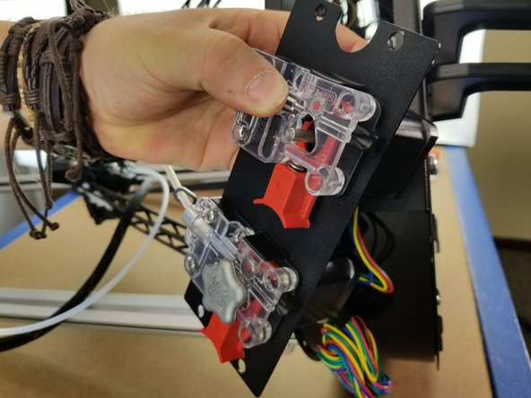
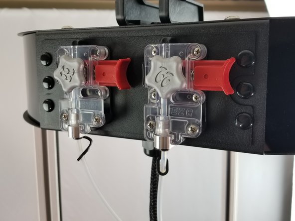
Place the EZR Struder plastics over the plate in the same orientation as the existing extruder.
-
-
-
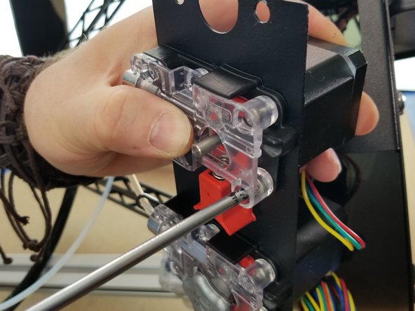
Use the included 30449 M3 - 0.5x 10mm L Phillip Pan Head Machine Screws to attach the EZR Struder and stepper motor to the extruder plate
-
-
-
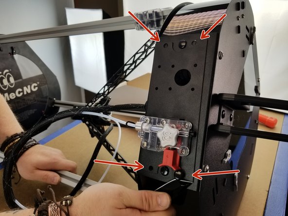
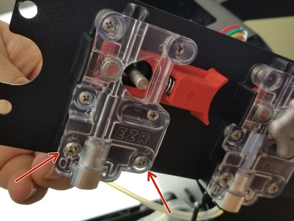
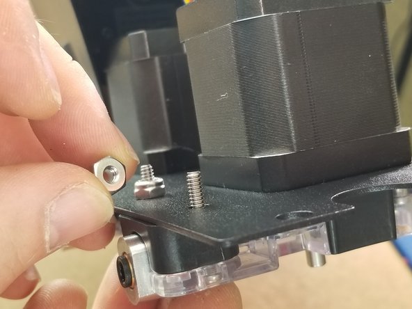
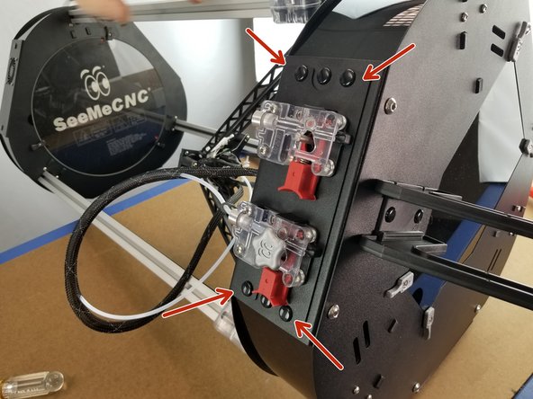
Use the included 30115 6-32 x 7/8"L Phillip Pan Head Screws and 30164 6-32 Nylon Lock Nuts in the locations shown to fasten the extruder in place, just as the existing extruder is.
-
-
-
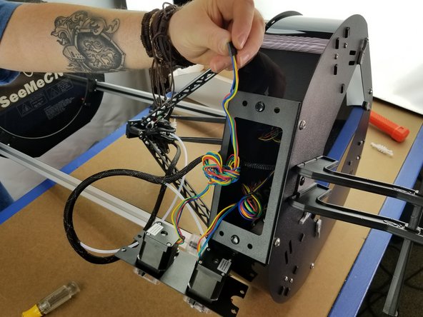
Pull some length out of the bundle of wires coming from the extruder motor.
-
Pass the motor plug and wires through the opening in the extruder panel on your machine
-
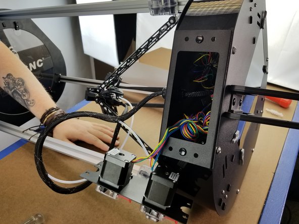
Place the extruder panel back where it belongs on your machine.
-
-
-
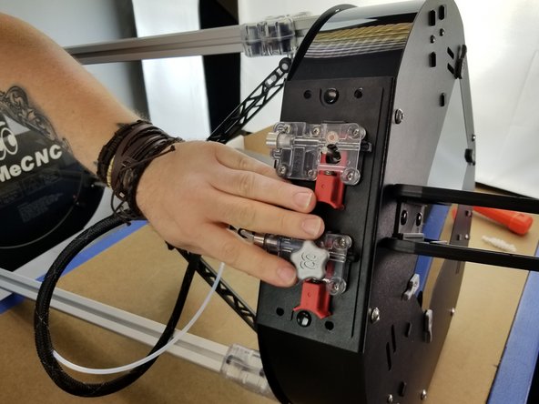
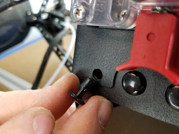
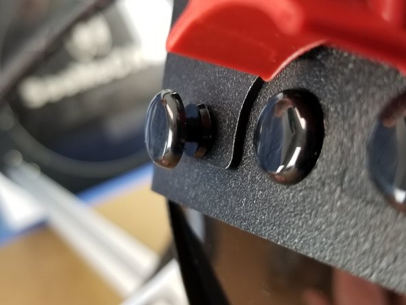
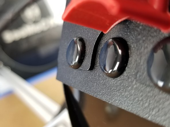
Re-install the plastic rivets by placing them in the mounting holes in the sheet metal, pushing the bottom portion in fully, then pushing the head until the rivet snaps in place flush with the sheet metal.
-
-
-
Repeat for all four holes indicated in the photo.
-
-
-
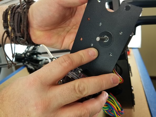
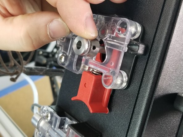
Grab your 70782 Direct Drive Roller (Hobbed Gear) and slide it on to the motor shaft.
-
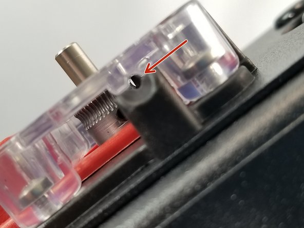
Do not line the set screw up with the flat of the motor shaft. The motor shaft flat is short, and the set screw will sit right on the corner of the flat, causing it to pop loose when tightened. Line the set screw up with a curved part of the shaft!
-
Make sure the curve of the hobbed gear teeth is lined up perfectly with the filament passthrough and the small bearing in the EZR assembly, as pointed out in the photo.
-
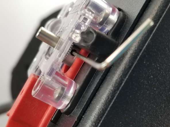
Tighten the set screw using the included 30039 1.5mm Allen Key
-
-
-
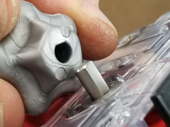
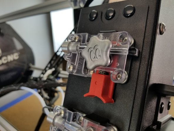
Install your 70714 Stepper Motor 5mm Shaft Handwheel, lining the flat of the hole up with the flat of the motor shaft.
-
-
-
Open the top acrylic hatch of your printer
-
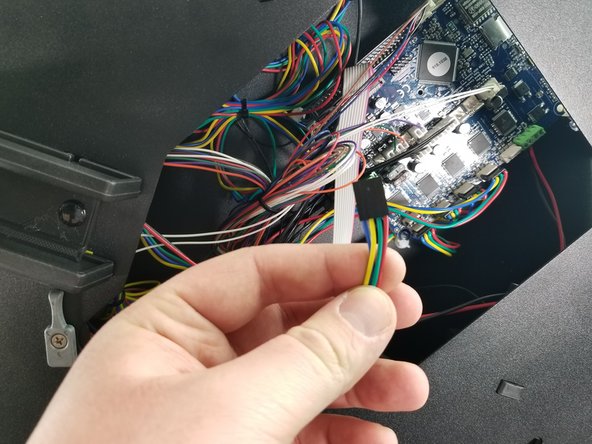
Find the plug from the extruder motor you just installed
-
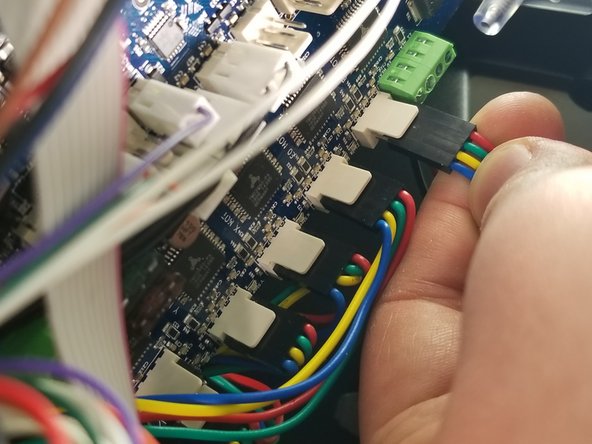
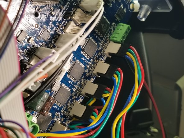
Plug it in to the Duet in the position shown in the photos, with the smooth side of the black plug facing inward towards the Duet board, as shown
-
Re-install your acrylic top hatch cover
-
-
-
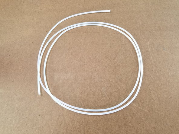
Cut a length of the included 58708 PTFE 2mm ID x 4mm OD tubing that's approximately 32"
-
There is enough tubing included to cut yourself two full tubes, giving you the option to replace your current tube if you want, or save it for future replacements if needed.
-
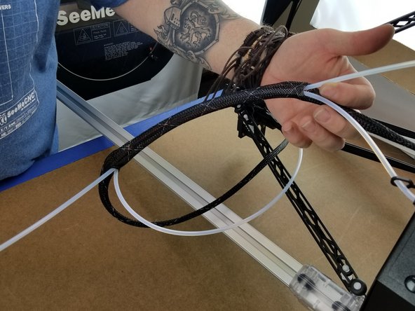
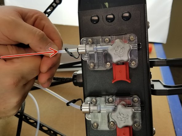
Pass the PTFE tube through the whip's mesh loom as shown, following the same path and holes as the existing PTFE tube.
-
-
-
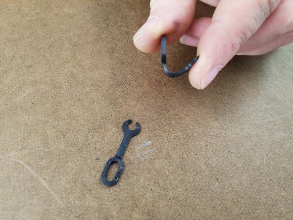
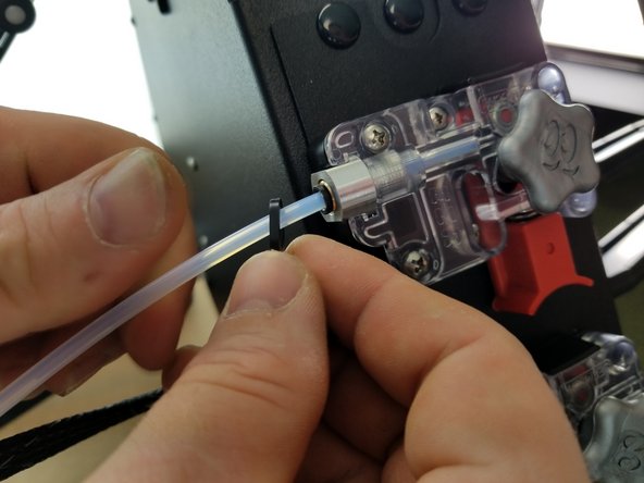
Grab your 33010 Lanyard PTC for 4mm Guest Fitting Cartridge
-
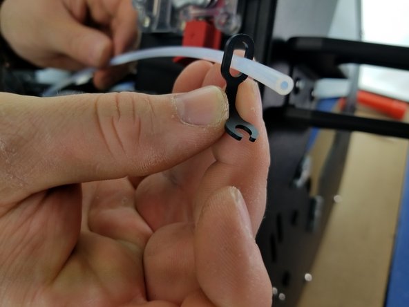
Pass the PTFE through the closed oval end of the lanyard
-
Insert the PTFE tube into the PTC fitting on the EZR Struder. Make sure it's pushed all the way through until it stops.
-
-
-
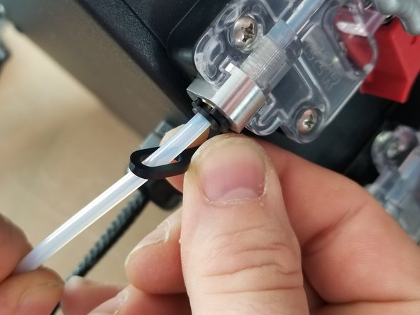
Clip the "C" shaped end of the lanyard into the black ring of the PTC fitting
-
Press the PTFE tube into the EZR after locking the PTC fitting with the lanyard to ensure it is fully seated and locked in place.
-
-
-
The following steps will be easier if you lower the hotend to the glass bed
-
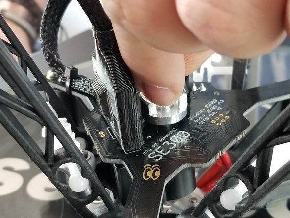
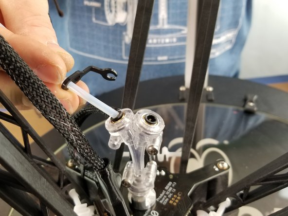
Un-clip the lanyard from the PTC fitting on the Hotend
-
Press down on the black ring of the PTC fitting and pull the PTFE out
-
-
-
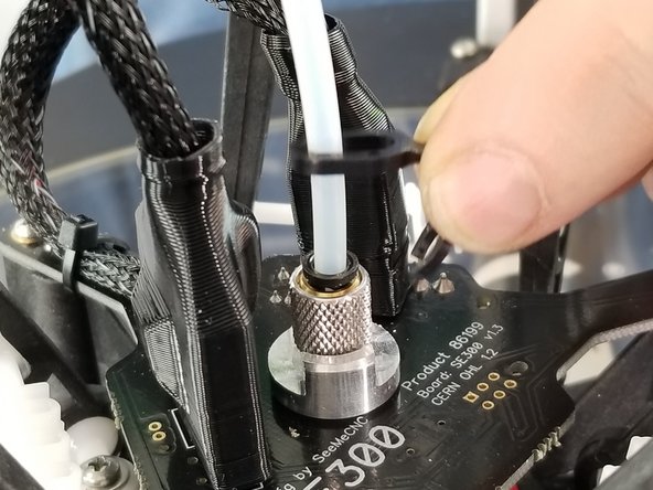
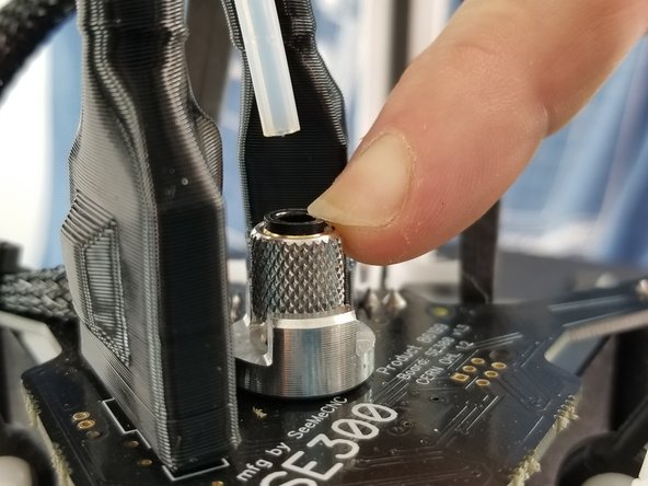
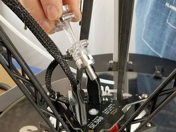
Carefully loosen the locking nut from the knurled PTC assembly
-
Unscrew the knurled PTC assembly from the top of the hotend
-
The PTFE liner inside the hotend chamber might come out with the PTC assembly. If this happens, just insert it back in place
-
This dual extrusion kit comes with an extra PTFE liner for your hotend. You don't have to replace it, but this gives you the option of replacing it during this install if you so choose.
-
-
-
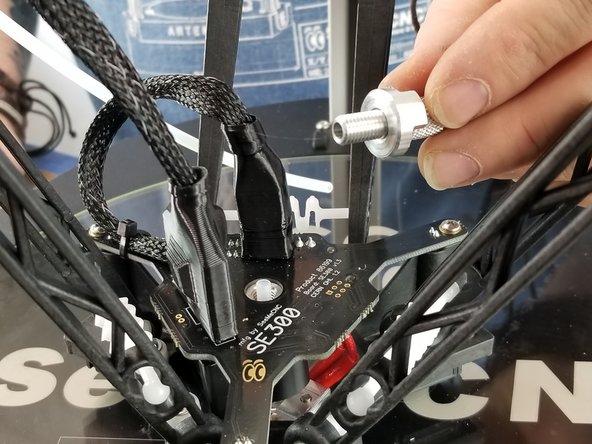
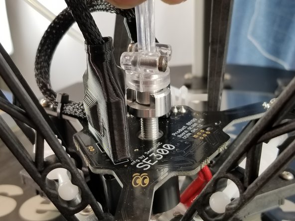
Screw in the Y Adapter assembly
-
IMPORTANT: Screw in the Y Adapter until you feel resistance from the PTFE liner, then turn another half turn or so. NO MORE THAN THAT. You could crush your PTFE liner tube and cause filament jams if it's tightened down too far.
-
-
-
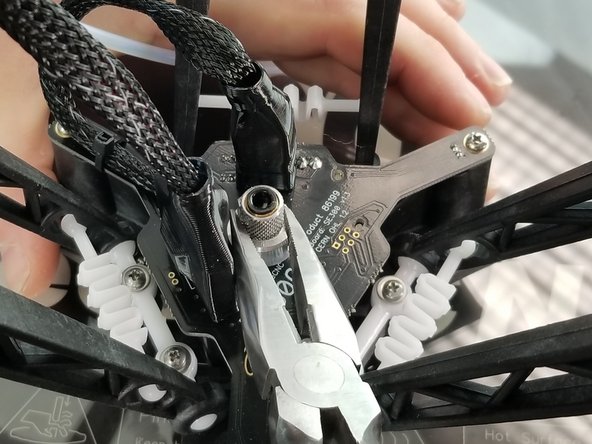
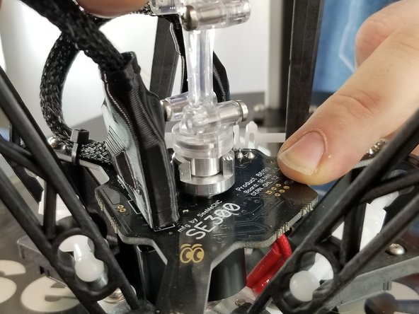
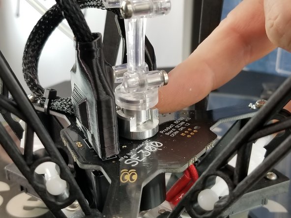
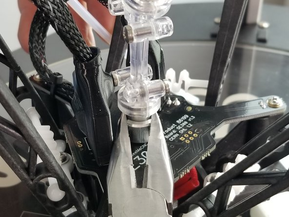
Finger tighten the locking nut, then carefully tighten fully with a pair of pliers.
-
Make sure the heat sink on the hotend is fully seated into the hotend circuit board when doing the final tightening.
-
-
-
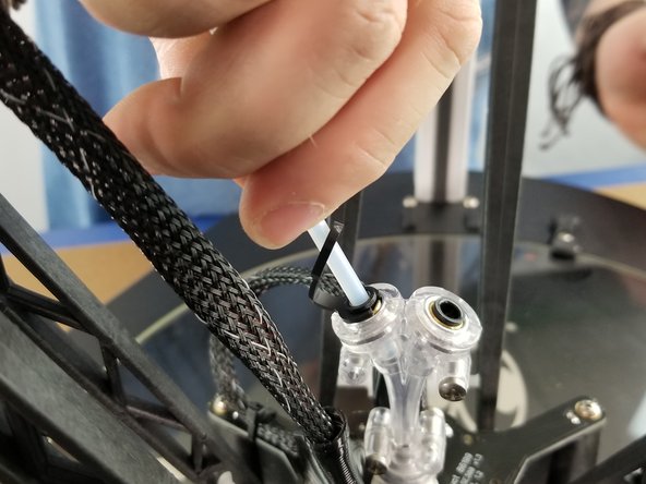
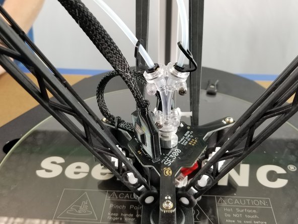
Install the PTFE tubes into the Y Adapter and clip the lanyards in place, just as you did on the EZR Struder
-
Remember to press the PTFE tube in further once the lanyard locks the PTC fitting in to fully seat the tube.
-
If you are following this guide as a side track from your RostockMAX v4 DIY KIT assembly, go back to that guide at this point and return here when you're done with your build and configuration.
-
-
-
Turn your RostockMAX v4 back on
-
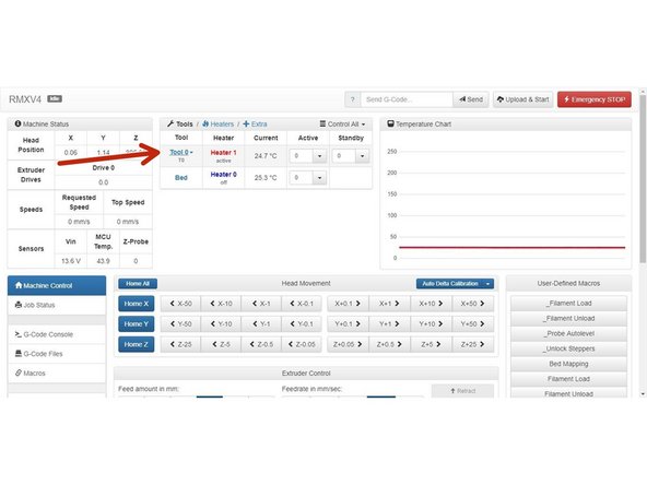
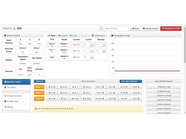
Connect to your printer through your web interface. You'll notice there is only one extruder listed. We're going to fix that now.
-
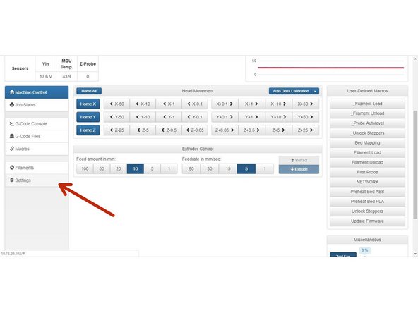
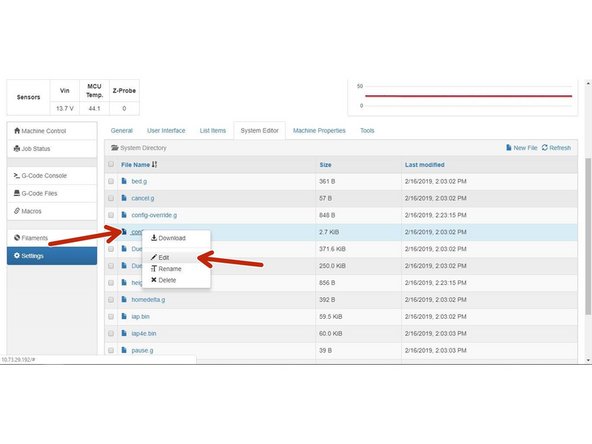
Go to the "Settings" menu
-
-
-
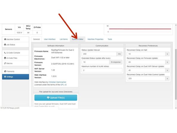
Go to the "System Editor" tab
-
Right click on the "config.g" file, and click "Edit" to open the config file
-
-
-
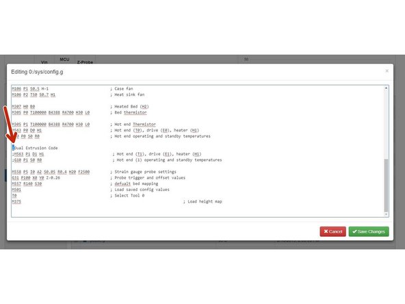
You'll need to scroll down to the "Dual Extrusion Code" section of the config file and "un-comment" out the dual extrusion portion of the file.
-
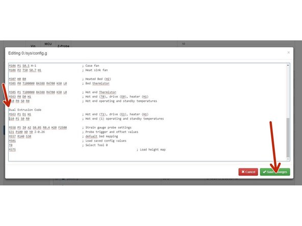
To do this, simply delete the semicolon ( ; ) at the beginning of all three lines, to match the second photo.
-
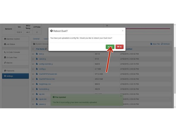
Click "Save Changes", and when the interface recommends a reboot click "Yes"
-
-
-
Your Duet should reboot and reconnect automatically. After it does this, you should notice two tools listed on the interface now. This means you did everything right!
-
Enjoy Dual Extrusion on your SeeMeCNC RostockMAX v4!
-
You may need to re-calibrate after this installation. If so, follow this guide to do so.
-
Check out this guide for preparing for Dual Extrusion in Cura
-


Attached Documents
