-
-
Proceed at your own risk.
-
First, click here to read safety information . This safety information may be updated at any time so occasionally check for updates.
-
NOTE: This guide is intended to be followed online in order to fully utilize the links and documentation found within.
-
Locate the components for your AC heated bed upgrade kit.
-
If you are missing parts or have a defective component, please submit a support ticket through the link under the 'Support' tab on the SeeMeCNC website.
-
-
-
Make sure the printer is turned off and unplugged before following this guide!
-
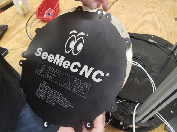
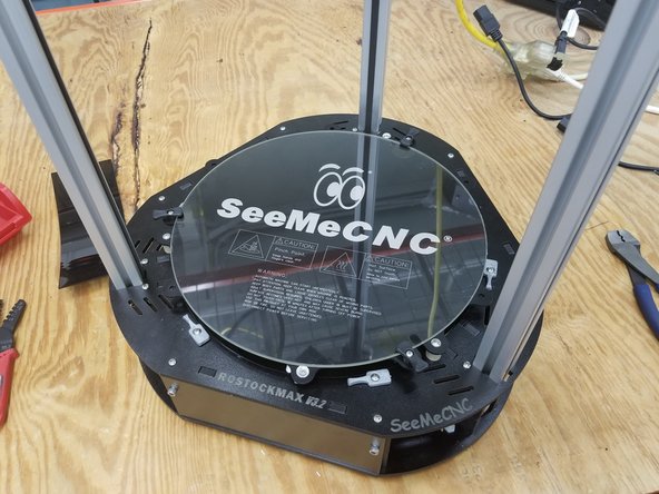
Remove and save boro glass plate for later
-
Cut existing power and thermistor wires near each soldering connection of the old Onyx heated bed.
-
-
-
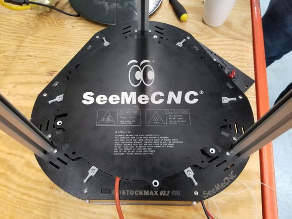
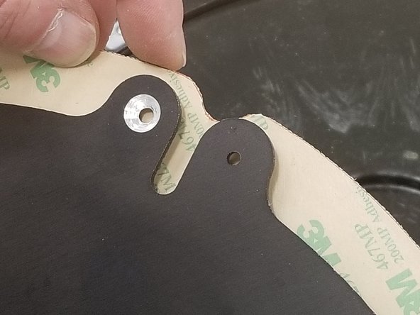
Place the new 84671 RMAXv4 Heat Spreader Laser Etched as shown to position holes.
-
Make sure the heat spreader is lined up with the hole where the bed glass previously sat as perfectly as possible before continuing!
-
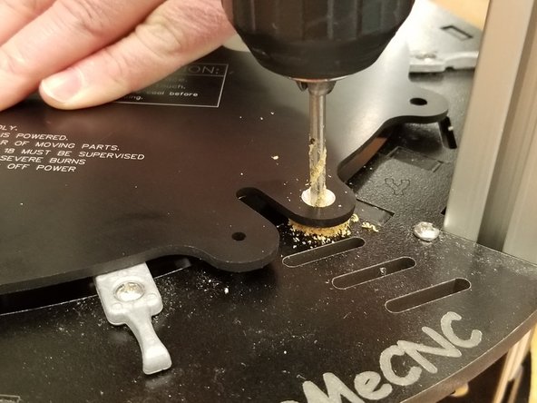
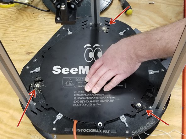
Use the 4mm (5/32") drill to make holes in the three places shown for later bed mounting
-
-
-
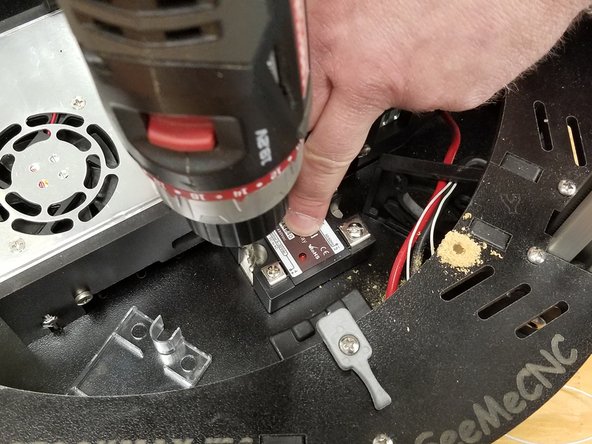
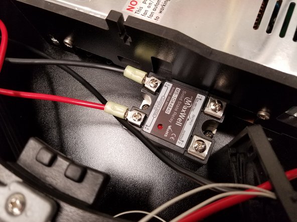
Remove the clear plastic cover from the 26193 SSR
-
Place the SSR in the machine as shown
-
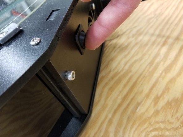
Mark and drill the mounting holes using the 4mm (5/32") drill
-
Position the AC output side of the SSR near the Y tower
-
Use the two 30117 6-32 x 5/8"L Phillip Pan head - SS and two 30164 6-32 Nylon Lock Nut - SS to secure the SSR in place
-
During this step would be a good time to vacuum or blow out the sawdust from your machine.
-
-
-
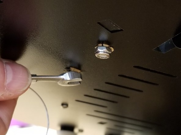
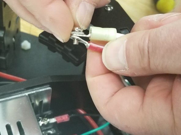
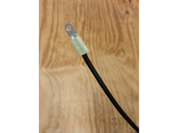
Strip 1/4" off the end of each of the existing black and red 12awg bed wires that were previously snipped.
-
Crimp the 26178 Ring Terminal Yellow Insulated for #8 Stud and 12awg as shown to the ends of the wires.
-
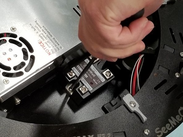
Attach the red wire to the V+ terminal number 4, and black DC- to terminal number 3 on the SSR
-
-
-
Be certain your machine is not plugged in to power before continuing!
-
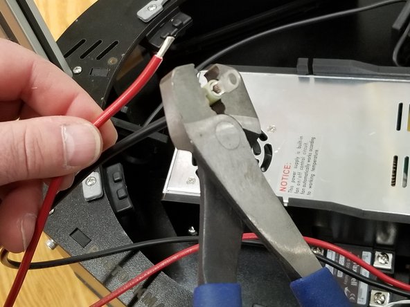
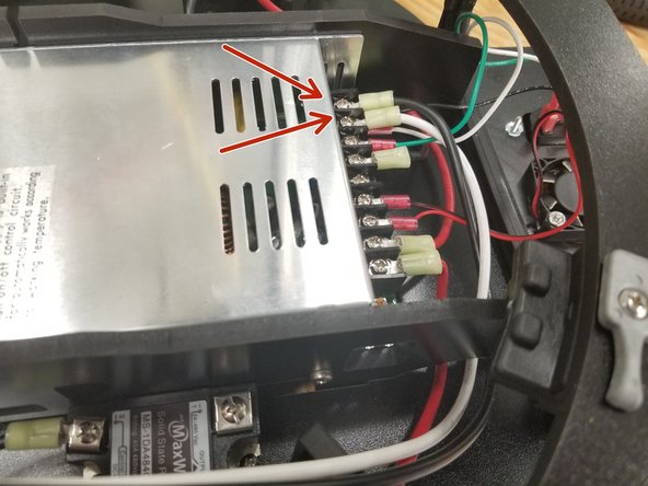
Strip 1/4" off the white and black wires included in the kit, and crimp one ring terminal to one end of the white wire, and one ring terminal to each end of the black wire.
-
Attach the white to N and black to L on the power supply, as shown in the photo.
-
Note: It's recommended to turn the existing red ring terminals upside down when installing them both on the same screw, as shown in the photo.
-
Attach the other end of the black wire to the SSR terminal number 1.
-
-
-
Clean the back of the aluminum heat spreader with alcohol and a paper towel.
-
Peel the backing off of the adhesive on the 58801 Silicone Heater 300mm Dia 350W REV B
-
Apply the heating pad, aligning the three notches with the deeper grooves on the heat spreader, and the white AC wires exiting from the right of the bed, as shown in the photo.
-
-
-
Install the three 58815 Build Plate Clamp for 3mm Boro Glass - Black as shown, using the 30308 M3 - .50 x 18mmL Phillip PH Machine Screw - SS, and three of the 30321 M3 - 0.50 Nylon Lock Nut - SS
-
Tighten to feel, where it's snug but the clamp still turns, firmly.
-
Install the second Nylon Lock Nut and tighten so the first nut won't come loose.
-
Apply the 26659 Kapton Dot 1 inch Dia as shown, under the clamping portion of the bed clamp.
-
It is very important that the kapton dots are applied properly, in the proper location and with little to no air bubbles!
-
-
-
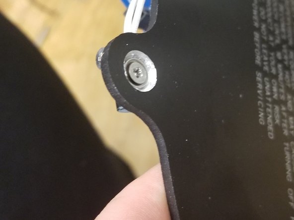
Use the provided 30234 M3 - .50 x 10mm Phillip Flat Head Machine Screw and 30449 #4 SAE Flat Washer - SS to install the 26206 Thermistor Cartridge Mounting Block as shown.
-
Fully insert the 26194 Thermistor Cartridge 100K and gently secure in place using the second included M3 x 10mm flat head screw
-
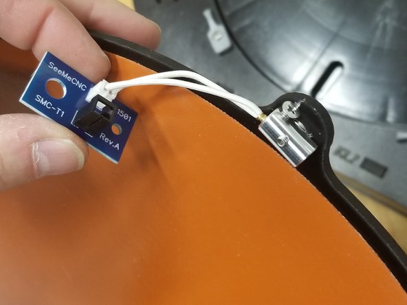
Plug the thermistor into the 51501 Temp Board SMC-T1 thermistor board
-
-
-
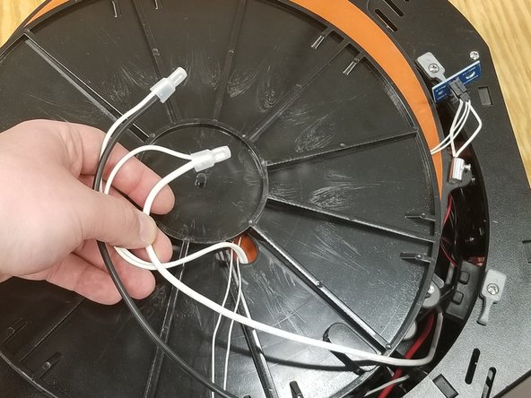
Strip about 5mm of the existing white 26awg thermistor wires exiting the Y tower (that you snipped from the old bed)
-
Be sure the thermistor wires are about 400mm in length from where they exit the Y tower.
-
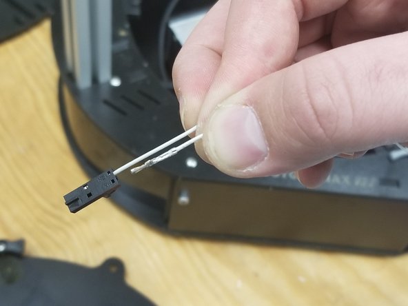
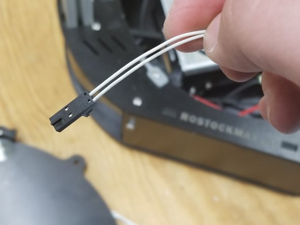
Use the included 26205 SL Crimp Terminals for Molex Latching Connectors and a pair of crimpers to crimp the terminals to the ends of the white wires.
-
House them in the 26202 Molex SL 2 Pin Latching Connector Housing Female, making sure they are inserted all the way with a click.
-
-
-
Strip a 1/4" off of the remaining large black wire from the kit, and crimp a 26178 yellow ring terminal to one end.
-
Attach the ring terminal you just crimped to the SSR in terminal number 2.
-
Strip 10mm off the other end of the black wire
-
Re-install the clear plastic cover on the SSR
-
-
-
Pass the silicone heater wires through the existing plastic bed insulator as shown.
-
Strip the wires from the heater and attach one of the wires to the black wire leading from the SSR terminal number 2, using the 26228 Splice Conn. Insul. 10-16AWG Crimp connector
-
Attach the other white wire to the white wire leading from N on the power supply
-
Plug in the SL connector you installed on the thermistor leads to the SMC-T1 thermistor board
-
Apply electrical tape to the white wires coming from the silicone heater as shown to cover the wires when folded back towards the bed.
-
-
-
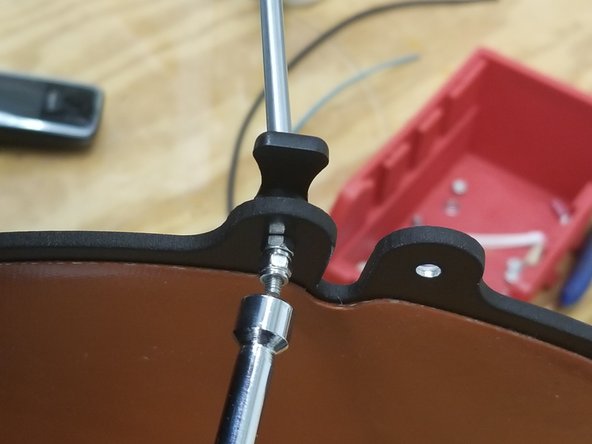
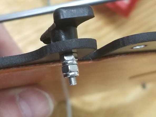
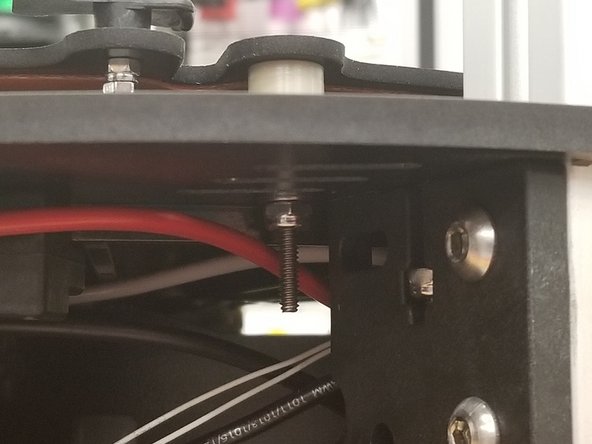
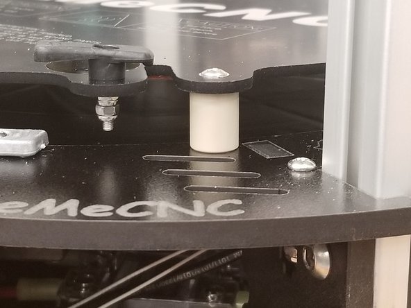
Apply a drop of oil to the tip of the threads on the three 30034 6-32 x 1.75"L Phillip Pan Head Screw - SS
-
Pass the pan head screws through the mounting holes on the heat spreader, then through the 84612 Bed Mounting Post (PEEK), the melamine frame of the printer, then the 30450 #6 SAE Flat Washer - SS with the three remaining 30164 nylon lock nuts
-
-
-
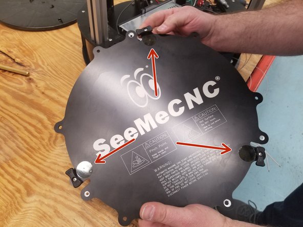
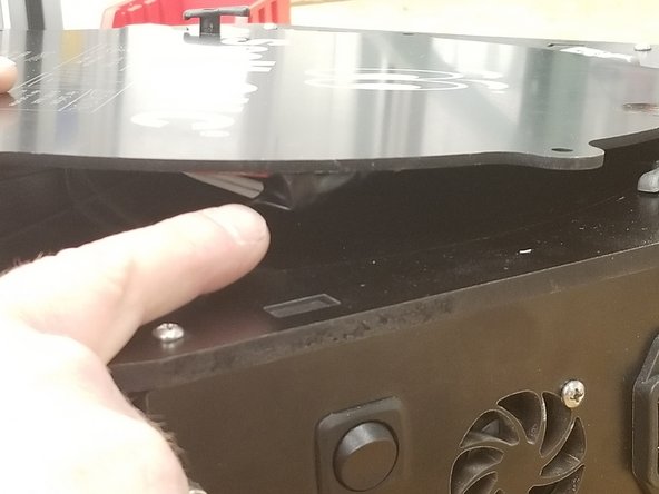
Re-install all the covers on the machine.
-
Plug in the machine and turn it on.
-
Follow these guides and decrease the printer height in your firmware by 23mm:
-
-
DuetWifi
-
-