Difficulty
Moderate
Steps
19
Time Required
- Orion Delta HE280 Hotend Upgrade 19 steps

User-Contributed Guide
This guide is not managed by the site's staff.
Quiz
0
Introduction
Upgrading an Orion 3D printer is not very difficult, but does require basic knowledge of electronics and skills with hand tools. Installing an HE280 may require a heavier duty power supply. It is up to the installer to ensure all AC line voltage is properly enclosed to reduce the risk of electrocution.
-
-
First note that older machines with an ATX computer power supply *might* have trouble keeping up with the HE280 and **might** need replaced with a 12VDC 29A power supply like the one found on our website.
-
If you purchased a fully assembled HE280 hotend, continue. If you purchased your the HE280 hotend in kit form, please Perform that assembly first (beginning with Step 9): HE280 Hotend Assembly
-
Disconnect the power cable from the machine.
-
Disconnect the USB drive from the machine.
-
Set your Orion Delta on a clean work space with plenty of room.
-
-
-
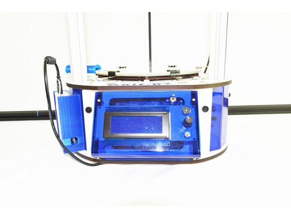
Remove the LCD controller (Front Bezel) from the front of the printer. There are (2) thumb screws attaching it to the printers base.
-
-
-
To remove the RAMBo board from the machine, you will need to:
-
Remove the end-stop plugs from the RAMBo board. You will want to remove them one at a time and label them (on the black 3 pin housing) with a sharpie marker. In order from left to right, these are X Y Z. Be sure to remove them one at a time and label them!
-
You may also need to remove the Stepper Motor 4 pin connectors from the RAMBo board. Just as above, you will need to remove them one at a time and label them upon removing them. They are (from left to right) X Y Z _ E0 _ Be sure to remove them one at a time and label them!
-
You will have enough excess wire length for the remaining wires to get the RAMBo board out of the base.
-
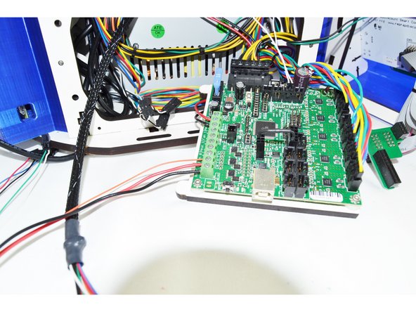
The RAMBo board is mounted to a backer board. You will grasp that backer board on the bottom left and right pull out. The bottom of the RAMBo (and backer) should pull freely and tip out. Once the top ears on the backer board have cleared the top plate of the base, the entire board can be removed.
-
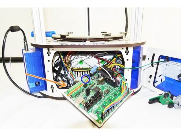
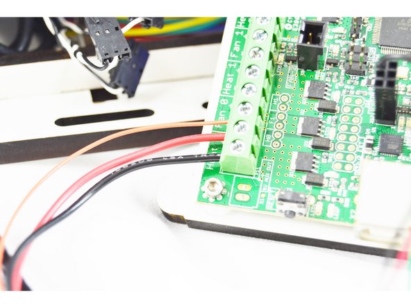
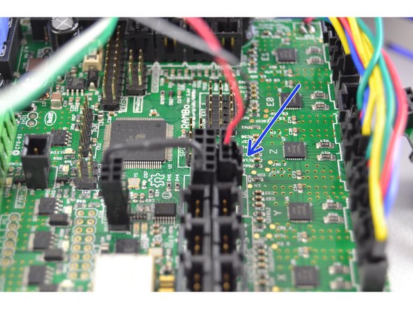
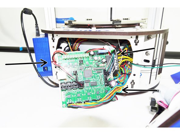
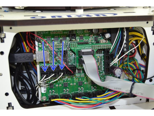
With the RAMBo partially removed and accessible. You will now remove the output wires. You will use a screwdriver to loosen the following terminals: Heat 0, Heat 1, and Fan 0. These are noted in the pic with the orange arrow. DO NOT REMOVE THE WIRES LOCATED AT HEAT 2 (NOTED WITH A BLUE CIRCLE)
-
-
-
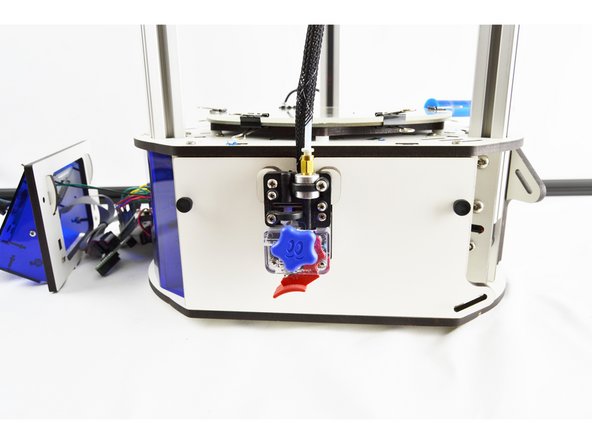
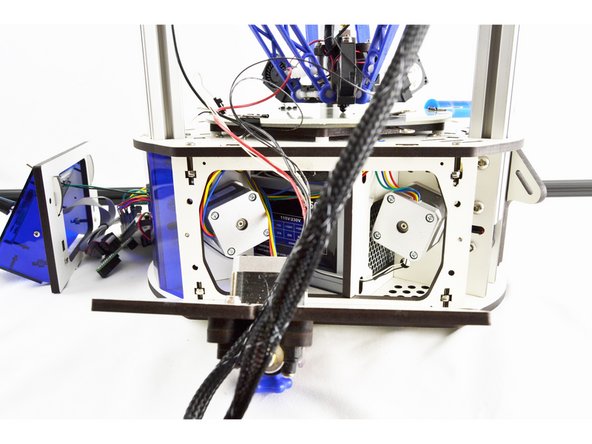
To remove the hotend whip you will first need to remove the side panel with the extruder. This panel is secured with (2) thumb screws.
-
Once the thumb screws have been removed, lay the panel down on its side.
-
Cut the cable tie securing the existing wiring whip to the side panel.
-
-
-
Pull the wires from the existing hotend whip through the base assembly, out the side with the extruder panel (removed)
-
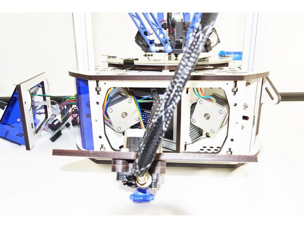
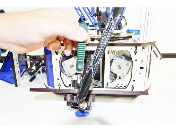
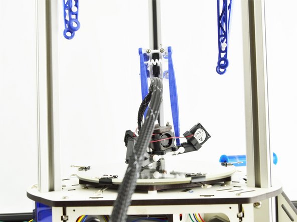
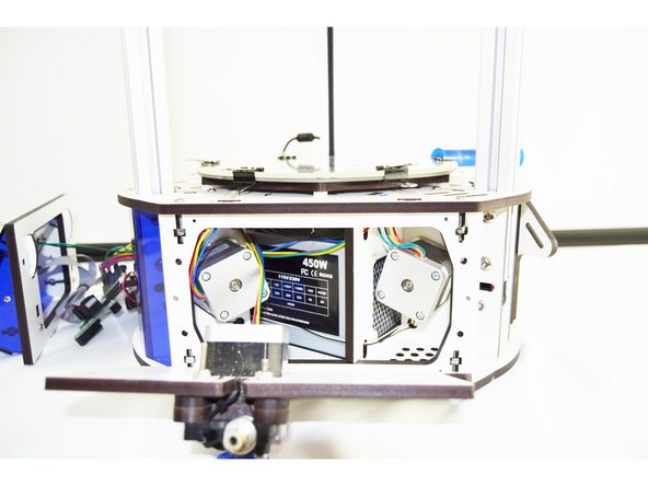
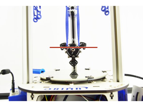
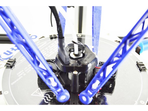
Remove the ball cup arms from the effector platform. To do so, gently pull the ball cup arm off of each ball joint.
-
Perform this operation with all (6) arms.
-
Be sure not to loose the tension springs that go between each set of arms.
-
-
-
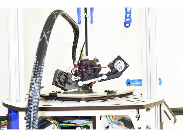
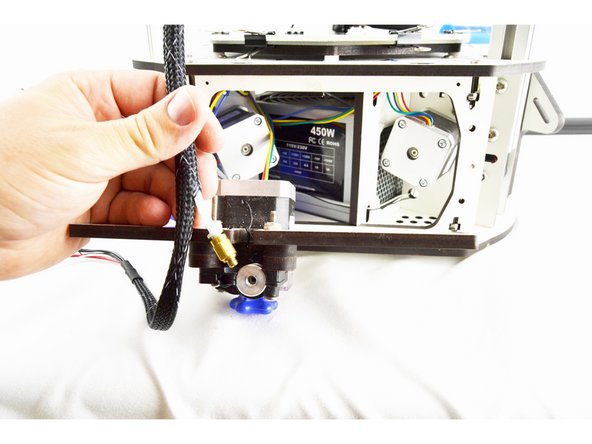
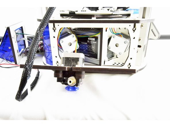
Remove the bowden tube from the extruder.
-
You may find it easiest to remove the PTC fitting from the extruder first and then remove the bowden tube from the fitting as shown in the pictures. If you choose to do it this way, be sure to replace the PTC fitting so it does not get lost.
-
With the bowden tube all 6 arms removed, the effector and whip are now be completely removable from the printer. Remove it and set it aside.
-
-
-
From the front of the printer, insert the new whip (8 pin connector first) through the front of the machine, over the hot end and out the side of the machine with the extruder panel removed.
-
-
-
There are 3 wires that will connector to the top left corner of the RAMBo output terminals. These wires are the 18awg red, 18awg black, and 26awg orange.
-
There are (2) red wires, and (2) black wires in the hot end whip. The 18awg wires are the THICKER wires.
-
Ensure that the screw terminals on the RAMBo are loose before inserting any wires.
-
Insert the black 18awg wire into the Heat 0 negative location
-
Insert the red 18awg wire into the Heat 0 positive location
-
Insert the orange 26awg wire into the Fan 0 negative location
-
-
-
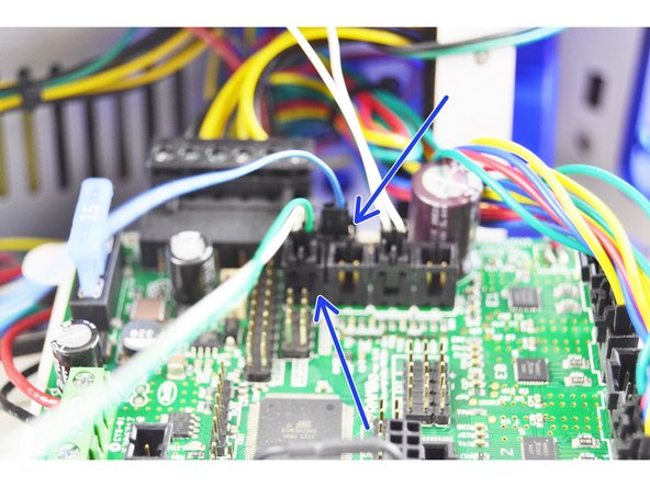
The next connections involve using latching connectors, this means that there is only one way to plug them in. This will ensure that the polarity is correct.
-
Insert the 2 pin latching connector with the green and white wire into the T0 location on the RAMBo board.
-
Insert the 2 pin latching connector with the blue wire into the PS-ON location on the RAMBo board.
-
Insert the 4 pin latching connector with the red and black wire into the I2C location on the RAMBo board.
-
-
-
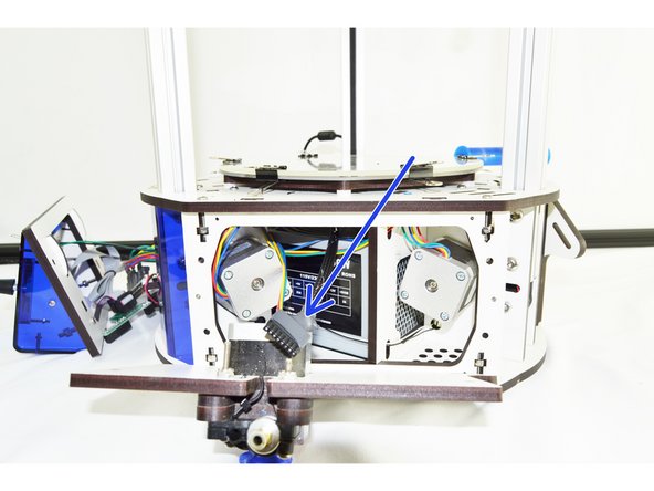
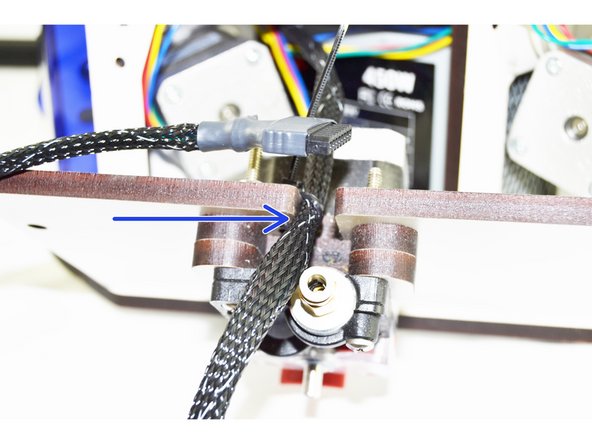
Measure 550mm from the end of the whip with the 8 pin pluggable connector. This is the point that we want to position the whip to secure it to the cover with the extruder motor. The 550mm point should be even with the outside face of the cover (indicated with a blue arrow).
-
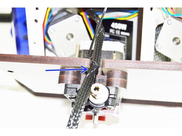
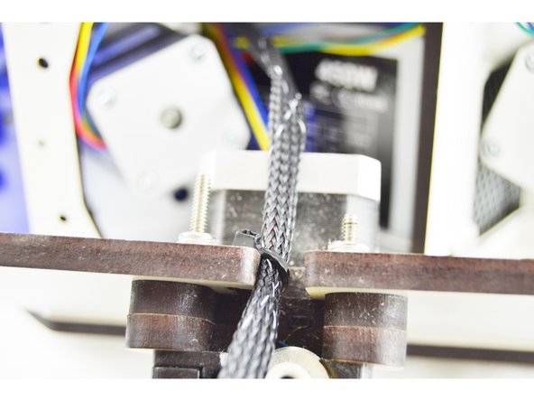
Secure the whip with a cable tie. Tighten the cable tie as much as you can.
-
Clip the excess portion of the cable tie.
-
-
-
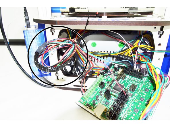
Gently pull any slack wire/whip from the front of the printer. The side panel with the extruder should still be removed, do not pull so much wire/whip that the cover is moved (we want to be left with enough slack that the cover can be removed in the future is maintenance is required.
-
Coil the wire once and add a cable tie to secure it. (Shown in the image with a black circle)
-
Cut the excess portion of the cable tie.
-
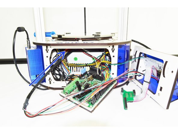
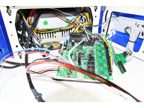
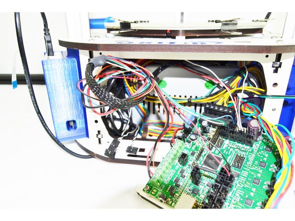
Route the wires on either side of the RAMBo board as shown in the picture.
-
No wires can be routed over the top of the RAMBo board. This will not permit the RAMBo to have enough room to be mounted back into the printer.
-
-
-
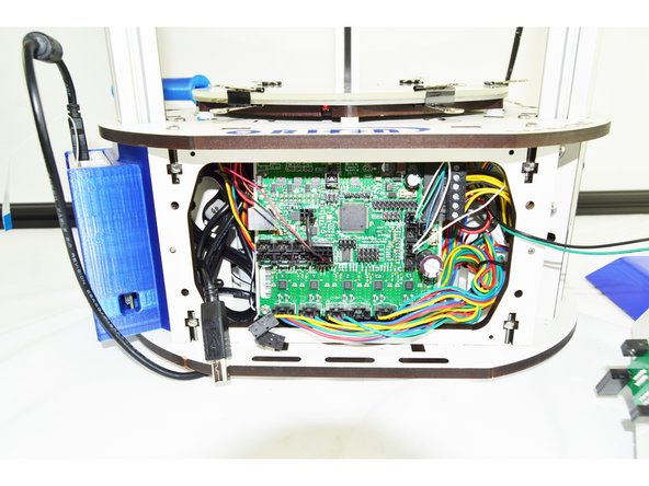
The RAMBo board will be installed just like it came out of the machine.
-
You will need to first angle the RAMBo board and insert the top into the base of the printer. You need to get the two tabs to align with the slots on the top plate of the base.
-
Once you have those tabs starting to engage in the slots, you can push on the bottom of the RAMBo board to get it to seat into the board holder legs on the bottom plate of the base.
-
DO NOT FORCE THE RAMBo BOARD. IF YOU ARE FEELING SIGNIFCANT RESISTANCE WHEN INSERTING THE RAMBo, FIND ANY WIRES THAT MAY BE INTERFERING.
-
After you have the RAMBo board back in place, install any additional wires that were removed. ie end-stop wires, motor wires, USB, LCD adapter, etc.
-
Be sure that when installing end-stops and motor wires that you pay particular attention to the labels and get them installing in the correct location. The end-stops should be installed in the MAX location and the motors should be installed in the X Y Z _ E0 _ locations.
-
Install the LCD bezel and secure with the original thumb screws.
-
-
-
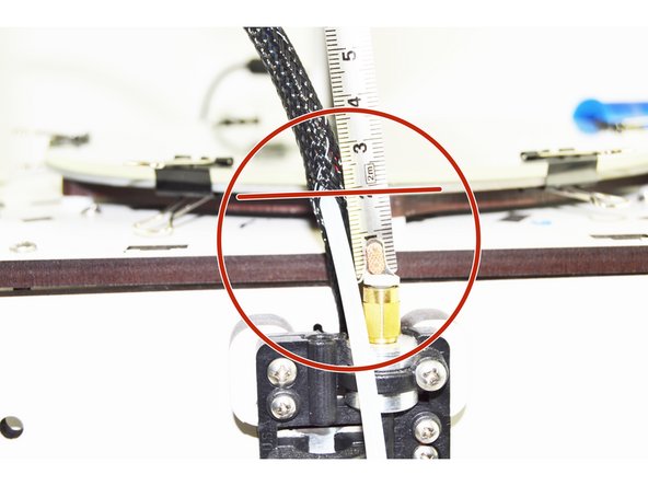
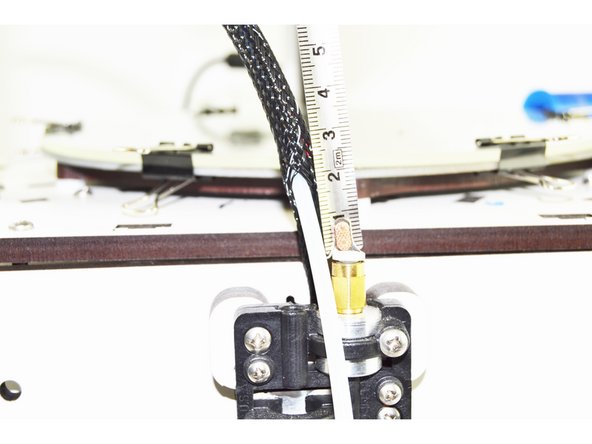
Measure 20mm from the top of the PTC Fitting (this is universal between EZ & EZR Struders)
-
This is the entry point of the PTFE tube into the whip. You will need to compress the mesh loom at that point in order to separate it enough to get the PTFE enough room to gain access.
-
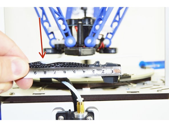
Once you have that PTFE started you will feed it through the whip until you are 200mm from the end of the whip (measured from the end of the 8 position pluggable connector)
-
At that 200mm mark the PTFE will exit the whips mesh loom. Pull out any remaining slack in the PTFE tube.
-
-
-
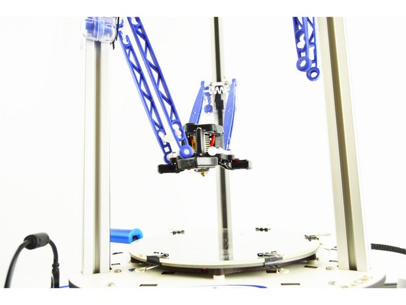
Just like you removed the old hotend, you are going to install the new hotend.
-
Start with the Z axis tower arms. You are going to connect these arms to the ball joint that are located directly in front of the hotend fan so that when hanging loose as in the image, you can read SeeMeCNC from left to right.
-
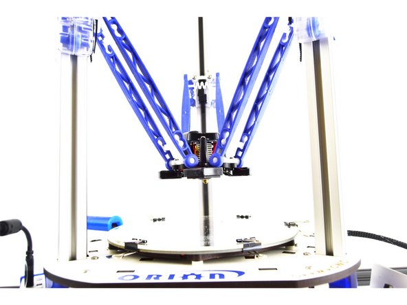
Connect the remaining ball joint arms.
-
Make sure that the tension springs are in place.
-
-
-
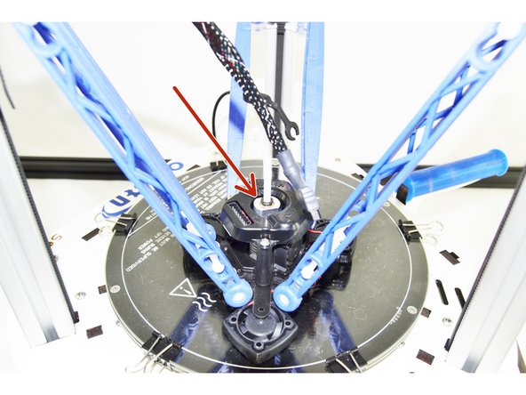
Slide one of the Lanyward PTC Clips onto the Bowden (PTFE) Tube.
-
Insert the Bowden (PTFE) Tube into the top of the hot end. Press the tube down until you feel it seat in the bottom of the hot end. Press the hot end effector down so the nozzle is against the glass plate and give the Bowden (PTFE) Tube one more good push to ensure that it is seated fully.
-
-
-
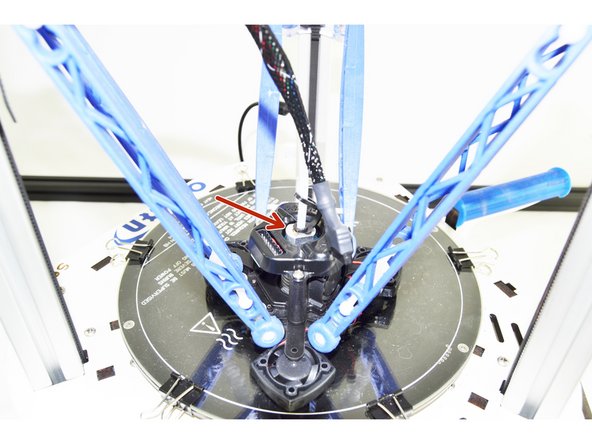
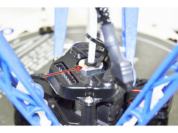
With the Bowden (PTFE) Tube pressed down, you will now lift up on the black ring in the top of the hot end.
-
Insert the PTC Lanyard onto the black ring in the top of the hotend. This will secure the Bowden (PTFE) Tube and prevent it from being able to work its way out of the hot end.
-
It is critical that the PTFE is fully seated in the hotend. If it is not it can result in the hot end jamming.
-
-
-
You will now need to trim the PTFE length to fit the extruder.
-
For the older EZStruder you will be trimming the PTFE so it seats in the bottom of the brass PTC fitting.
-
For the newer EZR Struder, you will be trimming the PTFE so it seats in the bottom of the filament path in the EZR Struder body (Approximately 40mm from the end of the extruder).
-
YOU MUST NOT USE SCISSORS. YOU MUST USE A SHARP BLADE SUCH AS A UTILITY OR HOBBY KNIFE.
-
Measure Twice Cut Once!
-
Seat the PTFE tube in the extruder once you have it cut to length.
-
-
-
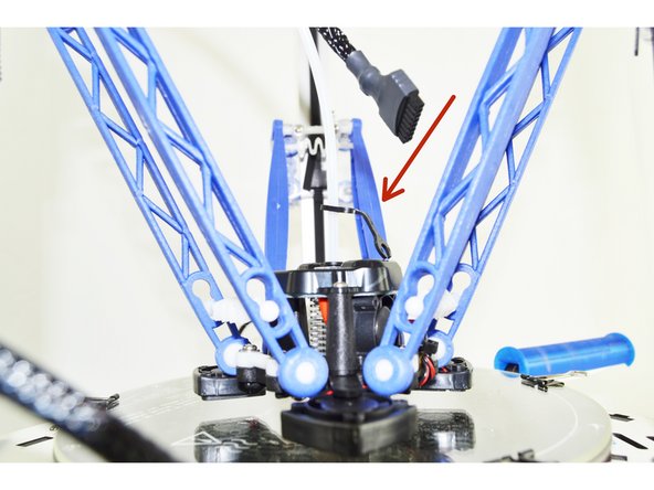
We saved the most difficult step for last. Plug the 8 position plug into the top of the hotend. This plug is keyed so pay particular attention to the orientation and do not force it if it is not going.
-
-
-
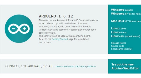
Your new HE280 Hotend will not work until the firmware has been updated to .92
-
We have a Separate guide to walk you through the steps of updating firmware. Please go to: Firmware Uploading and complete that guide.
-