
Difficulty
Moderate
Steps
23
Time Required
- Droplit v2 Frame Assembly 23 steps

User-Contributed Guide
This guide is not managed by the site's staff.
Quiz
0
-
-
Locate the Projector Plate, Projector Joining Plate, (3) 6-32 x 1" Phillip Pan Head Screws, (3) Nylon Lock Nuts, (3) Plastic Bearings, (4) Legs, (4) Rubber Feet, (4) 10-32 x 5/8" Pan Head Nylon Screws, and (4) 10-32 Finish Nuts.
-
-
NOTE: Be sure to get the correct orientation of the Projector Plate (the engraved text indicates the TOP) and Projector Joining Plate.
-
Tighten all fasteners.
-
-
-
Locate the Base Plate, (4) 6-32 x 1" Phillip Pan Head Screws, (4) Nylon Lock Nuts, (4) Legs, (4) Rubber Feet, and (8) Leg Standoffs.
-
-
NOTE: Be sure to get the correct orientation of the Base Plate (the engraved lines running from the left to right near the front center of this plate indicates the TOP)
-
-
-
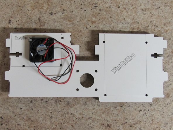
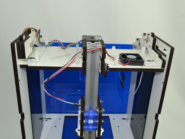
Locate the Motor Plate and 40mm fan.
-
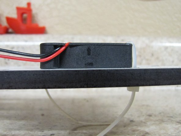
You will be mounting the 40mm fan to the top of the Motor Plate using 2 zip ties, one on the upper left and one on the lower right corners of the fan.
-
The fan should be mounted in such that the air will flow upwards (see image) and the wires will come off of the top of the fan and towards the back of the Motor Plate.
-
-
-
Note: The fan was installed in Part 1 of Prepping the Motor Plate.
-
Locate the (7) Board Supports and (7) #6 x 1/2"L Phillip Pan Head Screws.
-
You will attach the Board Supports to the Motor Plate as shown in the animation.
-
You can fully tighten these as you go.
-
-
-
Locate the following Parts: Left Side Panel, Right Side Panel, Base Plate, Vat Plate, Motor Plate, (2) Acrylic Side Windows, (10) 6-32 x 1" Phillips Pan Head Screws, and (10) 6-32 Nylon Lock Nuts.
-
NOTE: The Left Side Panel has a protrusion that extends out from the front edge and the Right Side Panel has 3 slots in the front that cut back towards the side window.
-
NOTE: Pay particular attention to the orientation of the remaining parts in the assembly animation.
-
Assemble the mid section parts to the Left Side Panel first and then to the Right Side Panel.
-
Do NOT fully tighten the screws at this time.
-
-
-
-
Locate the Upper Plate Mount Right, Upper Plate Mount Left, Barrel Connector Hold-down, (4) 6-32 x 1" Phillips Pan Head Screws, and (4) 6-32 Nylon Lock Nuts.
-
Attach the Upper Plate Mount Right and Left pieces according to the animation.
-
NOTE: The orientaion of these pieces is critical. When installed their labels of RIGHT / LEFT should still be visible.
-
-
-
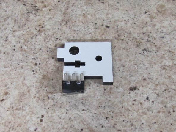
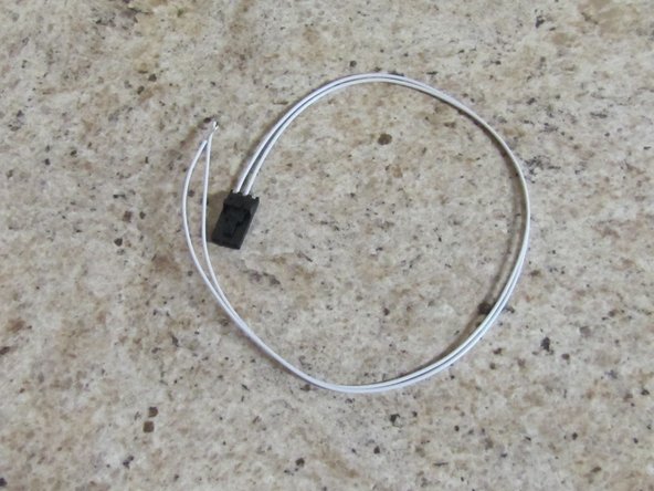
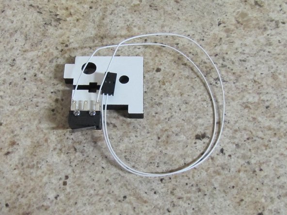
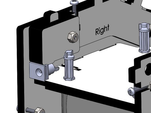
Locate (1) of (2) Upper TSLOT Mounts, (2) 2-56 x 5/8" Pan Head Machine Screws, (2) 2-56 Finish Nuts, and Pre-terminated End Stop Wires.
-
Attach the Limit Switch to the Upper TSLOT Mount as shown in the picture using the 2-56 hardware.
-
Solder the End Stop Wires (two white wires with a 3 pin connector on one end) to the outer two legs of the limit switch as shown in the image.
-
-
-
Since we already have the soldering iron heated up, lets get the rest of the solder connections out of the way.
-
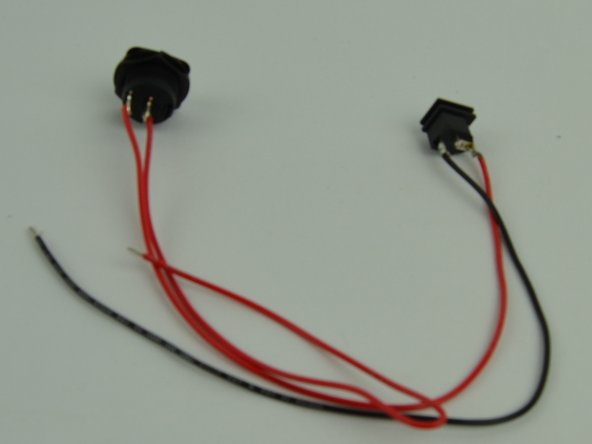
Locate the (2) 18awg x 300mm RED wires, (1) 18awg x 300mm BLACK, (1) Barrel Jack Connector, and (1) Rocker Switch
-
Solder both of the red wires to the legs of the Rocker Switch
-
Solder the other end of one of the red wires to the top (next to the round) of the barrel connector.
-
Solder the black wire to the bottom of the barrel connector.
-
NOTE: The middle pin on the barrel connector is not used.
-
Your finished product should look like the image on the left. Set it aside for installation later.
-
That is all the soldering for the entire kit.
-
-
-
Locate the (2) Upper TSLOT Mounts, (2) Lower TSLOT Mounts, (4) 1/4-20 x 1/2" Button Head Cap Screws, and (4) TSLOT Nuts.
-
Attach the 1/4-20 x 1/2" Button Head Cap Screws, and TSLOT Nuts to the Upper and Lower TSLOT Mounts first,
-
DO NOT TIGHTEN THE SCREWS BEYOND JUST GETTING THE THREADS TO ENGAGE.
-
Place the Upper and Lower TSLOT Mounts on the frame assembly you have been working on as shown in the animation. The Upper TSLOT Mount with the limit switch attached will be installed on the LEFT side. You will see the notches in the motor plate which are clearance for the 2-56 screws.
-
-
-
-
Locate the Back Plate, (6) 6-32 x 1" Pan Head Phillips Screws, and (6) 6-32 Nylon Lock Nuts.
-
Install the Back Plate on the assembly
-
Note: By installing the Back Plate this will square up the frame of the machine. You will removing this panel in future steps for further part installation.
-
Tighten the 6 screws that join the Left / Right Panels to the Back Plate
-
Tighten the screws that join the Left / Right Side panels to the Base Plate, Vat Plate, and Motor Plate (10 total screws)
-
-
-
-
Locate the TSLOT and the Carriage Assembly (Assembled in a previous section)
-
Begin by installing the TSLOT down through the top of the Upper TSLOT Mounts. You must have the TSLOT nuts Oriented so that they will go into the slot of the TSLOT.
-
After the TSLOT has passed through Motor Mount Plate by approximately 4", align the Carriage Assembly and gently push the TSLOT down through the carriage.
-
Continue to pass the TSLOT down into the Lower TSLOT Mounts until it is flush with the botto surface of the VAT Plate.
-
Tighten the 1/4 -20 x 1/2" Button Head Screws fully securing the TSLOT.
-
-
-
-
Locate the M10 x 2 x 200mm Trapezoidal Lead Screw, 5mm Shaft Coupler, (4)M3 - .5 x 3mm Set Screws, and M3 Allen Wrench
-
Insert the Set Screws into the Shaft Coupler. Tighten the set screws approximately half their length into the Shaft Coupler.
-
Attach the 5mm Shaft Couple to the Trapezoidal Lead Screw. It is best to twist either component while inserting the two items together.
-
Seat the Shaft Couple Fully onto the Trapezoidal Lead Screw and tighten the (2) set screws completely.
-
Insert the Trapezoidal Lead Screw through the hole in the Motor Plate and rest it on the Anti-Backlash nut on the carriage.
-
Place downward pressure on the Anti-Backlash collar and at the same time turn the Trapezoidal Lead Screw clockwise while pushing downwards to engage the threads on the two components.
-
Once engaged, continue turning the Trapezoidal Lead Screw until you have approximately 2" extended below the bottom of the carriage assembly.
-
-
-
-
Locate the NEMA 17 Stepper Motor and (4) M3-.5 x 10mm Phillip Pan Head Screws.
-
Orient the NEMA 17 Stepper Motor with the wires exiting the body of the motor to the right. Attach the motor to the Motor Plate.
-
Tighten the screws completely.
-
Lift the Carriage Assembly and Trapezoidal Lead Screw(set screw facing the front of the machine), inserting the stepper motor shaft (flat facing the front of the machine) into the shaft coupler.
-
With this in position, tighten the (2) set screws onto the stepper motor shaft. ENSURE THAT ONE OF THE SET SCREWS IS LANDING ON THE FLAT OF THE STEPPER MOTOR SHAFT.
-
Turn the Trapezoidal Lead Screw clockwise until you hear the limit switch engaged by the carriage.
-
Carefully lay the machine on its back and tighten the (3) #4 Phillips Pan Head Screws into the Anti-Backlash Nut. ENSURE THAT YOU ARE NOT APPLYING ANY PRESSURE TO THE TRAPEZOIDAL LEAD SCREW. YOU WANT THE LEAD SCREW TO SELF ALIGN WITH THE ANTI-BACKLASH NUT AND SECURE IT IN THAT POSITION.
-
-
-
-
Locate the Upper Hinge Mount, (3) Hinges, (4) 6-32 x 1" Pan Head Machine Screws, (4) 6-32 Nylon Lock Nuts, (3) 2-56 Finish Nuts, and (3) Plastic Bearings.
-
Insert the (3) 2-56 Finish Nuts into the Hinges (similar to how you inserted the 6-32 Nylon Lock Nuts into the but traps for the rest of the frame).
-
Attach the components as shown in the animation, starting with the Hinge Mount.
-
NOTE: You should not over-Tighten the the three screws that act as the pivots or else the door will not easily open / close. Loosen these screws if you find that he hinge does not easily open / close.
-
-
-
Locate the Front Acrylic Door, Door Handle, and remaining 2-56 Finish Nut, and (4) 2-56 x 5/8" Phillips Pan Head Screws.
-
Insert the 2-56 Finish Nut into nut trap in the Door Handle.
-
Install the Acrylic Door as shown in the animation. Secure the door with the 2-56 x 5/8" Phillips Pan Head Screws.
-
Attach the Door Handle to the Acrylic Door as shown in the animation.
-
TO PREVENT CRACKING THE ACRYLIC DOOR, DO NOT OVER-TIGHTEN THE SCREWS.
-
-
-
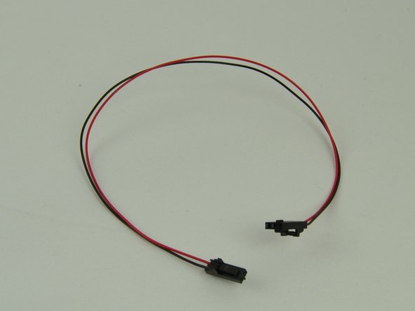
Locate the Mini-RAMBo board, Raspberry Pi 3 board. Rocker Switch / Barrel Connector (previously soldered), and 5v wire harness.
-
Remove the pack panel from the machine (don't forget to remove the 6-32 x 1" Phillips Pan Head Screws holding it in place).
-
You will be Installing l the Mini-RAMBo and Raspberry Pi in the top of the DropLit. You must have the Board Supports in the correct orientation so that the board will slide into the board retention area.
-
For the Mini-RAMBo, the board supports closest to the back of the Droplit v2 will be catching the sides of the board and the Board supports closest to the front of the machine will be catching the corners of the board.
-
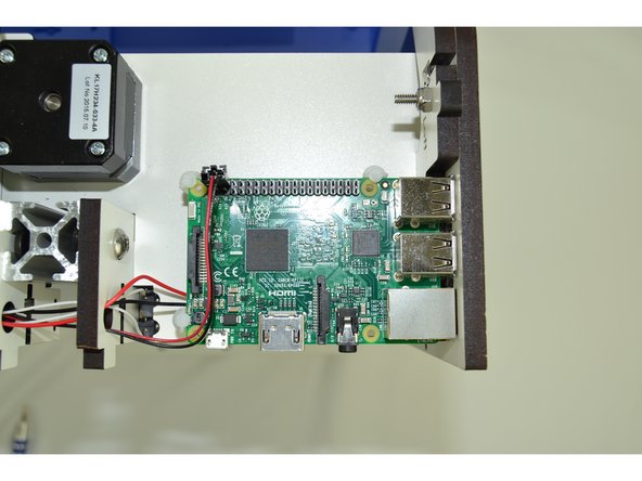
For the Raspberry Pi 3, two board supports will be catching the edges of the board and one will be catching the corner.
-
The animation shows how the boards are oriented and inserted into the machine. The pictures in the next step(s) show how to "tame" the wires and where to connect them.
-
-
-
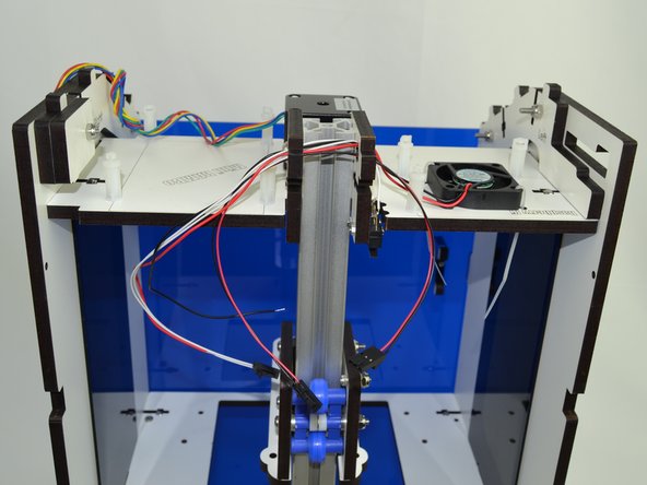
Route the fan and endstop wires through the holes located in the top corner of the Upper TSLOT Mounts.
-
Route the 5v Wire Harness through the same holes. The three pin connector needs to be on the side closest to the fan.
-
-
-
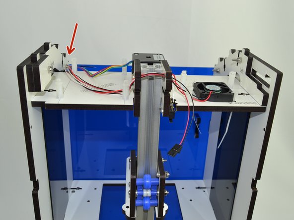
Tuck the wires on the side that the Mini-RAMBo will go next to the post as indicated. This will keep the wires out of the way of the board support while inserting the board.
-
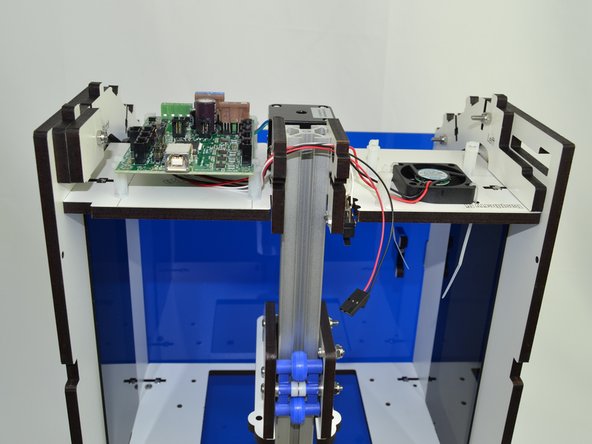
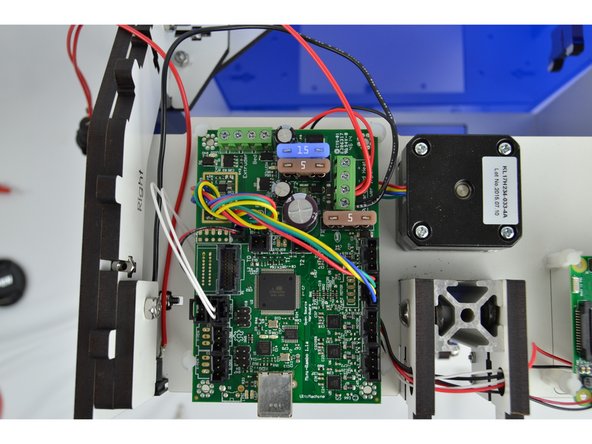
Slide the Mini-RAMBo board into position.
-
-
-
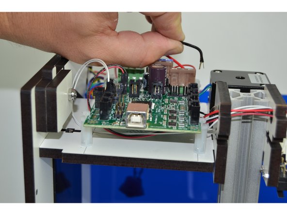
Make the following wire connections:
-
18awg RED wire from the Rocker Switch & RED fan wire connects to Power Input - Primary - Positive (+)
-
18awg BLACK wire from the Barrel Connector & BLACK fan wire connects to Power Input - Primary - Negative (-)
-
NEMA 17 Stepper Motor wires will connect to the Z axis driver. (NOTE: The red wire should be closest to the 15amp fuse)
-
End Stop wires connect to the Z-Max
-
2 pin connector from the 5v Wire Harness will connect to X1 on the Mini-RAMBo and the 3 pin connector will connect to pins 4 &6 on the Raspberry Pi (Pi pinout: http://tinyurl.com/mtwp3kj) (NOTE: the 2&3 pin connectors MUST BE PLUGGED IN BASED ON THE ORIENTATION IN IMAGE)
-
-
-
Push the Barrel Connector into the pocket show in the image. Once the Back Plate is installed this will fully constrain the connector.
-
You are now ready to re-install the the Back Plate. Use the (6) previously used 6-32 x 1" Pan Head Phillips screws plus two additional of the same type of screw through the Base Plate.
-
-
-
Locate the Skylight, Acrylic Skylight and (4) 6-32 x 1" Pan Head Phillips Screws.
-
Lay the Acrylic Skylight into the recesses on the sloped portion of the frame.
-
Install the Skylight and secure using (2) 6-32 x 1" Pan Head Phillips Screws. Fully Tighten
-
You can set the Top Plate in position but do not fully tighten. We must image the SD card and install it in the Raspberry Pi 3 before the top is fully buttoned up. (This will be done in a separate Guide). After that SD has been installed you can secure the Top Plate.
-
-
-
-
Using the supplied 10-32 Knurled Thumb screws, you will now install the Mirror Mount and VAT.
-
The Mirror Mount should point the Mirror toward the back of the printer and is secure to the Base Plate with (2) 10-32 Knurled Thumb screws
-
The VAT should have the spill spout in the back of the printer.
-
There are (3) 10-32 Knurled Thumb screws that go up through the VAT Plate that are used to level the VAT. (2) additional 10-32 Knurled Thumb screws will secure the VAT.
-
Cancel: I did not complete this guide.
2 other people completed this guide.
