-
-
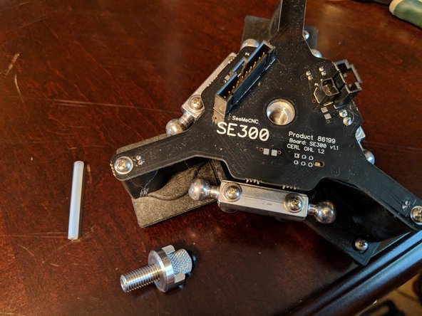
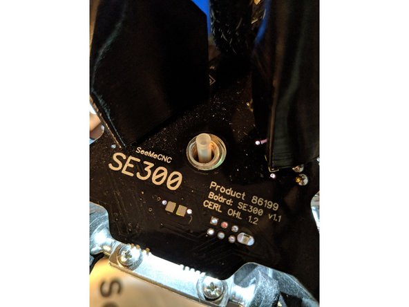
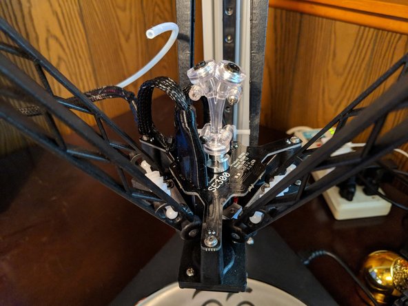
On the Y tower remove the black plug on the face of the extrusion.
-
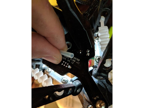
Cut a length of filament about 4 feet long. Long enough to reach from the hole in the extrusion to the top of the machine with extra.
-
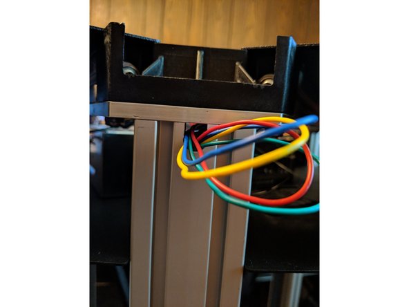
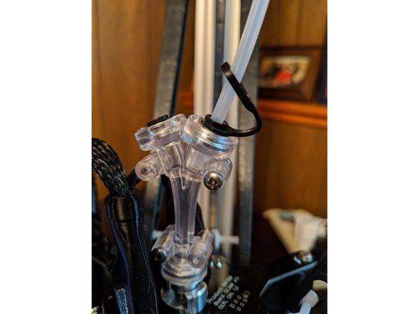
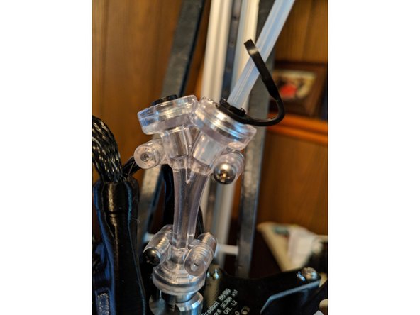
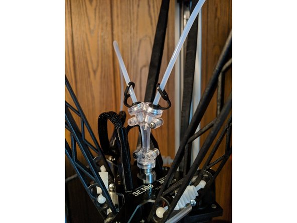
Feed the filament into the hole on the side of the extrusion and up to the top and out as shown in Pictures 2 and 3.
-
-
-
Tape the end of the motor wires included in the kit to the end of the filament as shown in Figure 1.
-
Make sure to cover the metal plugs at the end of the wire so it will not catch on anything inside the tower.
-
While feeding the wires from the bottom, pull the filament out from the top slowly until you pull the wires out of the top as shown in Figure 2.
-
After you have pulled a length of the wires out of the top, you can remove the tape from the wires and filament. Discard the filament.
-
-
-
Looking where the wires exit the top of the tower, you will now feed the wires through to the inside of the top of the machine. See Figure 1.
-
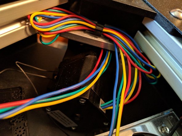
With all 4 motor wires fed through, pull them all the way through into the top of the machine as seen in Figure 2.
-
-
-
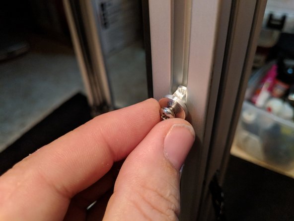
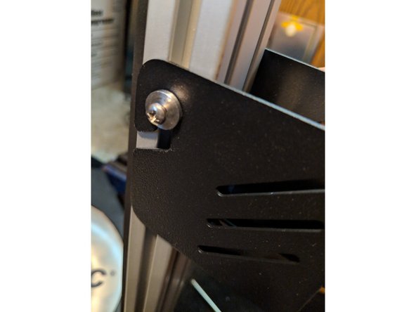
Approximately 2.5" above the hole, Insert one of the two extruder hangers on the left side of the rail when viewing it from the outside as shown in Figure 1.
-
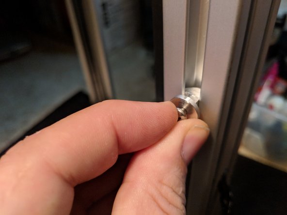
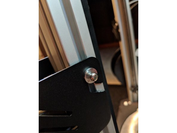
Rotate the hanger clockwise to lock it in the rail and tighten the screw as shown in Figure 2.
-
-
-
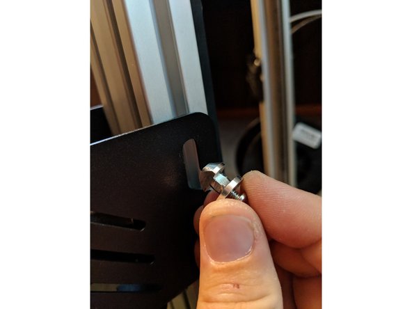
Place the extruder on the hanger you installed in the previous step as shown in Figure 1.
-
On the right side of the extruder, insert the other hanger through the extruder mount and into the Y-Tower extusion. Rotate it clockwise and tighten the screw to lock it in place as shown in Figure 2.
-
You can now pull any excess wire from the top while feeding from the bottom at the extruder to take up any remaining slack.
-
-
-
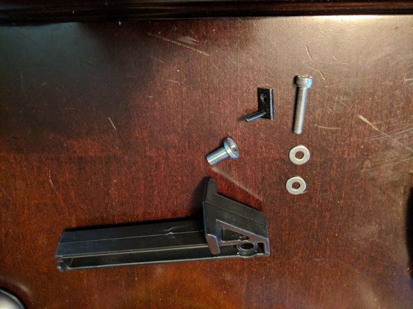
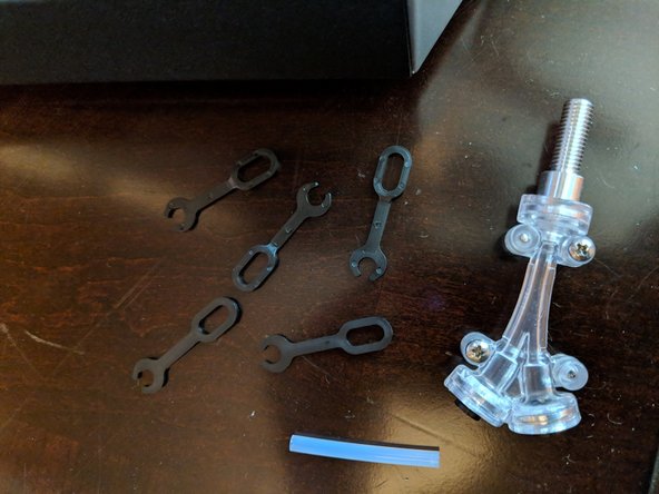
For this step we will need the Spool hanger (large injection molded plastic piece), Stainless steel insert, Threaded screw and 2 washers.
-
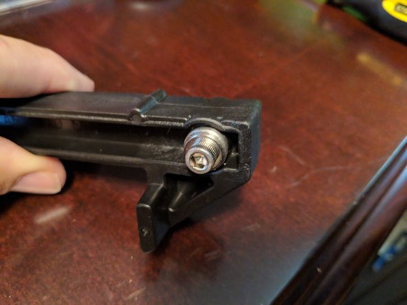
First insert the stainless steel insert into the spool hanger in the side shown in Figure 2.
-
Place one washer on the threaded screw and insert the screw into the stainless steel insert as shown in Figure 2.
-
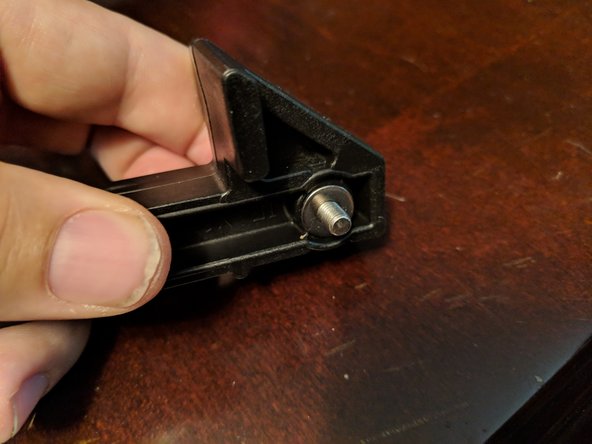
Place one washer on the other side of the spool hanger on the threaded screw as shown in Figure 3.
-
-
-
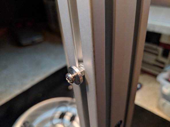
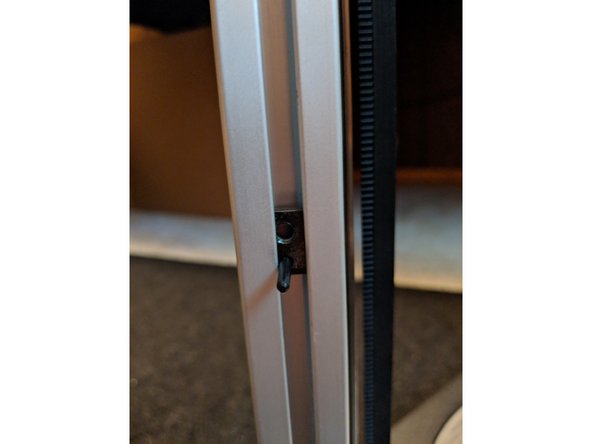
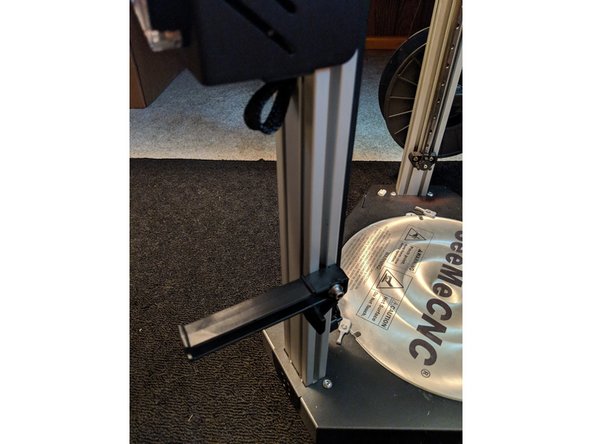
Approximately 6 inches from the bottom of the extruder mount, take and insert the threaded t-nut adapter into the extrusion as shown in Figure 1.
-
Line the screw up with the threads on the t-nut and tighten the spool hanger to the extusion as shown in Figure 2 and Figure 3.
-
-
-
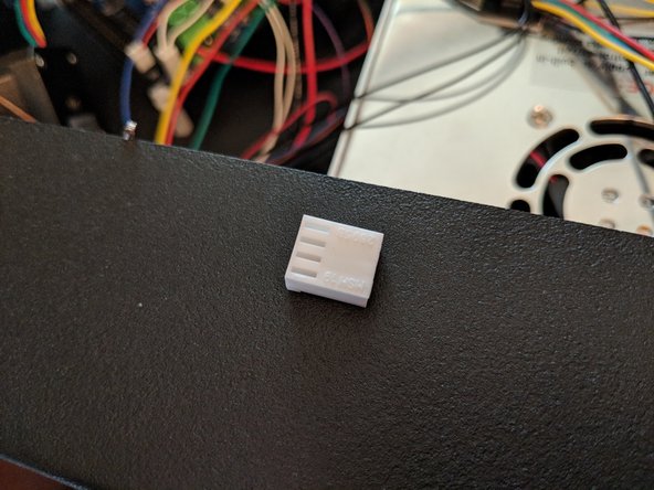
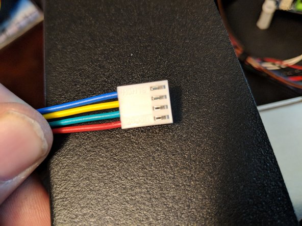
Locate the 4 pin connector that was included in the kit.
-
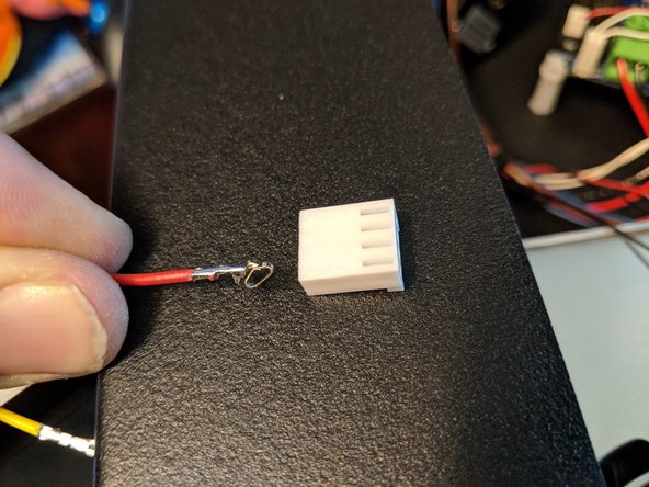
In the top of the machine take the 4 wires from the new extruder motor and insert the wires into the connector.
-
The connectors have a small tab that sticks up from them. This tab should be inserted fully until it latches into the window of the 4 pin connector. It is very important that this tab is fully seated into the plug!
-
Insert the wires in the order as shown in Figure 3. You can also see the tab on the wires fully seated in this photo.
-
-
-
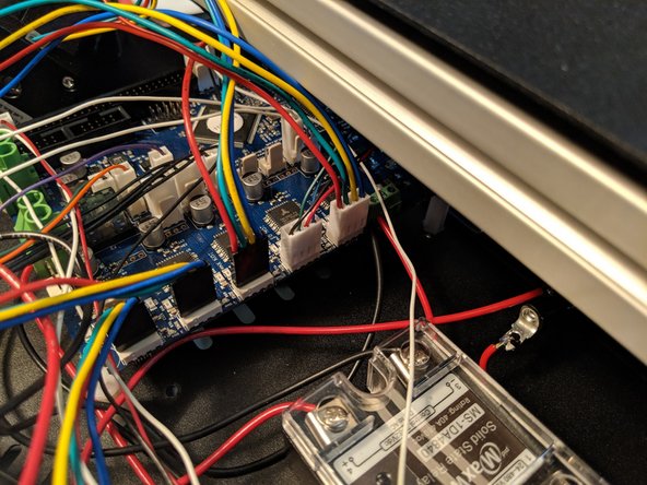
Plug the second extruder into the 5th position on the Duet Electronics board.
-
As seen in the picture the motors are in order from left to right: Z Motor, Y Motor, X Motor, First Extruder, Second Extruder (the one you are installing).
-
-
-
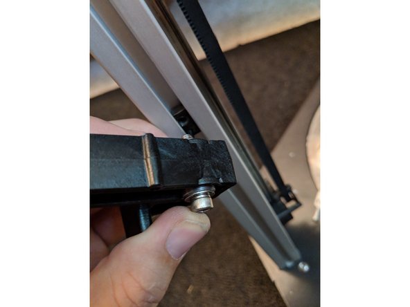
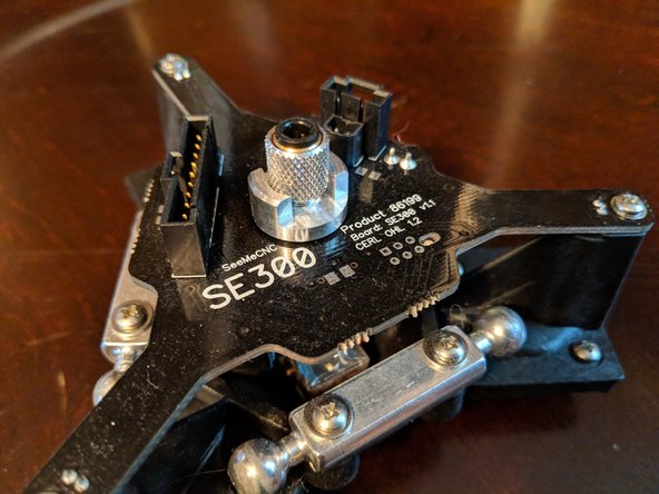
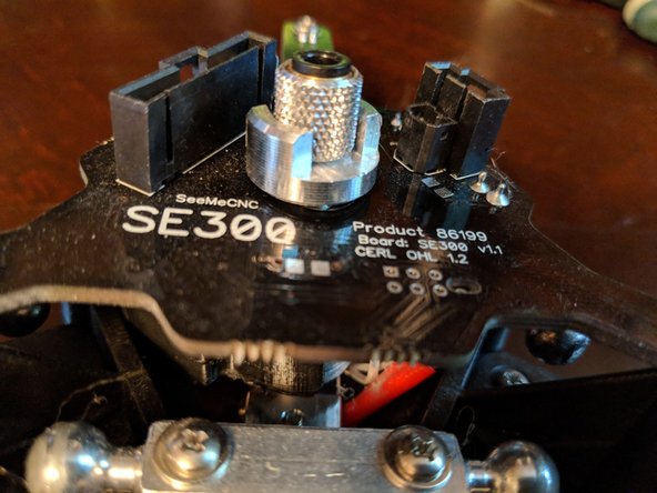
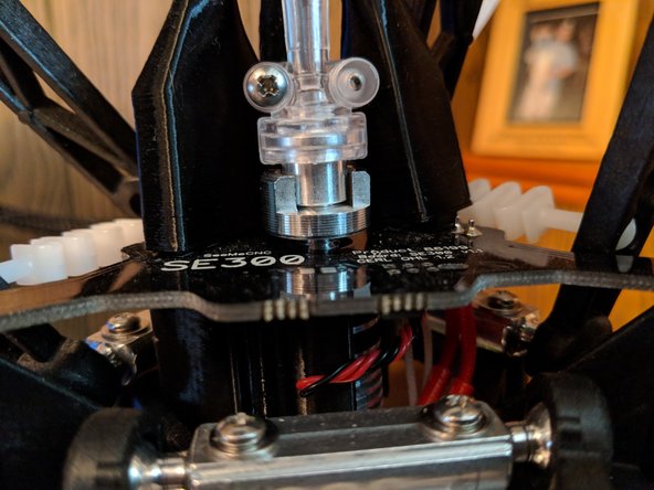
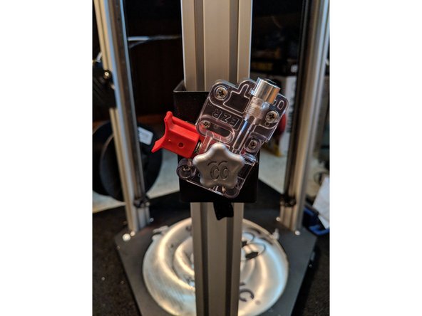
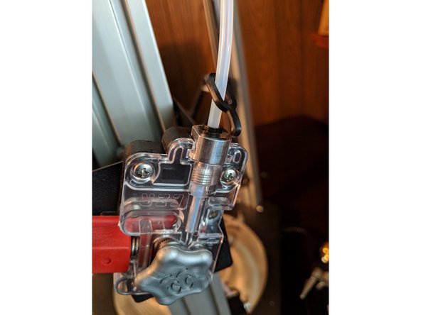
Loosen the collar below the knurled thumb screw that holds the PTFE tube on. See Figure 1 and Figure 2.
-
Remove the adapter from the hotend by unscrewing it and remove the old PTFE liner from the hotend. Figure 3.
-
-
-
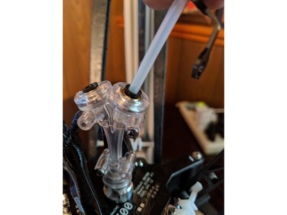
Locate the new PTFE liner that came in the kit. (Figure 1)
-
NOTE Figure 2! The liner has a taper on one side of it, you MUST have this taper facing up towards the circuit board side of the hotend!
-
Insert the PTFE liner with the taper side up into the hotend. See Figure 3.
-
-
-
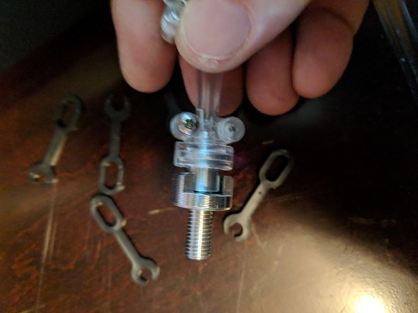
Locate the 2 into 1 adapter and the locking collar from the kit.
-
Install the collar onto the 2 into 1 adapter as shown in Figure 1.
-
Install the 2 into 1 adapter into the hotend until you feel resistance.
-
DO NOT OVERTIGHTEN when screwing the adapter into the hotend. You want to install it until you feel resistance, then go up to 1/2 turn beyond that but NO FURTHER.
-
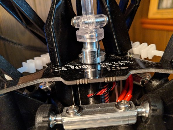
See Figure 2 to see approximately how much the adapter will be screwed into the hotend.
-
Secure the adapter to the hotend by tightening the locking collar down to the circuit board and use a pair of pliers to secure it tight. See Figure 3 to see the locking collar tightened down.
-
-
-
Locate the PTFE tube included with the kit. This PTFE tube will be long enough to use on both extruders.
-
Using a razor blade or hobby knife, cut the PTFE tube in half making the cut as straight as possible to make the tube ends right angles.
-
You should now have 2 approximately equal length pieces of PTFE tube.
-
Insert the first PTFE tube into the 2 into 1 adapter as shown in Figure 1
-
Install the locking clip included with the kit as shown in figure 2.
-
If you look at Figure 2 you can see that after the locking clip is installed, the PTFE tube is not fully seated into the adapter. After the clip is installed, press the PTFE tube further into the adapter to fully seat it. See Figure 3 for fully seated tube.
-
-
-
Put another locking clip on the PTFE tube, and insert the tube into the extruder.
-
Install the locking clip as you did on the previous step to lock the tube in place.
-
As before, after the clip is installed, press the tube further into the extruder to fully seat it.
-
-
-
For your main extruder you can either use the tube that was previously installed in your machine and have a spare or replace it with your remaining PTFE tube.
-
You will route the tube the same way as previously through the wire loom to link the wires with the tube.
-
Install the tube just like the previous steps by inserting into the 2 into 1 adapter with locking clips and into the X Tower extruder with the locking clip.
-
-
-
Once the mechanical installation is complete, You need to enable the second extruder in the Duet configuration.
-
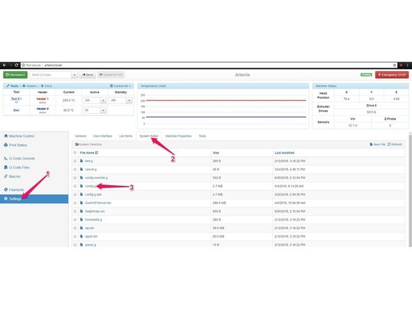
Open the Duet Web Control. Go to Settings, then go to System Editor. Click on config.g to edit it. (Pic 1)
-
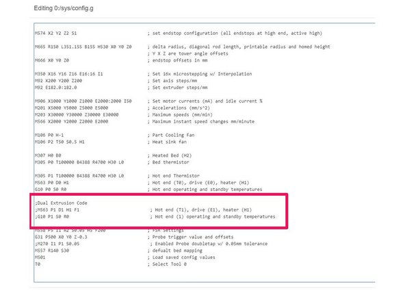
Scroll down to the line ";Dual Extrusion Code" and the 2 lines below that need to be un-commented. Remove the semi colon from the beginning of the M563 and G10 lines.
-
Click Save Changes. You should get a popup asking to restart the web control to enable the changes. Click ok and you should now see two hotends enabled on at the top left of the web control when it re connects.
-