Difficulty
Easy
Steps
8
Time Required

User-Contributed Guide
This guide is not managed by the site's staff.
Quiz
0
-
-
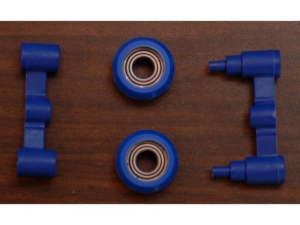
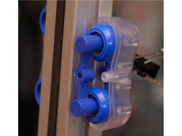
The carriage rollers are made from two bearing sleeves and a single R4ZZ bearing. You'll need to install two sleeves on each of the 12 bearings included in the kit.
-
Start by laying a sleeve half on the table, face up. Set an R4ZZ bearing into it and firmly press it into place.
-
Set another sleeve half on the table and press the R4ZZ bearing and sleeve into the new sleeve half to complete the carriage wheel.
-
Note that the sleeves have a sharp edge to them where they were cut free from the bulk stock during manufacture. Take special care not to injure yourself on this edge. It can easily be removed with a razor knife if you so choose.
-
-
-
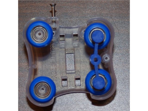
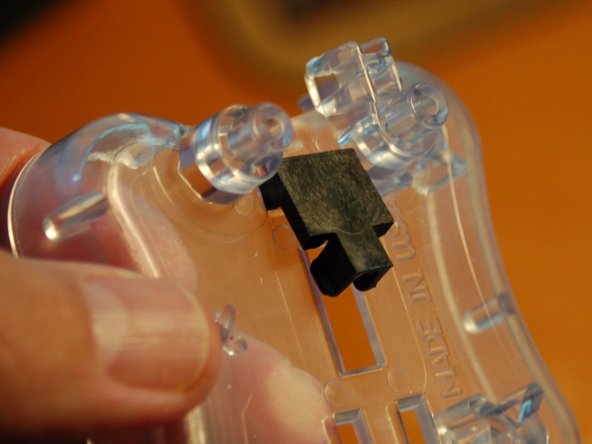
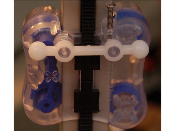
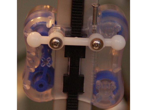
Install one #4-40, 3/8" flat head screw into the top of each inner carriage half. Make sure you drive the screw to the depth indicated in the photograph.
-
-
-
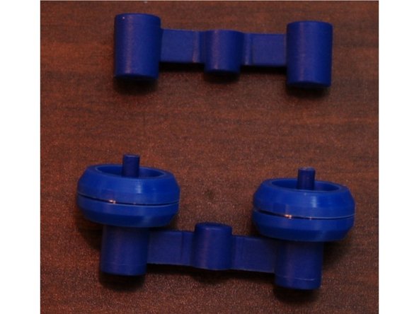
The spring arms consist of an inner and outer halves that retain two of the R4ZZ bearing rollers you assembled in Step #1.
-
Set two RZ44 bearings on the inner spring arm as shown in photo #2.
-
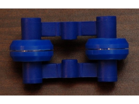
Press fit the outer spring arm on to the two small posts protruding from the inner spring arm. The fit is very tight, but they will fit!
-
In order to fully seat the pins once they're started in the holes, you can tap them in using the back end of your screwdriver as a hammer.
-
Assemble three complete sets.
-
-
-
Your first task will be to remove the old Cheapskate carriage from the tower you'll be installing this new carriage on. I recommend working with one tower at a time. There's no need to remove all three carriages at once.
-
Install two RZ44 rollers and a spring arm on to an inner carriage half. Make sure you match the spring arm orientation as shown - installing it backwards can damage the spring arms!
-
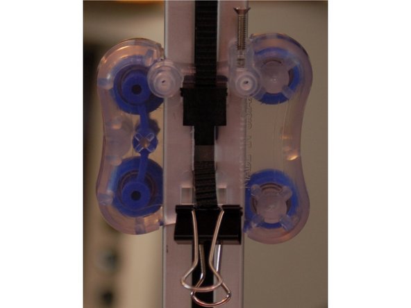
Route the two belt ends through the face of the inner carriage and attach a binder clip to the ends. This will prevent them from slipping out of the carriage while you're working on it.
-
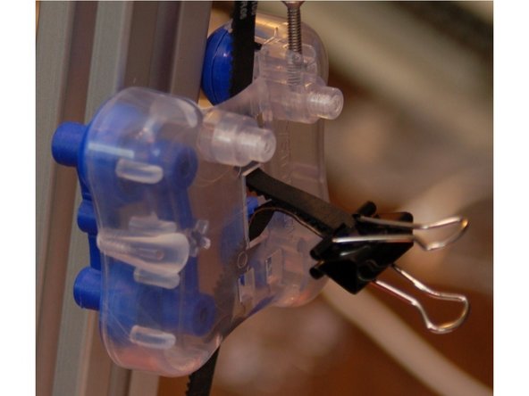
Clip the carriage on to the tower by setting the left pair of rollers into the tower groove and then the right. The spring arm should provide plenty of tension to hold the carriage in place.
-
-
-
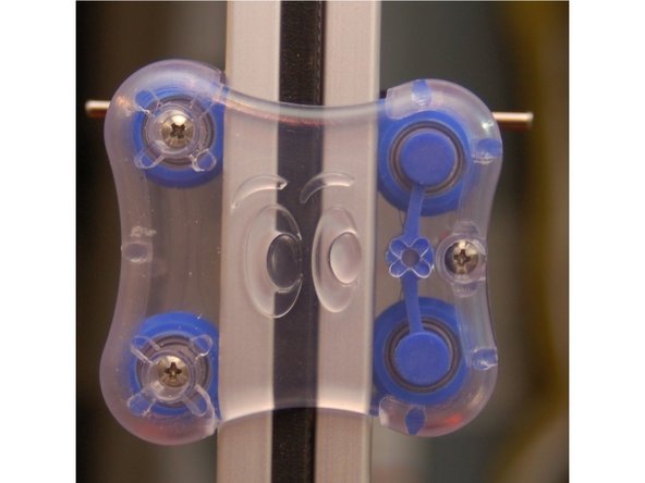
Set the outer carriage half against the inner carriage half and fix in place using three #4, 1/2" machine screws.
-
The halves will be pulled together snugly once the screws are tightened down.
-
-
-
Start by attaching a clip to the "top" belt end. The clips have two "legs" that fit into square holes above the belt opening. Fit the belt clip over the belt with the legs hooked into those holes. Rotate the belt clip "in" and the tabs on the clip sides will engage the sides of belt opening.
-
Pull the bottom belt tight and install the second clip. If you're careful, you won't need to adjust the belt tension when you're done.
-
This completes the installation of the carriage! If you're upgrading a Rostock MAX with the U-Joint based arms, go to the next step. If you're upgrading to the new carriages AND the ball-cup based arms, advance to the step titled "Installing the Ball Arms"
-
-
-
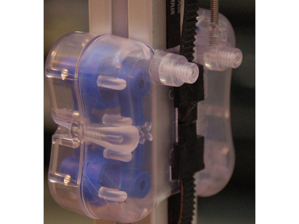
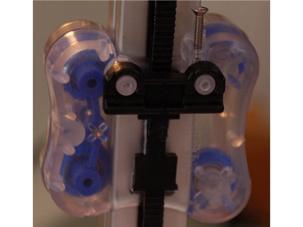
Install an axle support on to the two posts on the face of the carriage as shown in the first photograph.
-
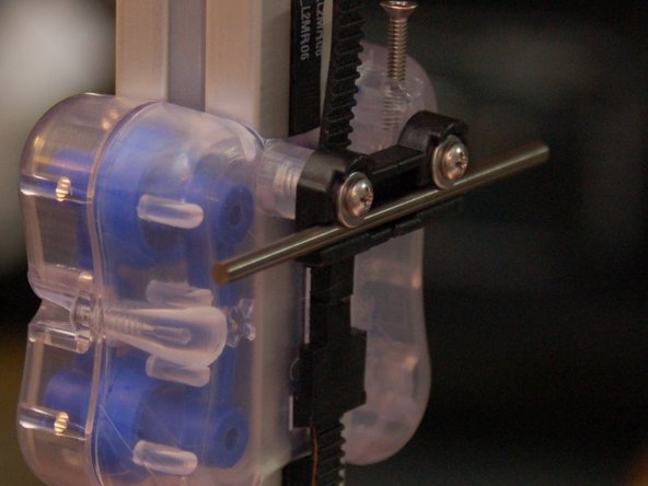
Fit a 3" axle into the axle groove in the mount. Ensure that it's centered on the carriage.
-
Using two #4, 1/2" machine screws and two #4 washers, fix the axle and axle mount in place as shown in the second photo.
-
You're done! Re-install the delta arms - they go back on just as they did the old carriages. You'll need to change your Horizontal Radius in order to recalibrate your printer properly.
-
-
-
Press a Ball Arm on to the two mounting posts on the front of the carriage as shown in the first photograph.
-
Fix the Ball Arm in place using two #4, 1/2" machine screws and two #4 flat washers.
-
You're done! Now move on to the next HowTo, "Installing the Ball-Joint Delta Arms"!
-