-
-
First you will need the following items:
-
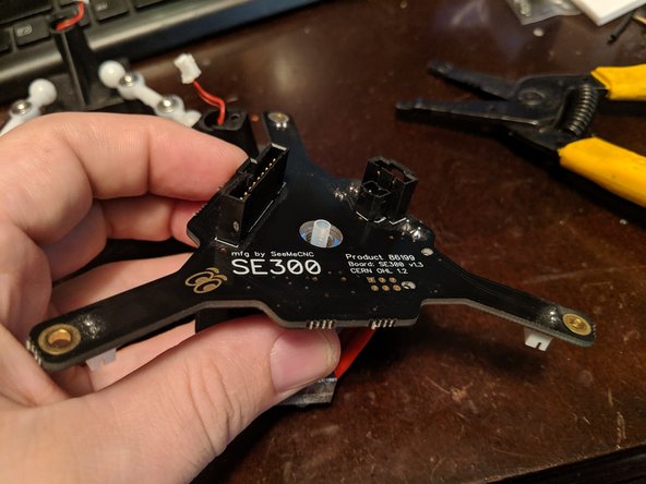
SE300 Retro fit kit as shown in Pic 1
-
Soldering iron. Preferably one with adjustable temperature.
-
Desoldering braid.
-
Solder. I use .032 diameter rosin core solder.
-
-
-
First thing you will do is remove the PTFE tube from the hotend.
-
Remove the lanyard clip holding the PTC adapter collar in place.
-
Push the black collar on the PTC adapter and slide the PTFE tube out of the PTC adapter on the hotend.
-
Cut the zip tie holding the wires to the circuit board and remove.
-
-
-
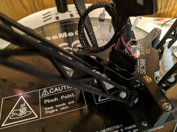
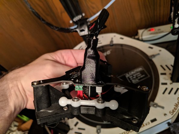
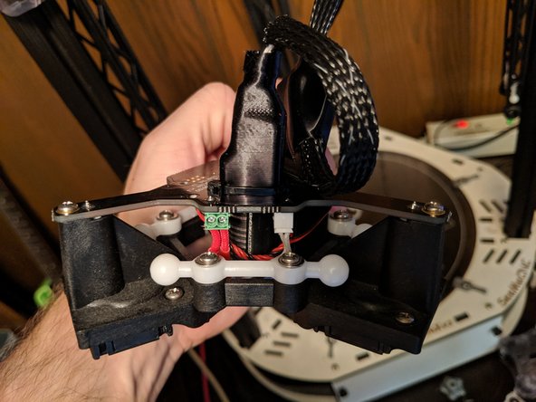
Lift the boot covering the 10 pin connector and unplug the 10 pin connector from the hotend as shown in Pic 1.
-
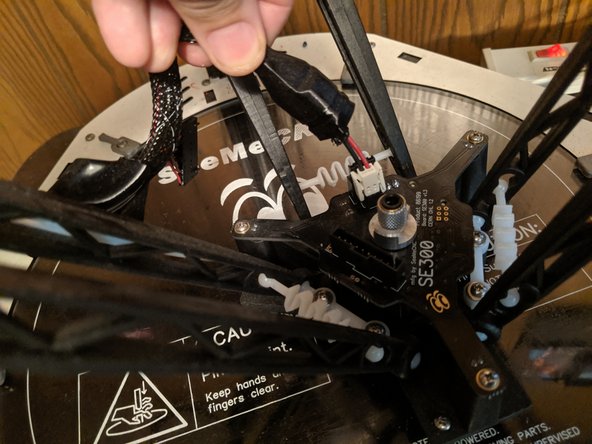
Lift the boot from the other plugs as shown in Pic 2 and unplug the clips under this boot as well.
-
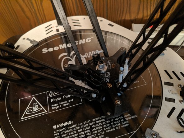
The hotend is now completely unplugged as shown in Pic 3.
-
The ball cup arms just pull off the ball joints. Remove all 6 arms from the hotend and remove the hotend from the machine.
-
-
-
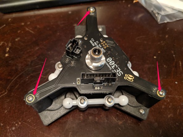
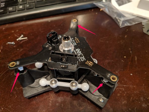
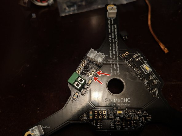
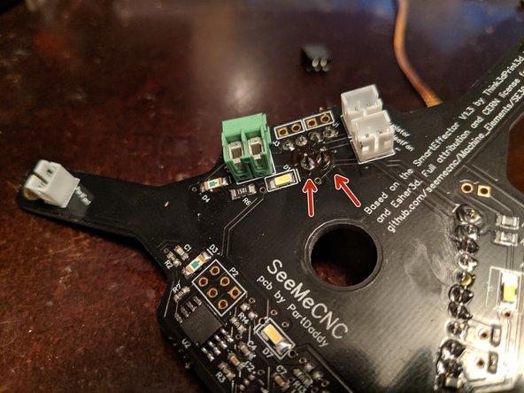
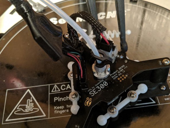
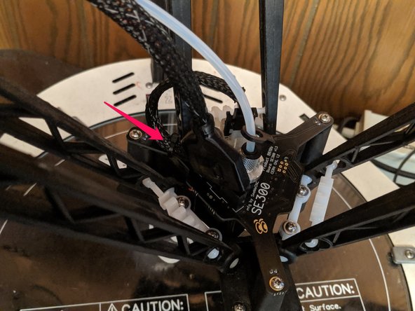
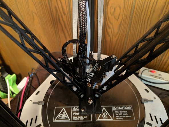
Remove the 3 screws holding the SE300 board to the platform. These are shown in Pic 1 with red arrows.
-
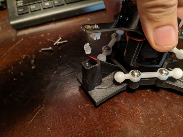
Slightly lift the hotend and this will expose the 3 layer fan plugs as shown in Pic 2.
-
Unplug the fans from the SE300 boards as shown in Pic 3.
-
You can now lift the hotend and circuit board away from the platform and set the platform to the side.
-
-
-
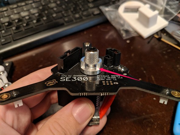
Loosen the locking collar the red arrow is pointing to on the PTC as shown in Pic 1.
-
With the collar loosened as shown in Pic 2, you can unscrew and remove the PTC adapter and set it aside.
-
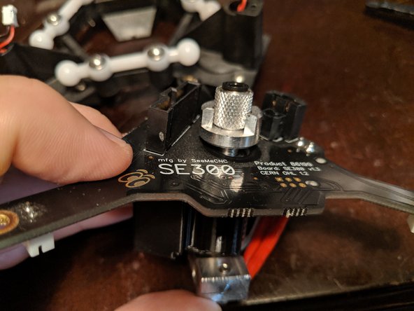
The hotend should now look like Pic 3.
-
-
-
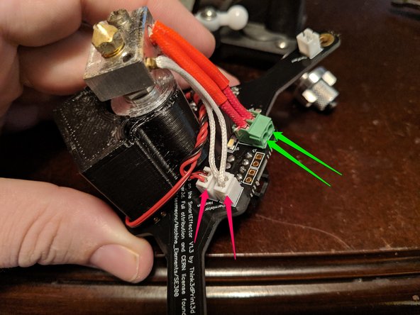
Unplug the thermistor (plug with 2 white wires) and the heat sink fan (white plug with red and black wires. As shown with the RED arrows in Pic 1.
-
Unscrew the heater cartridge terminals as shown in Pic 1 with the GREEN arrows. You should now be able to lift away the hotend and set it aside.
-
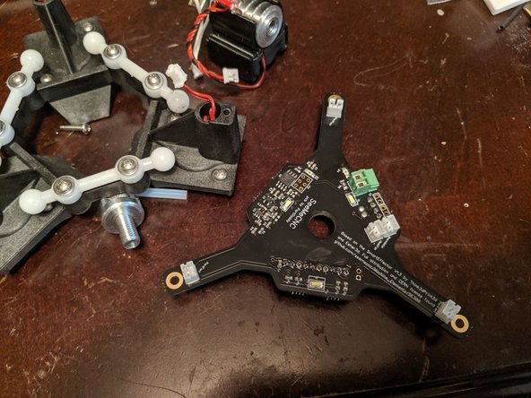
The SE300 board should now be by itself for you to work on it as shown in Pic 2.
-
-
-
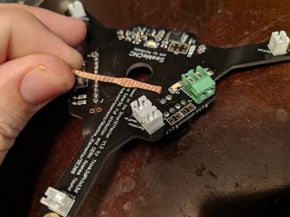
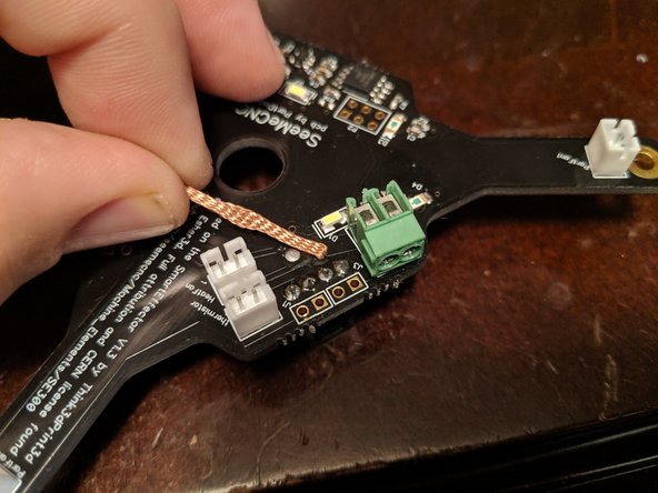
I set my soldering iron to 476c (about 880 F) on my soldering iron for this task. Heat your soldering iron and get your desoldering braid ready as shown in pic 1.
-
Place the desoldering braid over the first heater connector solder point as shown in Pic 2.
-
Place the soldering iron on the desoldering braid and allow it to heat up both the desoldiering braid and solder point and the desoldering braid will wick up the solder.
-
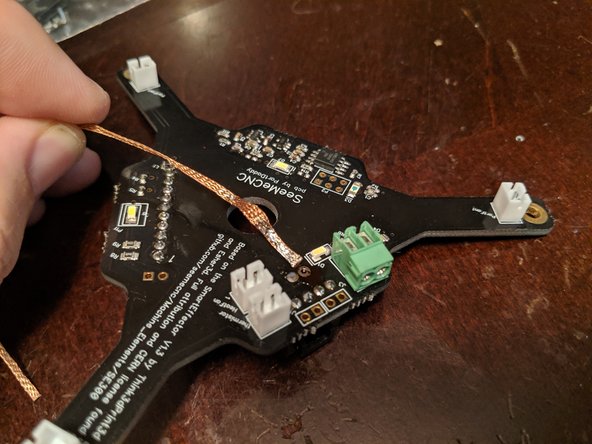
It will take multiple points on the desoldering braid to desolder all the solder that is in the hole.
-
You can see in Pic 3 the desoldering braid with the soaked up solder and the clean hole for the heater solder point.
-
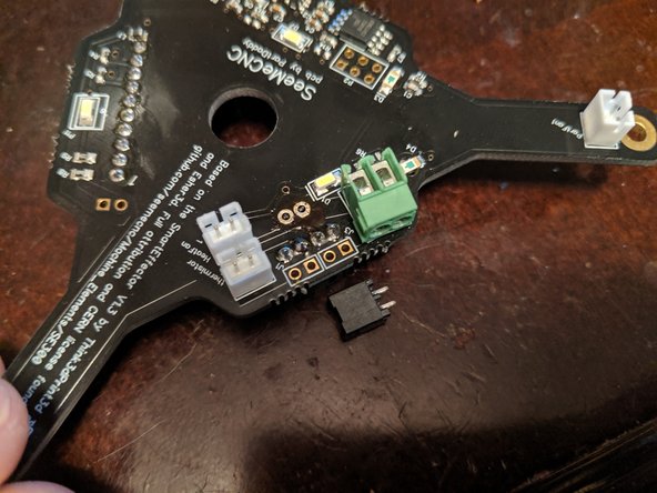
Repeat this process for the second solder point on the heater plug. Once both are clean of solder, you may still need to heat the points while pulling on the power plug for any residual solder inside the hole and remove the power plug.
-
-
-
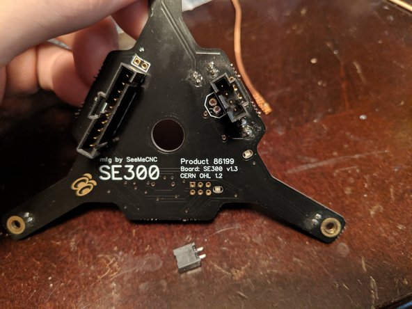
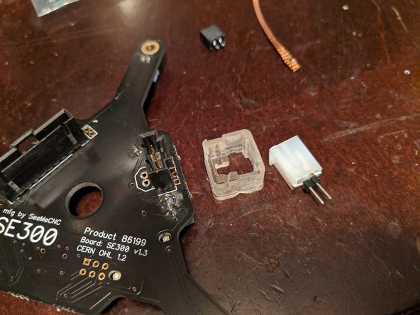
In Pic 1 you can see the removed power plug and the cleaned solder points from the PCB.
-
Pic 2 shows the top of the SE300 board with the plug removed and the cleaned solder points.
-
-
-
Get the support ring and the new power plug from the Retro Fit Kit (your ring may appear different or different color).
-
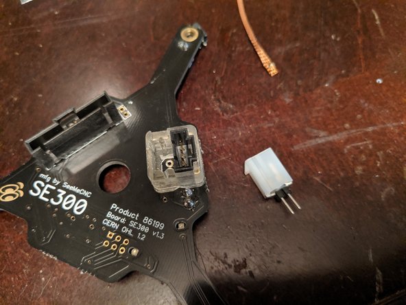
Place the ring over the 4 pin connector remaining on the hotend board as shown in Pic 2. This will be a tight fit but should slide over the 4 pin.
-
Insert the new power plug into the other side of the retaining ring of the Retro Fit Kit, and insert the legs of the plug through the now-cleaned soldering holes on the board.
-
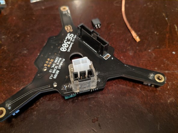
Take note which side the clip is on for the plug you are adding. Polarity is IMPORTANT so it must be inserted as shown in Pic 3!
-
-
-
Pic 1 shows the under side of the board with the new plug installed. You can see the legs of the new power connector sticking through the board.
-
Solder the two legs to the PCB as shown in Pic 2 to secure the power plug in place.
-
You can now re-assemble the hotend to the PCB and the PCB to the platform in the reverse order you removed them.
-
If you need to re-reference how to assemble the hotend to the PCB and the PCB to the platform, you can follow the SE300 build guide located HERE.
-
-
-
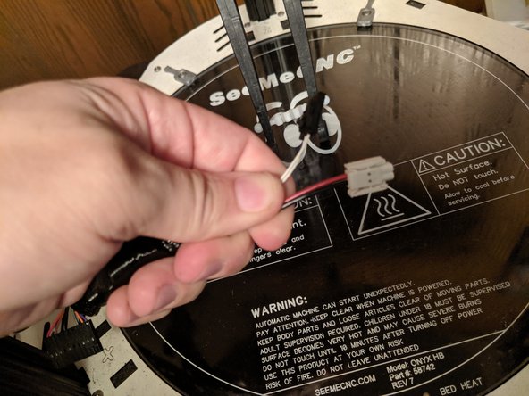
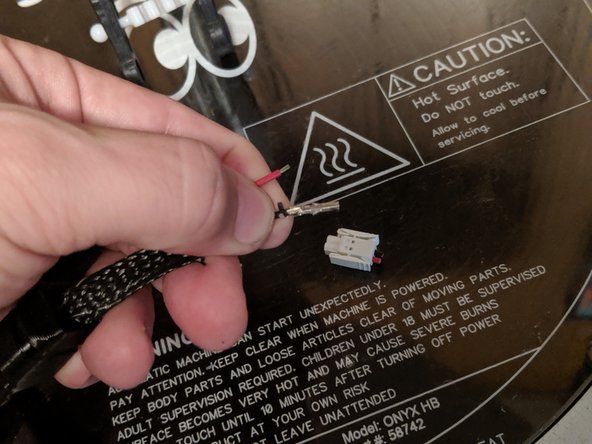
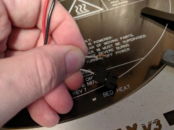
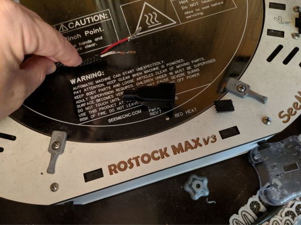
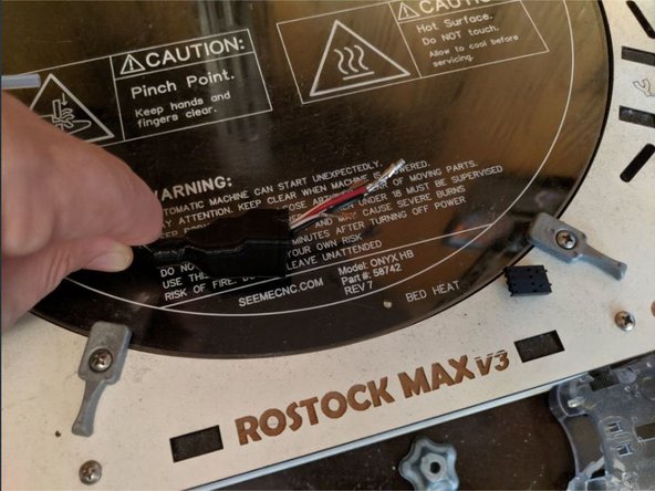
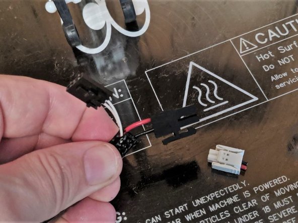
Moving back to the machine, we will now work on the whip to alter the power plug shown in Pic 1.
-
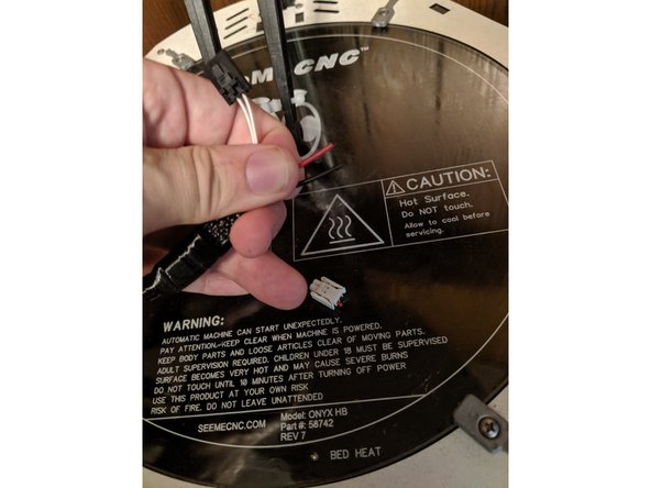
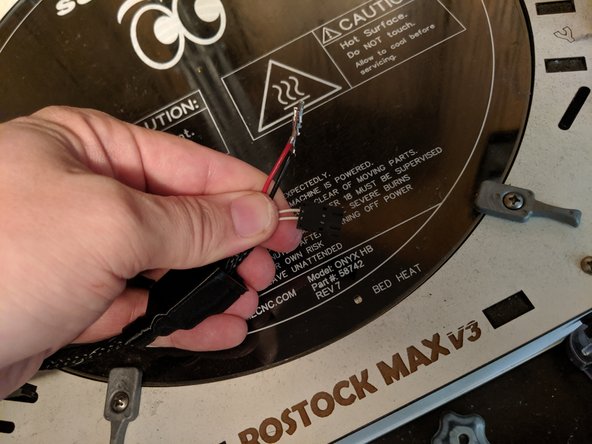
Locate the white 2 pin power plug and cut off the plug to remove it. Cut the wires as close to the white plug as possible to give you the most wire to work with as shown in Pic 2.
-
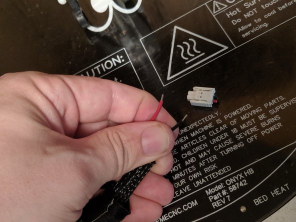
Strip off a few millimeters of the covering of the wire as shown in Pic 3.
-
-
-
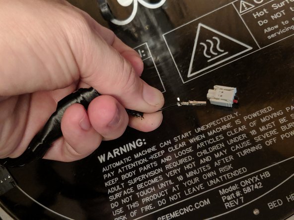
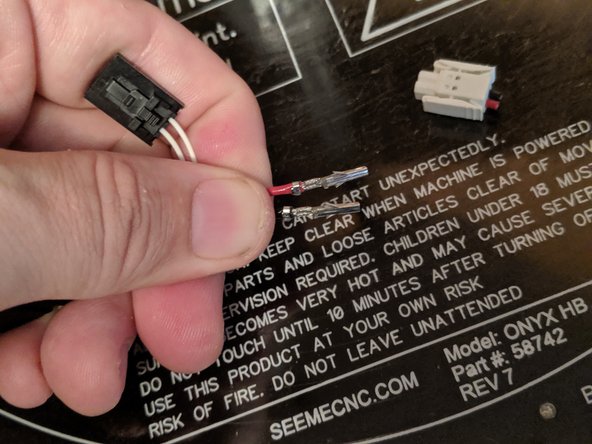
Take the terminal ends and line them up as shown in Pic 1. You will have the bare wire in the channel of the inside tabs, and the wire coating in the channel of the outside longer tabs.
-
Crimp the inner tabs to secure the crimp to the bare wire. On my crimping pliers I use the 1.9mm crimp location. The crimped wire can be seen in Pic 2.
-
Repeat this for the inner tabs on the other wire as shown in Pic 3.
-
-
-
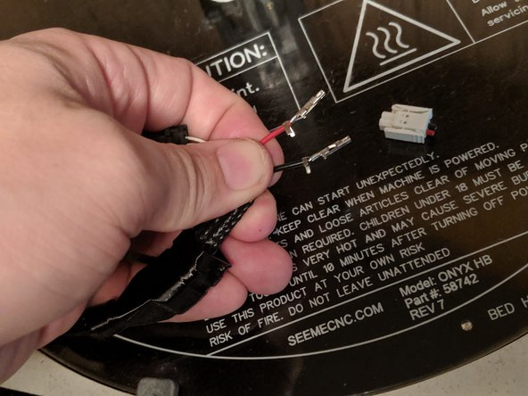
Complete the crimp by crimping the larger tabs. If your crimper only does small wires like mine, you can use needle nose pliers to wrap the tabs around the wires. Make sure they are tight enough to hold on to the wire as shown in Pic 1.
-
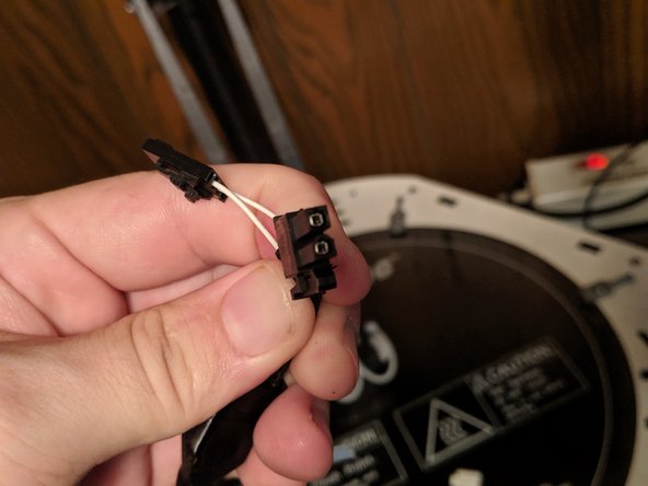
Now that the connectors are installed, we will remove the white thermistor wires from the plug. You will see in Pic 2 there are windows in the plug where you can see the connector on the inside.
-
You will want to insert something pointy in this window while sliding the wire out of the housing. Inserting something in the window will compress the clip that holds the clip in the housing
-
You should be able to slide the connector out as shown in Pic 3.
-
Repeat this for the other wires so both are removed. Set the plug to the side as you will still use it.
-
-
-
You can see in Pic 1 the small tab that has now been compressed. Using a fingernail, GENTLY lift the tab so it can click back into place when re-inserted.
-
Pic 2 shows the lifted tab so you can see it is just a small raise.
-
-
-
You will now have all the connectors and the square rubber boot as shown in Pic 1.
-
Slide the boot over all the wires and the loom as shown in Pic 2. Slide it up enough so you have room to work on the plug wires.
-
-
-
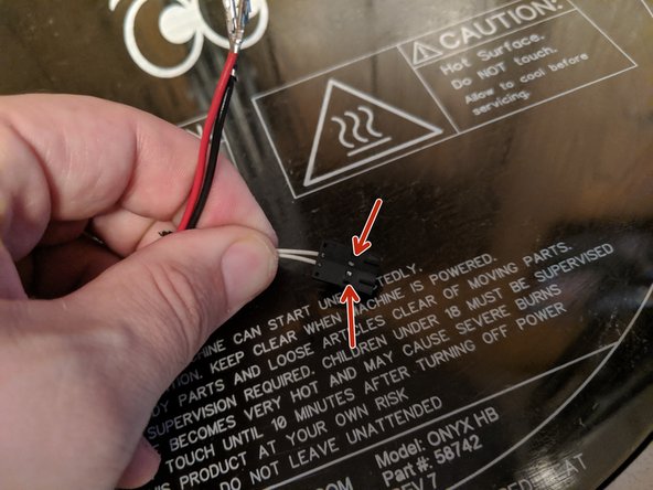
Insert the white wires into the connector in the 2 middle pins as they were located before removal. Polarity does not matter
-
You will insert the plugs into the black clip with the tabs you lifted facing towards the side with the window. You will insert them until you hear an audible click and they should lock into place.
-
The plug should look like Pic 1.
-
-
-
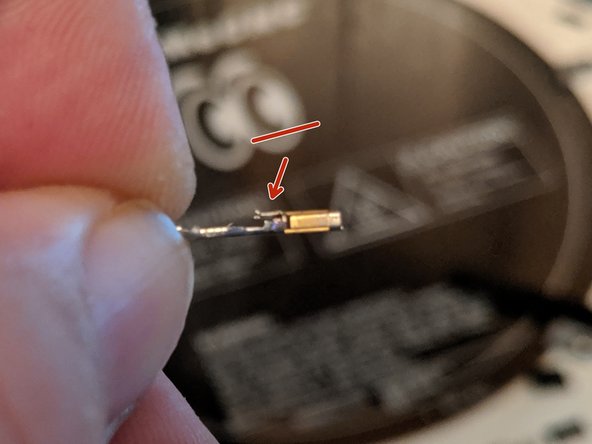
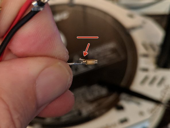
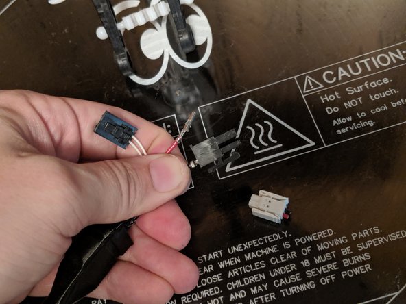
You can now insert the terminals into the new black power plug. They will only insert into the black housing one way, so if it feels like it is not going in fairly smoothly, rotate the wire. The clips that stick out of the sides of the metal clip will face the side you see in Pic 1.
-
Note that the black wire goes into the position next to the tab and the red wire goes on the opposite side! Polarity is important!
-
Insert the terminals fully into the plug as shown in Pic 3.
-
-
-
You can see the wires are fully inserted when you can see the terminals in the end of the plug as shown in Pic 1.
-
Plug the hotend back to the whip as shown in Pic 2.
-
-
-
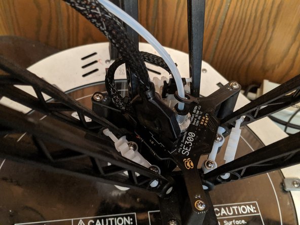
Slide the boot over the plugs as shown in Pic 1.
-
Place a zip tie over the boot to secure it in place as shown in Pic 2.
-
Place a zip tie on the wiring to secure the whip to the circuit board as shown by the arrow in Pic 3.
-
-
-
You can now re-connect the PTFE tube and arms in the reverse way you installed them at the beginning of the guide to finish the build.
-
Congratulations! Your retro-fit of the power plug is now complete!
-