-
-
Disconnect the power cable from the machine.
-
Disconnect the USB drive from the machine.
-
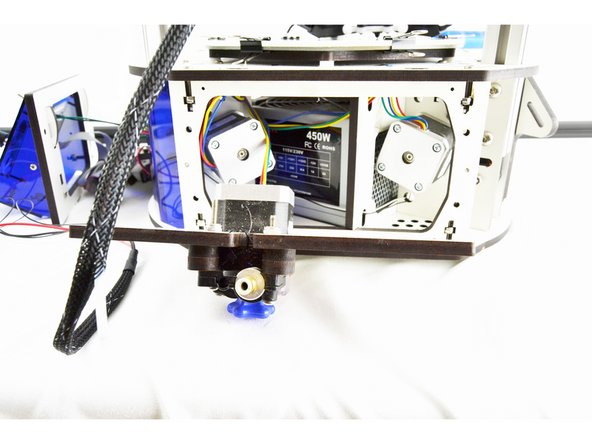
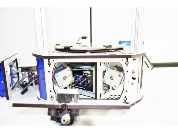
Set your Orion Delta on a clean work space with plenty of room.
-
-
-
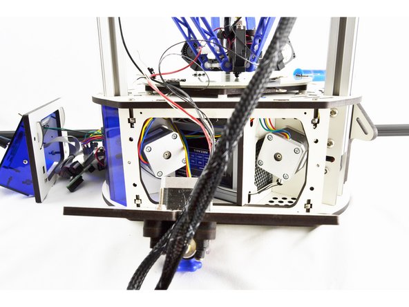
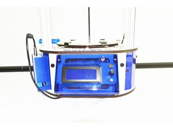
Remove the LCD controller (Front Bezel) from the front of the printer. There are (2) thumb screws attaching it to the printers base.
-
-
-
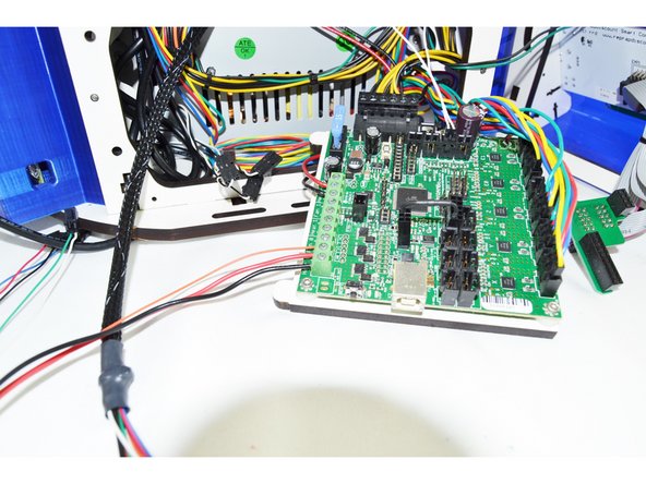
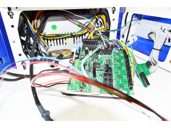
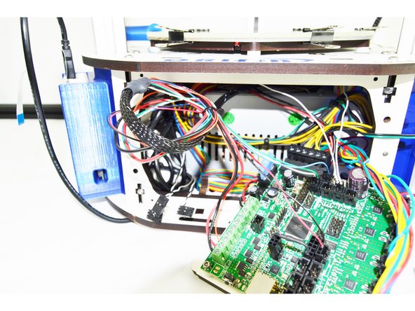
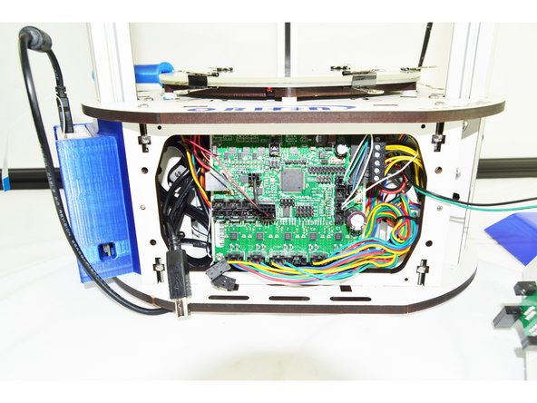
To remove the RAMBo board from the machine, you will need to:
-
Remove the end-stop plugs from the RAMBo board. You will want to remove them one at a time and label them (on the black 3 pin housing) with a sharpie marker. In order from left to right, these are X Y Z. Be sure to remove them one at a time and label them!
-
You may also need to remove the Stepper Motor 4 pin connectors from the RAMBo board. Just as above, you will need to remove them one at a time and label them upon removing them. They are (from left to right) X Y Z _ E0 _ Be sure to remove them one at a time and label them!
-
You will have enough excess wire length for the remaining wires to get the RAMBo board out of the base.
-
The RAMBo board is mounted to a backer board. You will grasp that backer board on the bottom left and right pull out. The bottom of the RAMBo (and backer) should pull freely and tip out. Once the top ears on the backer board have cleared the top plate of the base, the entire board can be removed.
-
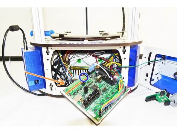
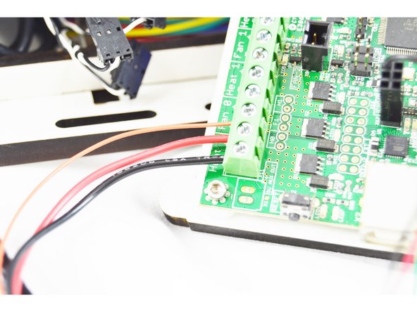
With the RAMBo partially removed and accessible. You will not remove the output wires. You will use a scewdriver to loosen the following terminals: Heat 0, Heat 1, and Fan 0. These are noted in the pic with the orange arrow. DO NOT REMOVE THE WIRES LOCATED AT HEAT 2 (NOTED WITH A BLUE CIRCLE)
-
-
-
To remove the hotend whip you will first need to remove the side panel with the extruder. This panel is secured with (2) thumb screws.
-
Once the thumb screws have been removed, lay the panel down on its side.
-
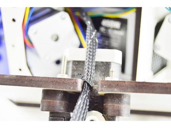
Cut the cable tie securing the existing wiring whip to the side panel.
-
-
-
Pull the wires from the existing hotend whip through the base assembly, out the side with the extruder panel (removed)
-
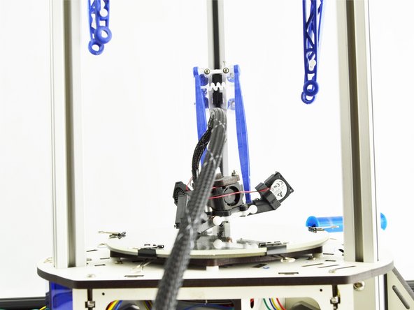
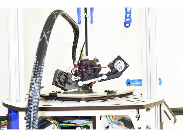
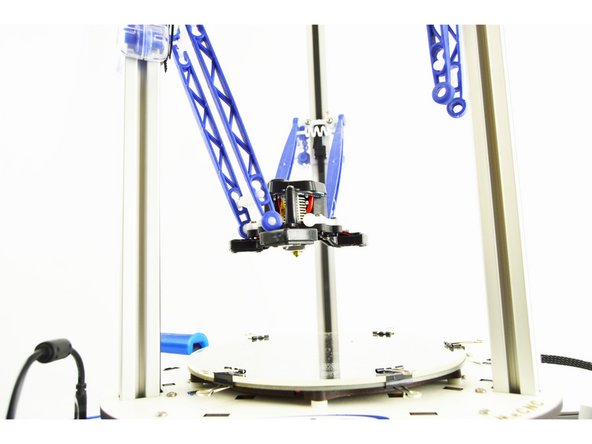
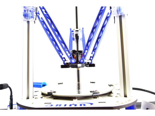
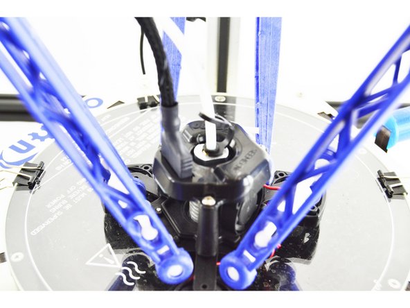
Remove the ball cup arms from the effector platform. To do so, gently pull the ball cup arm off of each ball joint.
-
Perform this operation with all (6) arms.
-
Be sure not to loose the tension springs that go between each set of arms.
-
-
-
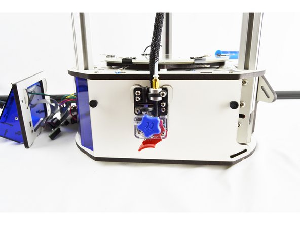
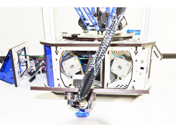
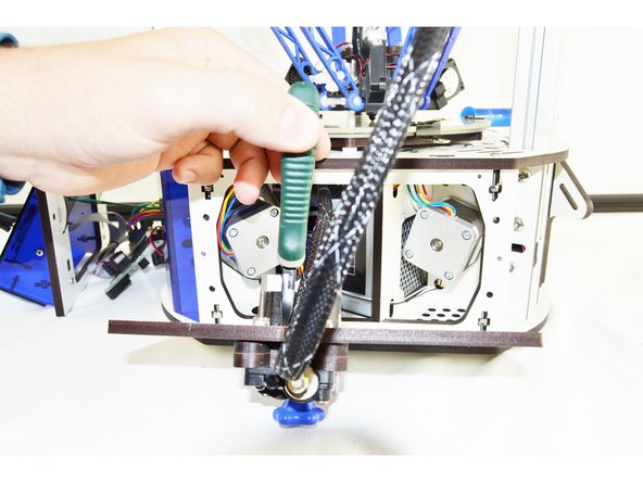
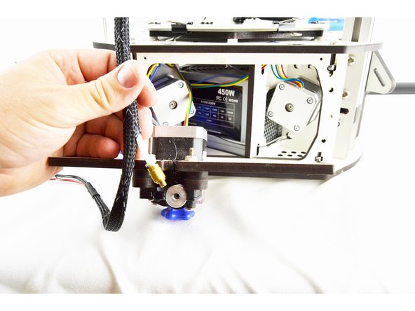
Remove the bowden tube from the extruder.
-
You may find it easiest to remove the PTC fitting from the extruder first and then remove the bowden tube from the fitting as shown in the pictures. If you choose to do it this way, be sure to replace the PTC fitting so it does not get lost.
-
With the bowden tube all 6 arms removed, the effector and whip are now be completely removable from the printer. Remove it and set it aside.
-
-
-
From the front of the printer, insert the new whip (8 pin connector first) through the front of the machine, over the hot end and out the side of the machine with the extruder panel removed.
-
-
-
Insert wisdom here.
-
-
-
Insert wisdom here.
-
-
-
Insert wisdom here.
-
-
-
Insert wisdom here.
-
-
-
Insert wisdom here.
-
-
-
Insert wisdom here.
-
-
-
Insert wisdom here.
-
-
-
Insert wisdom here.
-
-
-
Insert wisdom here.
-
-
-
Insert wisdom here.
-
-
-
Insert wisdom here.
-


