Difficulty
Moderate
Steps
7
Time Required

In Progress
This guide is currently being written. Reload periodically to see the latest changes.

User-Contributed Guide
This guide is not managed by the site's staff.

Private
This guide will not appear in search results and can only be viewed by team members!
Quiz
0
-
-
The photos in this step show you the hardware you'll need before you can begin work.
-
Image #1 shows the three #6-32 thumbscrews, 1" threaded standoffs and the three #6-32 x 3/8" screws used to attach the standoffs to the effector platform.
-
Image #2 shows the required male & female JST connectors that will be used to wire up the PEEK and layer fans.
-
Image #3 shows the 4 pin latching connectors that are used to wire up the hot end power and thermistor connections.
-
-
-
Cut the Layer fan wires where you soldered them together during the build. Mark the ends coming from the wiring loom as "Layer" so you can identify them later.
-
Cut the PEEK fan wires where you soldered them together during the build. Mark the ends coming from the wiring loom as "PEEK" so you can identify them later.
-
Measure 1-1/4" from the top of the melamine hot end mount and cut the four wires leading to the hot end.
-
Using your Phillips screwdriver & 5/16" wrench, remove the three screws that hold the hot end to the effector platform.
-
We're now ready to start adding connectors!
-
-
-
If you've never used a crimping tool before, I recommend taking a look at this tutorial from Hansen Hobbies: http://www.hansenhobbies.com/products/co...
-
Grab a pair of male JST connector pins and crimp them on to the Layer fan leads.
-
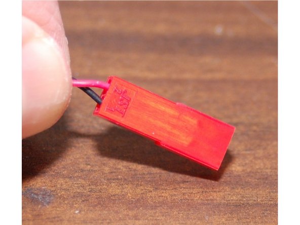
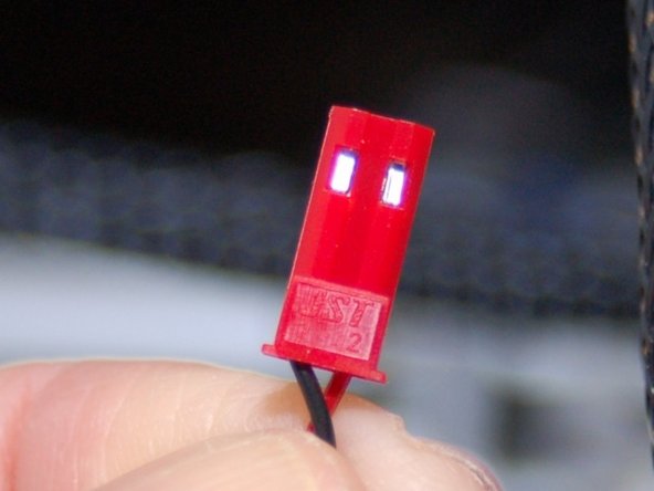
Insert the black wire into the #1 position and the red wire into the #2 position as shown in image #2.
-
-
-
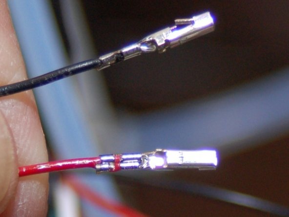
Grab your female JST connector and crimp the 2 pins for that on to the Layer fan power wires coming out of the mesh loom on the Rostock MAX.
-
Insert the sockets into the JST housing as shown in the 2nd image. Remember, the black wire goes into position #1 and the red wire goes into position #2. They're numbered, but can be hard to see.
-
-
-
Now we're going to put the male, 4 pin latching connector on to the hot end.
-
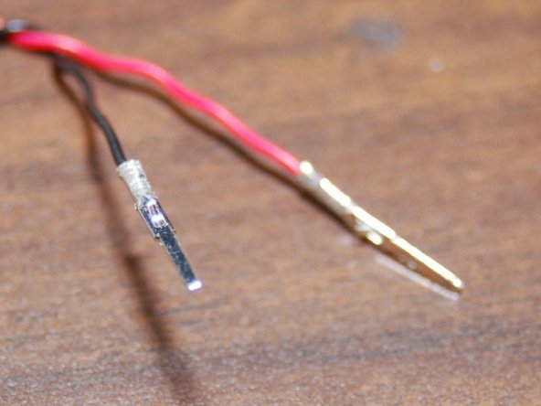
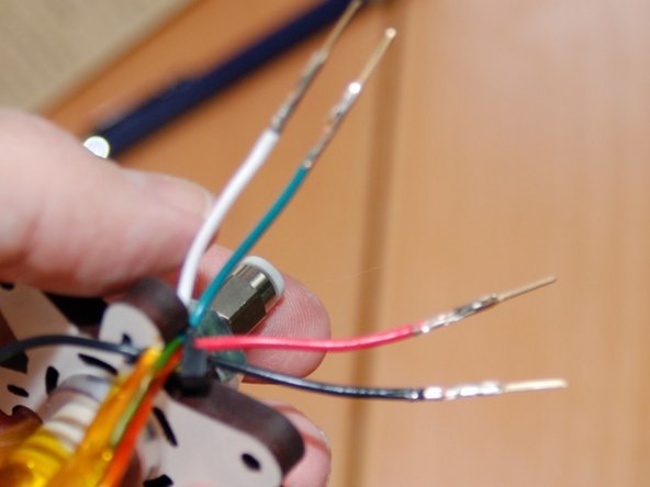
Strip about 1/4" of insulation from the four wires coming off the hot end. Depending on the version of the Rostock MAX you have, you'll either have 2 18ga and 2 26ga wires, or 4 18ga wires as shown in photo #1. Add a male crimp pin to each of the four wires.
-
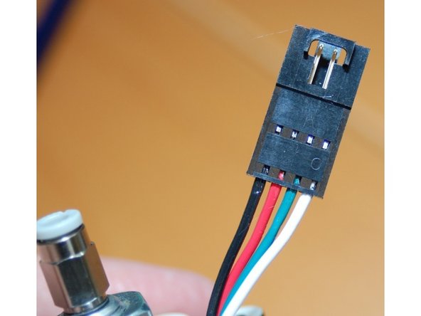
Insert the wires into the male connector shell as shown in photo #2. Make sure you've got the orientation correct! You do NOT want to put power to the thermistor! You'll destroy it. If your hot end uses 2 18ga and 2 26ga wires, ensure that the 18ga wires go into the first two positions on the left of the connector (red & black).
-
This of course means that the 2 26ga wires will end up in the two positions on the right.
-
-
-
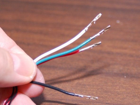
Strip about 1/4" of insulation off of the two power and two thermistor wires coming out of the mesh loom on the Rostock MAX. Install a female crimp socket on each.
-
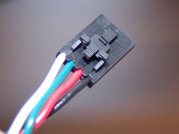
You may have two 18ga and two 26ga wires or four 18 ga wires for your hot end. Just as in the previous step, make sure you've got the black & white wires inserted in the positions shown in image #2.
-
-
-
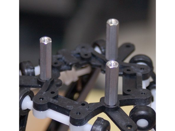
Using the #6-32 3/8" pan head screws you got, install the 1" F-F hex spacers on to the effector platform as shown.
-