-
-
The photos in this step show you the hardware you'll need before you can begin work.
-
Image #1 shows the three #6-32 thumbscrews, 1" threaded standoffs and the three #6-32 x 3/8" screws used to attach the standoffs to the effector platform.
-
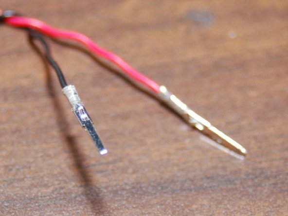
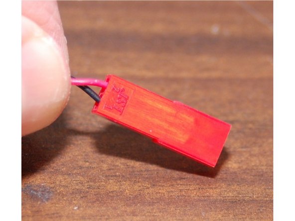
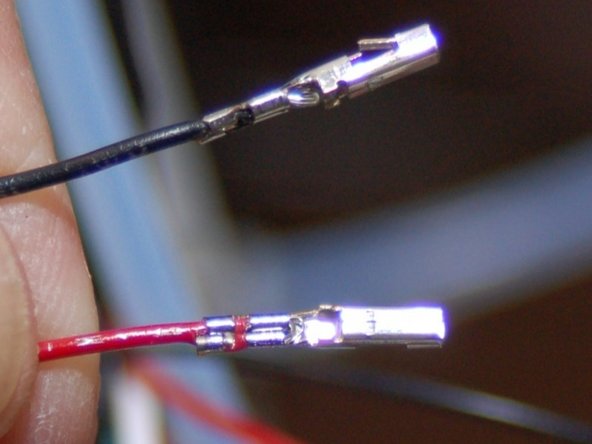
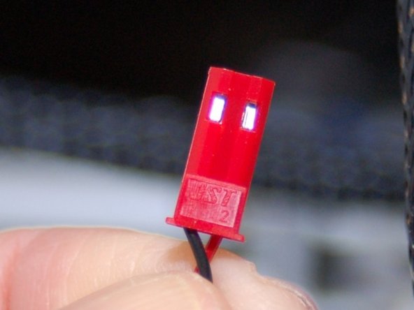
Image #2 shows the required male & female JST connectors that will be used to wire up the PEEK and layer fans.
-
Image #3 shows the 4 pin latching connectors that are used to wire up the hot end power and thermistor connections.
-
-
-
Cut the Layer fan wires where you soldered them together during the build. Mark the ends coming from the wiring loom as "Layer" so you can identify them later.
-
Cut the PEEK fan wires where you soldered them together during the build. Mark the ends coming from the wiring loom as "PEEK" so you can identify them later.
-
Measure 1-1/4" from the top of the melamine hot end mount and cut the four wires leading to the hot end.
-
Using your Phillips screwdriver & 5/16" wrench, remove the three screws that hold the hot end to the effector platform.
-
We're now ready to start adding connectors!
-
-
-
If you've never used a crimping tool before, I recommend taking a look at this tutorial from Hansen Hobbies: http://www.hansenhobbies.com/products/co...
-
Grab a pair of male JST connector pins and crimp them on to the Layer fan leads.
-
Insert the black wire into the #1 position and the red wire into the #2 position as shown in image #2.
-
-
-
Insert wisdom here.
-


