Difficulty
Easy
Steps
5
Time Required

User-Contributed Guide
This guide is not managed by the site's staff.
Quiz
0
Tools
-
-
The new platform design requires that you print both a new PEEK and Layer fan shroud. Print both of these now, BEFORE you tear your printer apart. :)
-
The PEEK fan shroud can be found here: PEEK FAN SHROUD
-
The Layer fan shroud can be found here: LAYER FAN SHROUD
-
-
-
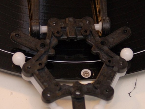
Press a Ball Joint Arm on to two of the mounting posts on the under side of the Ball Joint Platform.
-
Fix in place using two #4, 3/8" sheet metal and two #4 flat washers.
-
Repeat for the other two mounting locations as shown in the third image.
-
-
-
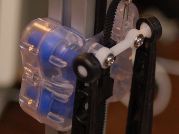
Attach a Ball Joint Arm to the ball joints on the carriage as shown. As you press the socket over the ball on the carriage, you'll hear a faint "click" as it locks into place.
-
Attach the Ball Joint Platform you assembled previously to the other ends of the arms as shown.
-
-
-
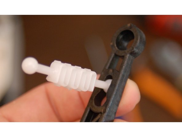
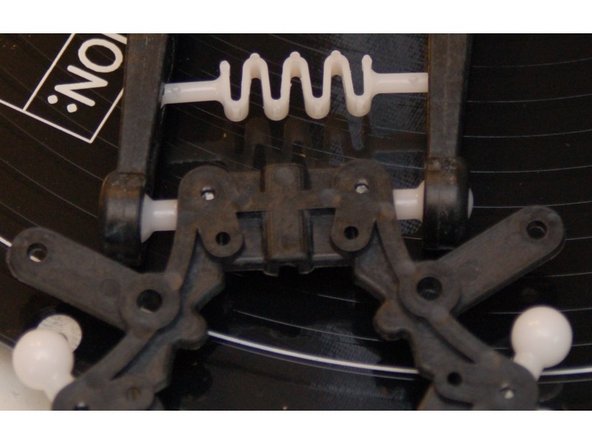
Insert the end of the tension spring into the keyhole notch in the arm as shown.
-
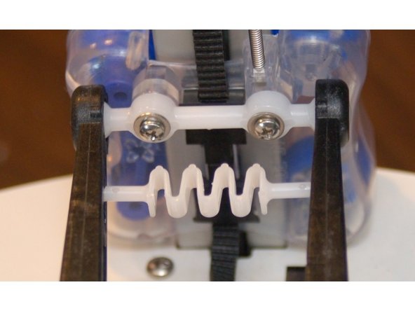
Gently stretch the spring across to the opposite arm and latch it into the keyhole notch.
-
Perform this step at both tension spring locations - the "top" end at the carriage and the "bottom" end at the Ball Joint Platform.
-
Repeat this and the previous step for the other two pairs of arms.
-
-
-
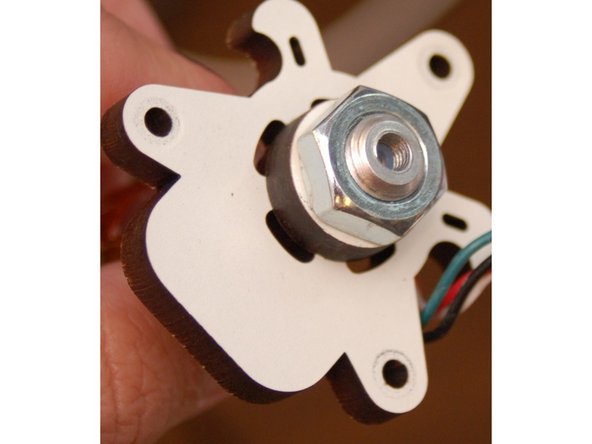
Remove the hot end from the old-style platform and install it into the new style.
-
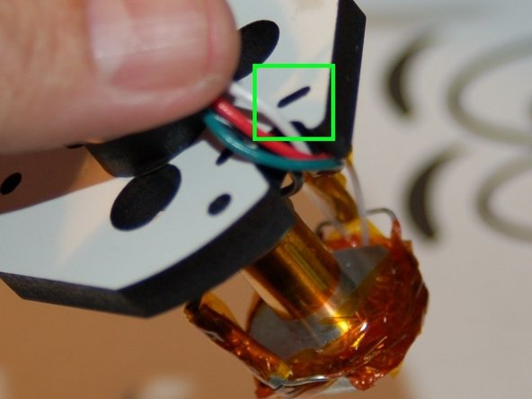
Tie the wires to the strain relief using a 4" wire tie in the notch shown.
-
Install the hot end on to the new platform.
-
This new arm upgrade has significantly changed the geometry of the printer. Because of this, you'll need to recalibrate. In order to do this successfully, you'll need to change your Horizontal Radius to 140 (if you haven't already) and the Diagonal Rod length to 290.8.
-
If you're upgrading an Orion, you'll want to set the Horizontal Radius to 89 as a starting point. The Diagonal Rod length is 179.0
-
You're done!
-