
Difficulty
Easy
Steps
5
Time Required

User-Contributed Guide
This guide is not managed by the site's staff.
Quiz
0
-
-
Obtain the required components outlined in the"Tools" & "Relevant Parts" of this How-To
-
Remove the side panel (between the X & Z Tower) from your Rostock Max v2
-
Download and print the required drill template. (You will need to ensure in the print settings that there is no scaling being applied.) Diagram Link
-
Install AstroPrint or OctoPrint on the Raspberry Pi. Here is a tutorial on installing and setting up AstroPrint.
-
-
-
From the template that you printed, cut the drawing of the side panel out.
-
Poke holes in the two location where the thumb screws go.
-
Lay the template on the side panel and insert the thumb screws to keep the template aligned.
-
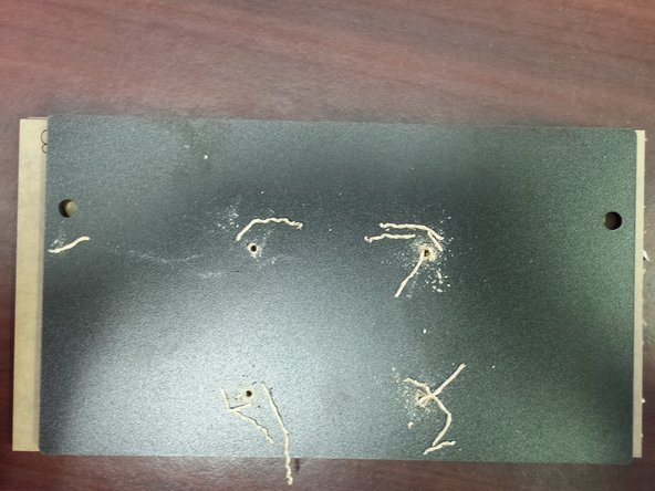
Marking Method #1 - If your machine is white you can use a sharpie marker to mark the points. Press the marker in the center of the center marks for the 4 screw locations. This will allow the marker the bleed through and mark the locations.
-
Marking Method #2 - If your machine is black you may find it easier to use a pin, or other sharp point to mark the locations of the centers of the holes.
-
-
-
Using a #42 drill bit you should now drill holes in the 4 locations previously marked. Be sure to use a put a scrap piece under the side panel does not split out (and you don't drill through your table!)
-
-
-
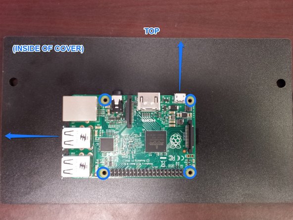
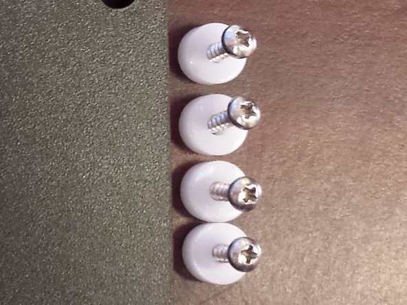
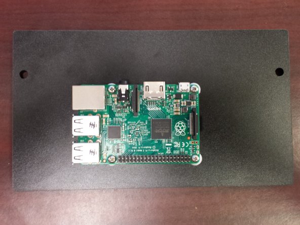
Using the (4) provided standoffs and (4) #4 screws, attach the Raspberry Pi to the side panel. The Micro USB connector should be facing up and the USB and ethernet connectors should be facing to the left of the side panel. Be sure not to over-tighten the screws!
-
-
-
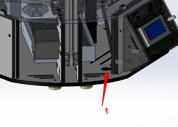
Route the Micro USB the opening in the base of the machine noted with the RED #1 in the first image.
-
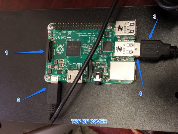
Connect the following to the Raspberry Pi (noted in the second image with BLUE ARROWS AND TEXT)
-
#1 Micro SD card
-
#2 Micro USB power cable
-
#3 USB Cable (I chose to zip tie my USB cable so that all the slack was not spread around loosely inside the base of the printer)
-
#4 WiFi USB wireless adapter
-
Carefully install the side panel on the Rostock Max v2
-


Cancel: I did not complete this guide.
2 other people completed this guide.
Attached Documents
