Difficulty
Moderate
Steps
37
Time Required
- Droplit v2 Carriage Assembly 7 steps
- Droplit v2 Injection Molded Vat Assembly 4 steps
- Droplit v2 Mirror Mount Sub Assembly 4 steps
- Droplit v2 Frame Assembly 22 steps

User-Contributed Guide
This guide is not managed by the site's staff.

In Progress
This guide is currently being written. Reload periodically to see the latest changes.

Private
This guide will not appear in search results and can only be viewed by team members!
Quiz
0
-
-
The hardware for this assembly is located in the bag labeled 78896 Droplit v2 Carriage Assembly
-
Go ahead and locate that hardware now.
-
-
-
Locate the (4) R4 Bearings and (8) Bearing Covers.
-
Start by laying a sleeve half on the table, face up. Set an R4ZZ bearing into it and firmly press it into place.
-
Now set another sleeve half on the table and press the R4ZZ bearing and sleeve into the new sleeve half to complete the carriage wheel.
-
Repeat this process for the (3) remaining bearings.
-
-
-
-
Locate the Inner and Outer Spring Arms, shown in the animation.
-
The spring arm is easy to assemble, but the small posts are a very tight fit, so be careful when assembling them. Note that each arm half has an “inside” and “outside” to it.
-
Slide two sleeved R4ZZ bearings on to the outer spring arm posts as shown.
-
Next, press the inner spring arm on to the two mating posts that are on the outer spring arm. (Ensure the curvature of the spring arms are in the same orientation)
-
This is a very tight fit. You can get each side started by aligning the holes in the inner spring arm over the posts in the outer spring arm and then tap them into place with the handle of your P2 screwdriver. You want the pins fully seated.
-
Install the remaining two bearing with sleeves onto the R4 Bearing Bushing Block. There are 3 posts for bearings. You will be installing the bearing on the top and bottom posts. The middle post will be left empty.
-
-
-
-
Locate the Carriage Mounting Plate, M10 Anti-BackLash Nut, 10-32 Knurled Thumb Screw, (3) #4 Pan Head Phillips Screws, and (3)#4 Washers.
-
NOTE: You should have tapped the 2 holes in the carriage mounting plate as part of the Preparing For the Build Steps. If you have not done that yet, please do so now.
-
The Carriage Mounting Plate is symetrical, so it does not matter which side you attach the Anti-Backlash nut to, so long as the orientation from the animation is kept in regards to the Anti-Backlash nut and the Knurled Thumb Screw
-
The #4 Pan Head screws will self tap into the Anti-Backlash nut. At this time, you should NOT fully tighten these screws.
-
You can however fully tighten the Knurled Thumb Screw.
-
-
-
-
Locate the (2) Carriage Side Plates, Spring Arm assembly put together in step 2, (2) R4 Bearings with covers, Bearing Bushing 3/4 Position, (3) 6-32 x 2" Phillips Flat Head Screws, (3) 6-32 Nylon Lock Nuts, (7) #6 Washers, and (2) Plastic Bearings, and (1) 6-32 x 1/2" Socket Head Cap Screw.
-
The Carriage Side Plates are symmetrical, therefore left/right can be interchanged.
-
Orient the components are shown in the animation. The 6-32 x 1/2" Socket Head Cap Screw should be the last item installed to ensure that is placed in the correct location (back left side). This screw be secured with a 6-32 Nylon Lock Nut (not shown in the animation).
-
NOTE: The Spring Arms can be installed in either orientation, But when it comes time to install the Carriage on the TSLOT the Spring Arm must be in such a way that the bearings are closer to the TSLOT than the pivot point.
-
You should fully tighten the (2) 6-32 x 2" screws that attach the sides to the Bearing Bushing 3/4 Position.
-
Tighten the 6-32 x 2" screw that passes through the Spring Arms with 1/2 turn increments. You want the Spring Arms to be secured, but you still want them to be able to pivot. If you find that you have over tightened this screw and the Spring Arms no longer can pivot, back the screw out slightly until they can pivot again.
-
-
-
-
Locate the (4) 6-32 x 1" Phillip Pan Head Screws, 6-32 Nylon Lock Nuts, Carriage Mounting Plate assembly, and Carriage Side Plate assembly.
-
Join the Carriage Mounting Plate assembly, and Carriage Side Plate assembly together using the supplied hardware noted above.
-
Fully tighten the (4) 6-32 Phillips Pan Head Screws
-
Leave the (3) #4 Pan Head Screws attached to the Anti-Backlash nut loose for now. Those will be tightened at a later point.
-
-
-
-
The remaining Carriage Assembly parts will be installed later in the build. Put them aside for now.
-
-
-
The parts for this sub-assembly are all packaged together. Locate this package labeled 78895 Universal Flexible Resin Reservoir.
-
Take extra care with the FEP film to prevent scratching either side. When not using the FEP film you should lay it on a non-scratch surface such as a paper towel or CLEAN shop towel.
-
The FEP sheet is pre-cut by SeeMeCNC and therefore has masking to protect the surface. Remove this mask by peeling off from one corner. Do not rush this process, you do not want to create any creases in the FEP film.
-
After you have removed the masking, lay the FEP film on a paper towel or CLEAN shop towel and use Isopropyl Alcohol to clean the surface of both sides. (Lens cleaning wipes would also work well)
-
-
-
You can see the order that the parts are assembled from the video. (1) Base, (2) FEP, (3) Tension Ring. They are all secured together using the supplied 6-32 x 1/2" Socket Head Cap Screws and 6-32 Nylon Lock Nuts.
-
Lay the FEP on top of the base plate. Ensure that you align the holes in the FEP with the holes in the base plate. (note: the nut traps in the Base Plate should be down against the table) Orientation of the FEP film does not matter, the part is symmetrical)
-
Lay the tension ring on top of the FEP. Ensure that you align the holes in the tension ring with the holes in the FEP and base plate. (Note this part is symmetrical in all aspects so orientation does not matter.)
-
Use (12) 6-32 x 1/2" Socket Head Cap Screws and (12) Nylon Lock Nuts to attach the tension ring to the FEP film and VAT base. Start with the four corners and then continue with the rest. Note the locations of the (12) 6-32 x 1/2" Socket Head Cap Screws in the animation.
-
Fully tighten all 12 of the (12) 6-32 x 1/2" Socket Head Cap Screws
-
-
-
For this installation, note the orientation in the animation (pour spout is in the back left corner and Thumb Screw retainers are pointing towards the back). This is not particularly critical, and is based on user preference. If you are assembling this for the DropLit v2, this will put the resin pouring spout in the back left corner (as designed)
-
Lay the VAT Top Plate on top of the FEP film. Insert (2) (12) 6-32 x 5/8" Socket Head Cap Screws into the holes on one of the long edges of the assembly. You will need to tilt the piece in order to get the screws started threading into the Nylon Lock Nuts.
-
You should only get the (2) 6-32 x 5/8" Socket Head Cap Screws starting to engage in the threads. DO NOT TIGHTEN
-
-
-
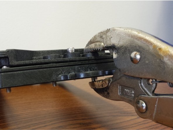
Using a pair of vise-grip pliers, c-clamp, or an extra set of hands, apply pressure near the middle of one of the short edges of the assembly (be sure not to cover up the counter-bore for the 6-32 x 5/8" Socket Head Cap Screw)
-
With the pieces clamped together insert a 6-32 x 5/8" Socket Head Cap Screw into each of the hole in the centers, and nylon lock nuts in the corresponding nut traps. DO NOT TIGHTEN just engage the threads into the nylon lock nuts.
-
Install the final two (2) 6-32 x 5/8" Socket Head Cap Screws in the remaining locations on the long edge of the assembly. You can now tighten the (6) 6-32 x 5/8" Socket Head Cap Screws in a star like pattern
-
This completes the assembly of the Flexible Resin Reservoir. Set this sub-assembly aside until later in the build.
-
-
-
Attach the Mirror Mount Side to the Mirror Mount as shown in the video, pay particular attention to the part orientation.
-
There should be one spacer installed in between the Mirror Mount Side and the Mirror Mount.
-
The fasteners should be not be fully tightened. After the Mirror Mount is fully assembled you can tighten these screws up to the point that they are tight, but still allow the mirror to pivot.
-
-
-
-
Attach the previously assembled Mirror Mount (Left) and (Right) Sides to the Cross Brace and Center Brace as shown in the animation.
-
NOTE: You should have tapped the 2 holes in the Cross Brace as part of the Preparing For the Build Steps. If you have not done that yet, please do so now before proceeding.
-
NOTE:These pieces are a tight fit. You will need to "walk" the left and right sides onto the cross brace. FURTHER: You will need to install both of the Cross Brace and Center Brace at the same time, otherwise you will only be able to install 1 of the 2 parts.
-
Do NOT tighten these screws.
-
-
-
-
Use the remaining 6-32 x 1" Phillips Pan Head Screw to attach the base to your current assembly.
-
You can now fully tighten all screws in the assembly.
-
NOTE: The two screws that act as a pivot point should not be so tight as to prevent the Mirror Mount Assembly top section from pivoting about the bottom section.
-
Set the entire sub-assembly and remaining parts from this sub-assembly aside for installation later in the build.
-
-
-
-
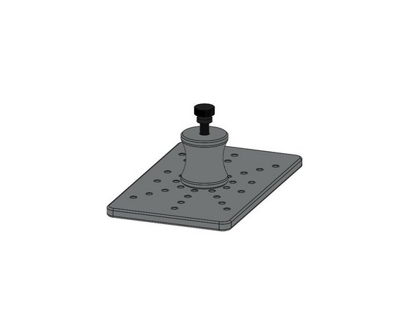
Locate the Projector Plate, Projector Joining Plate, (3) 6-32 x 1" Phillip Pan Head Screws, (3) Nylon Lock Nuts, (3) Plastic Bearings, (4) Legs, (4) Rubber Feet, (4) 10-32 x 5/8" Pan Head Nylon Screws, and (4) 10-32 Finish Nuts.
-
Assemble the components as shown in the animation video.
-
NOTE: Be sure to get the correct orientation of the Projector Plate (the engraved text indicates the TOP) and Projector Joining Plate.
-
Tighten all fasteners.
-
-
-
Locate the Base Plate, (4) 6-32 x 1" Phillip Pan Head Screws, (4) Nylon Lock Nuts, (4) Legs, (4) Rubber Feet, and (8) Leg Standoffs.
-
Assemble the components as shown in the animation video.
-
NOTE: Be sure to get the correct orientation of the Base Plate (the engraved lines running from the left to right near the front center of this plate indicates the TOP)
-
-
-
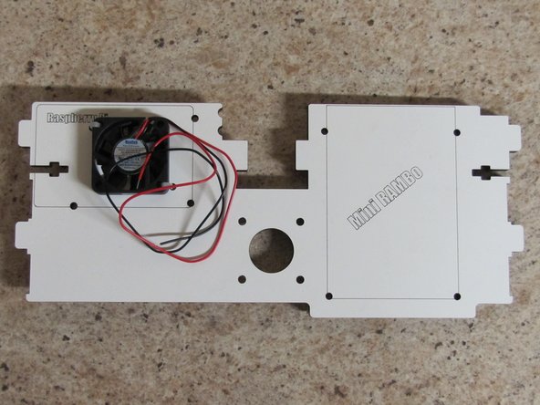
Locate the Motor Plate and 40mm fan.
-
You will be mounting the 40mm fan to the top of the Motor Plate using 2 zip ties, one on the upper left and one on the lower right corners of the fan.
-
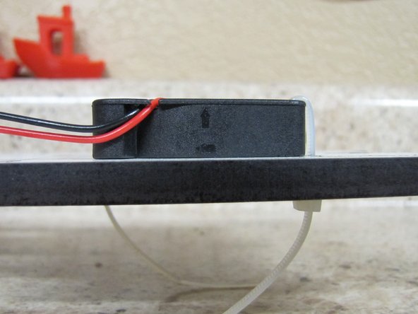
The fan should be mounted in such that the air will flow upwards (see image) and the wires will come off of the top of the fan and towards the back of the Motor Plate.
-
-
-
Note: The fan was installed in Part 1 of Prepping the Motor Plate.
-
Locate the (7) Board Supports and (7) #6 x 1/2"L Phillip Pan Head Screws.
-
You will attach the Board Supports to the Motor Plate as shown in the animation.
-
You can fully tighten these as you go.
-
-
-
Locate the following Parts: Left Side Panel, Right Side Panel, Base Plate, Vat Plate, Motor Plate, (2) Acrylic Side Windows, (10) 6-32 x 1" Phillips Pan Head Screws, and (10) 6-32 Nylon Lock Nuts.
-
NOTE: The Left Side Panel has a protrusion that extends out from the front edge and the Right Side Panel has 3 slots in the front that cut back towards the side window.
-
NOTE: Pay particular attention to the orientation of the remaining parts in the assembly animation.
-
Assemble the mid section parts to the Left Side Panel first and then to the Right Side Panel.
-
Do NOT fully tighten the screws at this time.
-
-
-
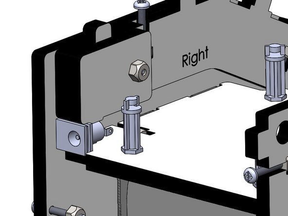
Locate the Upper Plate Mount Right, Upper Plate Mount Left, Barrel Connector Hold-down, (4) 6-32 x 1" Phillips Pan Head Screws, and (4) 6-32 Nylon Lock Nuts.
-
Attach the Upper Plate Mount Right and Left pieces according to the animation.
-
NOTE: The orientaion of these pieces is critical. When installed their labels of RIGHT / LEFT should still be visible.
-
-
-
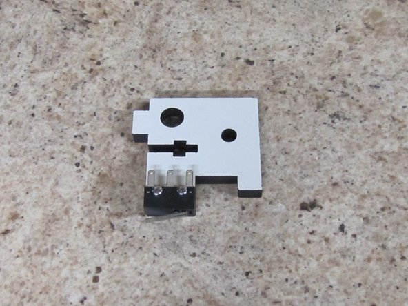
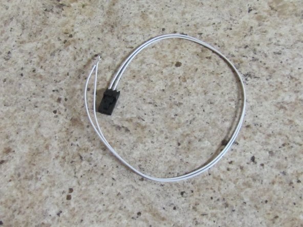
Locate (1) of (2) Upper TSLOT Mounts, (2) 2-56 x 5/8" Pan Head Machine Screws, (2) 2-56 Finish Nuts, and Pre-terminated End Stop Wires.
-
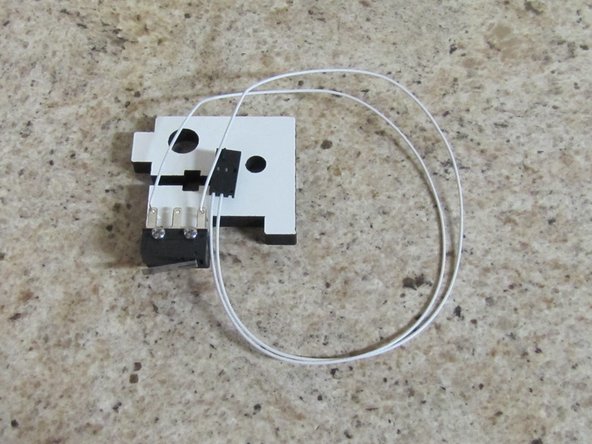
Attach the Limit Switch to the Upper TSLOT Mount as shown in the picture using the 2-56 hardware.
-
Solder the End Stop Wires (two white wires with a 3 pin connector on one end) to the outer two legs of the limit switch as shown in the image.
-
-
-
Since we already have the soldering iron heated up, lets get the rest of the solder connections out of the way.
-
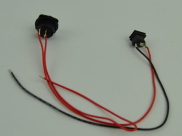
Locate the (2) 18awg x 300mm RED wires, (1) 18awg x 300mm BLACK, (1) Barrel Jack Connector, and (1) Rocker Switch
-
Solder both of the red wires to the legs of the Rocker Switch
-
Solder the other end of one of the red wires to the top (next to the round) of the barrel connector.
-
Solder the black wire to the bottom of the barrel connector.
-
NOTE: The middle pin on the barrel connector is not used.
-
Your finished product should look like the image on the left. Set it aside for installation later.
-
That is all the soldering for the entire kit.
-
-
-
Locate the (2) Upper TSLOT Mounts, (2) Lower TSLOT Mounts, (4) 1/4-20 x 1/2" Button Head Cap Screws, and (4) TSLOT Nuts.
-
Attach the 1/4-20 x 1/2" Button Head Cap Screws, and TSLOT Nuts to the Upper and Lower TSLOT Mounts first,
-
DO NOT TIGHTEN THE SCREWS BEYOND JUST GETTING THE THREADS TO ENGAGE.
-
Place the Upper and Lower TSLOT Mounts on the frame assembly you have been working on as shown in the animation. The Upper TSLOT Mount with the limit switch attached will be installed on the LEFT side. You will see the notches in the motor plate which are clearance for the 2-56 screws.
-
-
-
Locate the Back Plate, (6) 6-32 x 1" Pan Head Phillips Screws, and (6) 6-32 Nylon Lock Nuts.
-
Install the Back Plate on the assembly
-
Note: By installing the Back Plate this will square up the frame of the machine. You will removing this panel in future steps for further part installation.
-
Tighten the 6 screws that join the Left / Right Panels to the Back Plate
-
Tighten the screws that join the Left / Right Side panels to the Base Plate, Vat Plate, and Motor Plate (10 total screws)
-
-
-
Locate the TSLOT and the Carriage Assembly (Assembled in a previous section)
-
Begin by installing the TSLOT down through the top of the Upper TSLOT Mounts. You must have the TSLOT nuts Oriented so that they will go into the slot of the TSLOT.
-
After the TSLOT has passed through Motor Mount Plate by approximately 4", align the Carriage Assembly and gently push the TSLOT down through the carriage.
-
Continue to pass the TSLOT down into the Lower TSLOT Mounts until it is flush with the botto surface of the VAT Plate.
-
Tighten the 1/4 -20 x 1/2" Button Head Screws fully securing the TSLOT.
-
-
-
Locate the M10 x 2 x 200mm Trapezoidal Lead Screw, 5mm Shaft Coupler, (4)M3 - .5 x 3mm Set Screws, and M3 Allen Wrench
-
Insert the Set Screws into the Shaft Coupler. Tighten the set screws approximately half their length into the Shaft Coupler.
-
Attach the 5mm Shaft Couple to the Trapezoidal Lead Screw. It is best to twist either component while inserting the two items together.
-
Seat the Shaft Couple Fully onto the Trapezoidal Lead Screw and tighten the (2) set screws completely.
-
Insert the Trapezoidal Lead Screw through the hole in the Motor Plate and rest it on the Anti-Backlash nut on the carriage.
-
Place downward pressure on the Anti-Backlash collar and at the same time turn the Trapezoidal Lead Screw clockwise while pushing downwards to engage the threads on the two components.
-
Once engaged, continue turning the Trapezoidal Lead Screw until you have approximately 2" extended below the bottom of the carriage assembly.
-
-
-
Locate the NEMA 17 Stepper Motor and (4) M3-.5 x 10mm Phillip Pan Head Screws.
-
Orient the NEMA 17 Stepper Motor with the wires exiting the body of the motor to the right. Attach the motor to the Motor Plate.
-
Tighten the screws completely.
-
Lift the Carriage Assembly and Trapezoidal Lead Screw(set screw facing the front of the machine), inserting the stepper motor shaft (flat facing the front of the machine) into the shaft coupler.
-
With this in position, tighten the (2) set screws onto the stepper motor shaft. ENSURE THAT ONE OF THE SET SCREWS IS LANDING ON THE FLAT OF THE STEPPER MOTOR SHAFT.
-
Turn the Trapezoidal Lead Screw clockwise until you hear the limit switch engaged by the carriage.
-
Carefully lay the machine on its back and tighten the (3) #4 Phillips Pan Head Screws into the Anti-Backlash Nut. ENSURE THAT YOU ARE NOT APPLYING ANY PRESSURE TO THE TRAPEZOIDAL LEAD SCREW. YOU WANT THE LEAD SCREW TO SELF ALIGN WITH THE ANTI-BACKLASH NUT AND SECURE IT IN THAT POSITION.
-
-
-
Locate the Upper Hinge Mount, (3) Hinges, (4) 6-32 x 1" Pan Head Machine Screws, (4) 6-32 Nylon Lock Nuts, (3) 2-56 Finish Nuts, and (3) Plastic Bearings.
-
Insert the (3) 2-56 Finish Nuts into the Hinges (similar to how you inserted the 6-32 Nylon Lock Nuts into the but traps for the rest of the frame).
-
Attach the components as shown in the animation, starting with the Hinge Mount.
-
NOTE: You should not over-Tighten the the three screws that act as the pivots or else the door will not easily open / close. Loosen these screws if you find that he hinge does not easily open / close.
-
-
-
Locate the Front Acrylic Door, Door Handle, and remaining 2-56 Finish Nut, and (4) 2-56 x 5/8" Phillips Pan Head Screws.
-
Insert the 2-56 Finish Nut into nut trap in the Door Handle.
-
Install the Acrylic Door as shown in the animation. Secure the door with the 2-56 x 5/8" Phillips Pan Head Screws.
-
Attach the Door Handle to the Acrylic Door as shown in the animation.
-
TO PREVENT CRACKING THE ACRYLIC DOOR, DO NOT OVER-TIGHTEN THE SCREWS.
-
-
-
Locate the Mini-RAMBo board, Raspberry Pi 3 board. Rocker Switch / Barrel Connector (previously soldered), and 5v wire harness.
-
Remove the pack panel from the machine (don't forget to remove the 6-32 x 1" Phillips Pan Head Screws holding it in place).
-
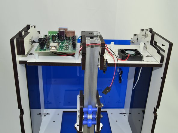
You will be Installing l the Mini-RAMBo and Raspberry Pi in the top of the DropLit. You must have the Board Supports in the correct orientation so that the board will slide into the board retention area.
-
For the Mini-RAMBo, the board supports closest to the back of the Droplit v2 will be catching the sides of the board and the Board supports closest to the front of the machine will be catching the corners of the board.
-
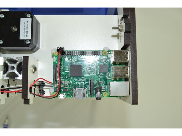
For the Raspberry Pi 3, two board supports will be catching the edges of the board and one will be catching the corner.
-
The animation shows how the boards are oriented and inserted into the machine. The pictures in the next step(s) show how to "tame" the wires and where to connect them.
-
-
-
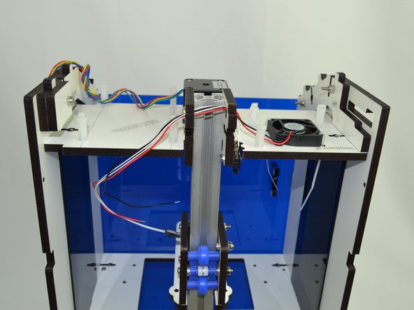
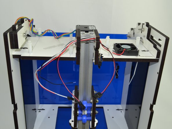
Route the fan and endstop wires through the holes located in the top corner of the Upper TSLOT Mounts.
-
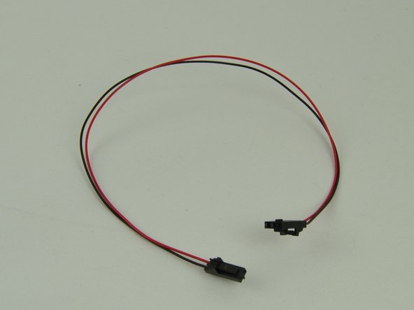
Route the 5v Wire Harness through the same holes. The three pin connector needs to be on the side closest to the fan.
-
-
-
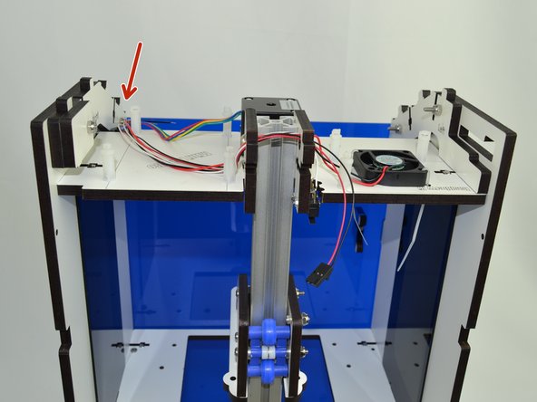
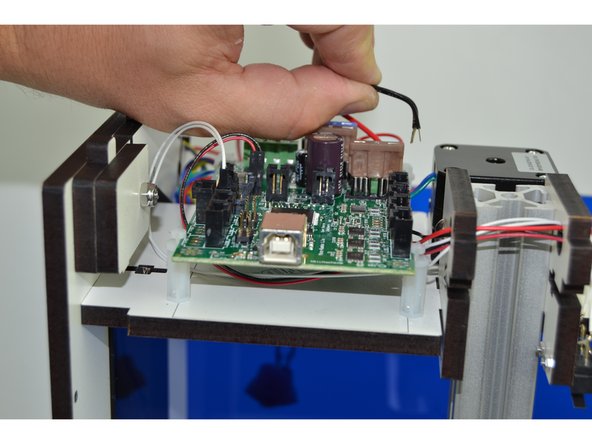
Tuck the wires on the side that the Mini-RAMBo will go next to the post as indicated. This will keep the wires out of the way of the board support while inserting the board.
-
Slide the Mini-RAMBo board into position.
-
-
-
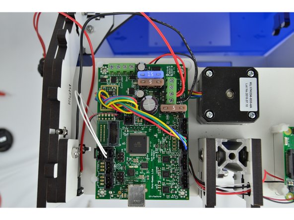
Make the following wire connections:
-
18awg RED wire from the Rocker Switch & RED fan wire connects to Power Input - Primary - Positive (+)
-
18awg BLACK wire from the Barrel Connector & BLACK fan wire connects to Power Input - Primary - Negative (-)
-
NEMA 17 Stepper Motor wires will connect to the Z axis driver. (NOTE: The red wire should be closest to the 15amp fuse)
-
End Stop wires connect to the Z-Max
-
2 pin connector from the 5v Wire Harness will connect to X1 on the Mini-RAMBo and the 3 pin connector will connect to pins 4 &6 on the Raspberry Pi (Pi pinout: http://tinyurl.com/mtwp3kj) (NOTE: the 2&3 pin connectors MUST BE PLUGGED IN BASED ON THE ORIENTATION IN IMAGE)
-
-
-
Push the Barrel Connector into the pocket show in the image. Once the Back Plate is installed this will fully constrain the connector.
-
You are now ready to re-install the the Back Plate. Use the (6) previously used 6-32 x 1" Pan Head Phillips screws plus two additional of the same type of screw through the Base Plate.
-
-
-
Locate the Skylight, Acrylic Skylight and (4) 6-32 x 1" Pan Head Phillips Screws.
-
Lay the Acrylic Skylight into the recesses on the sloped portion of the frame.
-
Install the Skylight and secure using (2) 6-32 x 1" Pan Head Phillips Screws. Fully Tighten
-
You can set the Top Plate in position but do not fully tighten. We must image the SD card and install it in the Raspberry Pi 3 before the top is fully buttoned up. (This will be done in a separate Guide). After that SD has been installed you can secure the Top Plate.
-
-
-
Using the supplied 10-32 Knurled Thumb screws, you will now install the Mirror Mount and VAT.
-
The Mirror Mount should point the Mirror toward the back of the printer and is secure to the Base Plate with (2) 10-32 Knurled Thumb screws
-
The VAT should have the spill spout in the back of the printer.
-
There are (3) 10-32 Knurled Thumb screws that go up through the VAT Plate that are used to level the VAT. (2) additional 10-32 Knurled Thumb screws will secure the VAT.
-