
Introduction
This guide will show you how to assemble the HE280 hot end and effector platform. Note that these instructions only cover the HE280 as shipped during and after March of 2018.
If you're not sure when your HE280 was shipped, you can easily tell. The pre-March 2018 units have a thermal fuse and the thermistor is a glass bead. The newer HE280's have a cartridge-encapsulated thermistor and no thermal fuse.
Tools
Parts
No parts specified.
-
-
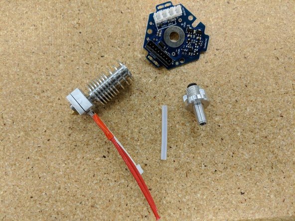
This step requires the Rev6 HE280 probe board and a JST connector, as shown in the far left image.
-
You'll need to flip the board upside down and locate the position marked "TEMP". This is the position where you'll be soldering the JST connector.
-
Insert the JST connector into the board with it's notch facing the printed notch on the PCB. Solder in place.
-
-
-
For this task you'll need the heater cartridge and crimps included in the kit.
-
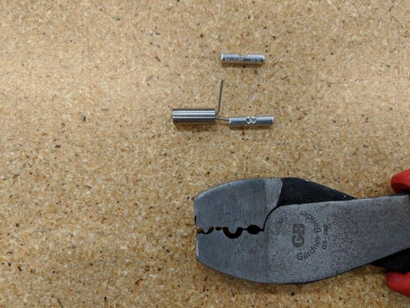
Cut the legs of the heating cartridge to 11 mm.
-
Bend one leg of the cartridge 90 degrees away from the other leg. This will seperate them giving room to attach the crimp terminals.
-
-
-
If you have a pair of crimps like the one in the picture, this will help. The first position near the tip of the crimps pictured are used in this step.
-
Place the first crimp on one leg of the cartridge. The leg of the cartridge will go to the mid point of the crimp shown.
-
Use the crimp tool to crush the HALF of the crimp that the leg of the cartridge is in. DO NOT crimp the entire length of the crimp as the wire will go in the other half.
-
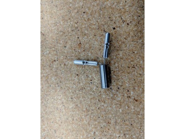
Repeat the process on the other leg of the cartridge so both crimps are attached to the heater cartridge.
-
-
-
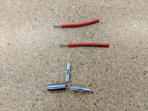
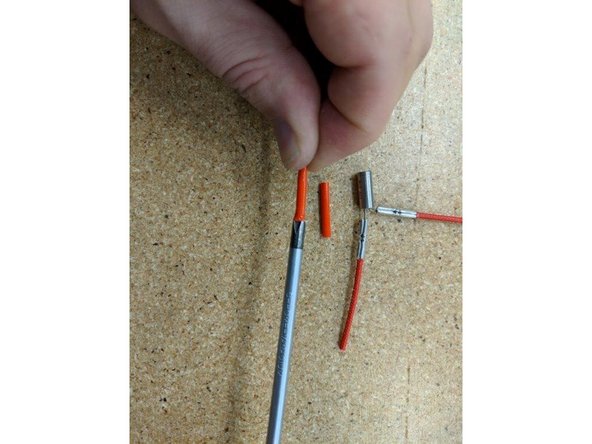
Locate the two red insulated wires in the kit and strip off the ends as shown in the first picture approximately as long as half the crimp. 7 mm works fine.
-
Insert the wires into the crimps and as in the step before use your crimp tool or pliers to crush the other half of the crimp attaching the wires to the crimp securely.
-
-
-
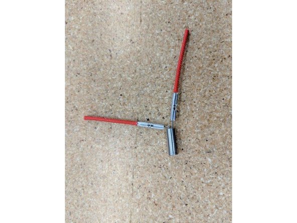
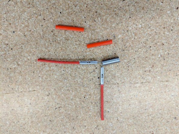
Locate the red silicone tube from the kit. Cut this tube in half so you have 2 pieces of equal length.
-
Use a screwdriver on one end of a tube to help open up one side. This will help get the tube over the crimps you just installed.
-
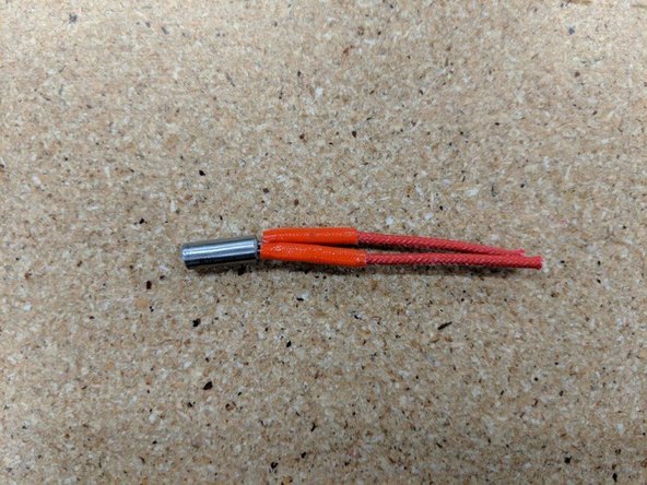
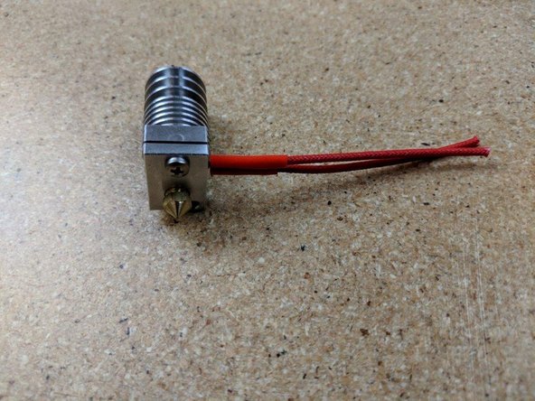
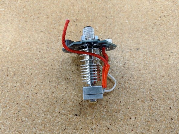
Slide one tube on one of the wires and work it down over the crimps until fully seated near the heater cartridge. Repeat this process on the other leg of the heater. The previous 11mm and 7mm cut lengths will give a result as in Pic 3.
-
Bend the leg of the cartridge so they are back in line with the cartridge. Pic 3 shows a fully prepped heater cartridge.
-
-
-
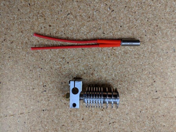
The main body of the hotend will come finger tight. Do not use this as assembled.
-
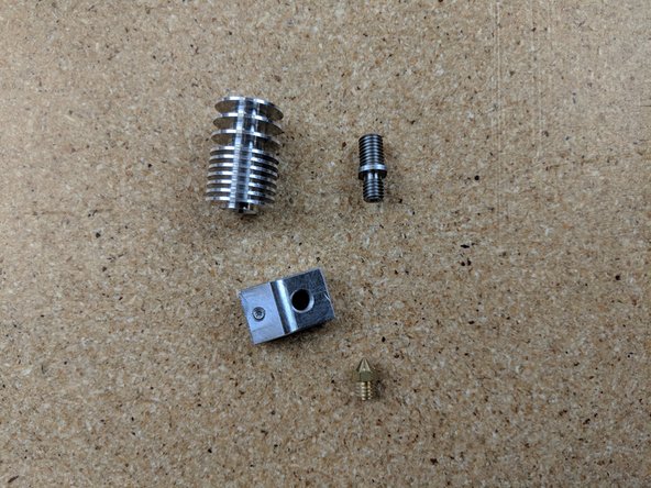
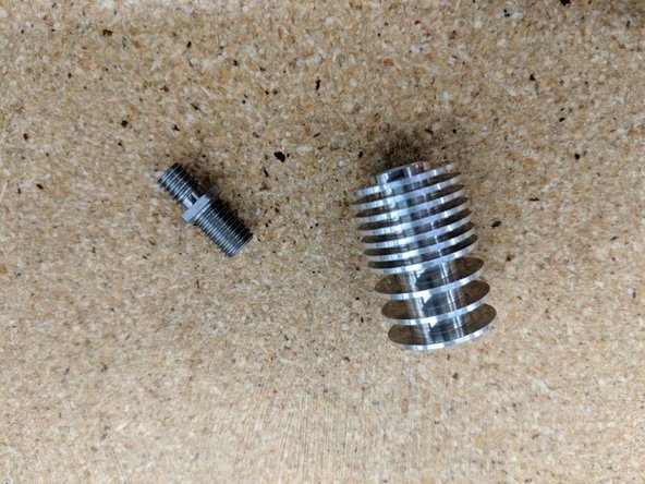
First remove the nozzle (should only be on finger tight when taken from the kit). Then unscrew the heater block. Finally unscrew the heat break. You should have 4 seperate pieces.
-
You should have the body disassembled as shown in Pic 2.
-
-
-
Locate the heat sink and heat break from the parts you just dissembled in the previous step.
-
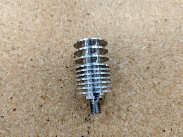
Screw the heat break into the heat sink into the side with multiple closer fins as shown in pic 2.
-
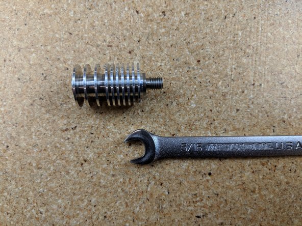
The heat break has 2 flats on it used to tighten it. Use a 5/16 wrench or an adjustable wrench and securely tighten the heat break to the heat sink.
-
-
-
Locate the heater block, nozzle, and heatsink body you just disassembled.
-
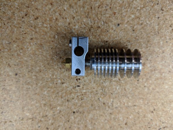
Screw the heat break and heatsink into the heater block watching the threads of the heat break until the end of the threads are just about even with the the heater block.
-
The heat sink screws into the heat block into the side opposite the screw that clamps the heat cartridge.
-
Screw the nozzle into the heater block on the side with the screw and set screw as shown in pic 1.
-
Use an adjustable wrench or 6mm socket to tighten the nozzle. The nozzle tightens against the heat break to create a seal inside the heater block.
-
-
-
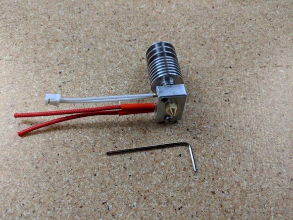
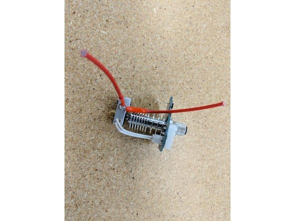
Insert the heater cartridge into the heater block. The wires from the heater cartridge should exit the same side the set screw is on that holds the thermistor in place.
-
Tighten the screw to secure the heater cartridge in place. You can use pliers to hold the block in place while tightening the screw.
-
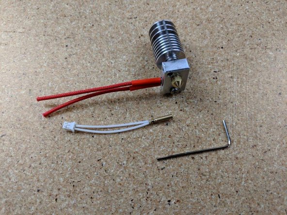
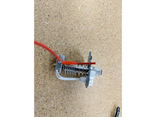
Locate the thermistor cartridge and allen key.
-
Insert the thermistor FULLY (you may need to loosen or remove the setscrew that is pre-installed so the thermistor cartridge can be fully inserted.
-
Use the allen key to tighten the set screw to hold the thermistor in place.
-
DO NOT OVERTIGHTEN the set screw for the thermistor. Once the set screw is snug, you only need to turn about 1/2 turn beyond to tighten. Over tightening can damage the thermistor
-
-
-
For this task, you'll need the Hot End Assembly, the Probe PCB, and the Locking PTC Adapter.
-
The Locking PTC Adapter has a PTFE tube in it. Remove the tube from the adapter before you begin.
-
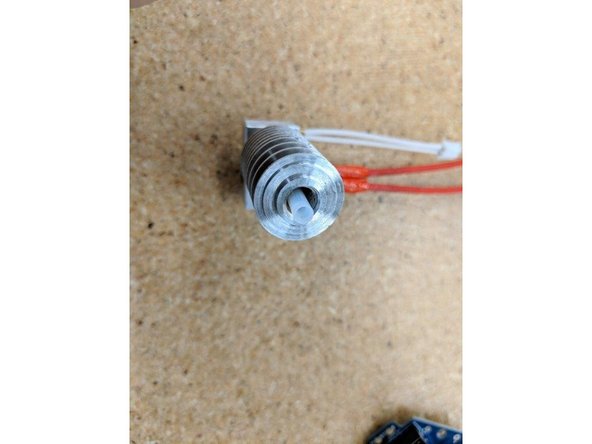
Insert the PTFE tube into the top of the heat sink until only 4 or 5mm are exposed at the top.
-
The PTFE tube has a taper on one side of it. This side should face the top of the heatsink on the side with the circuit board.
-
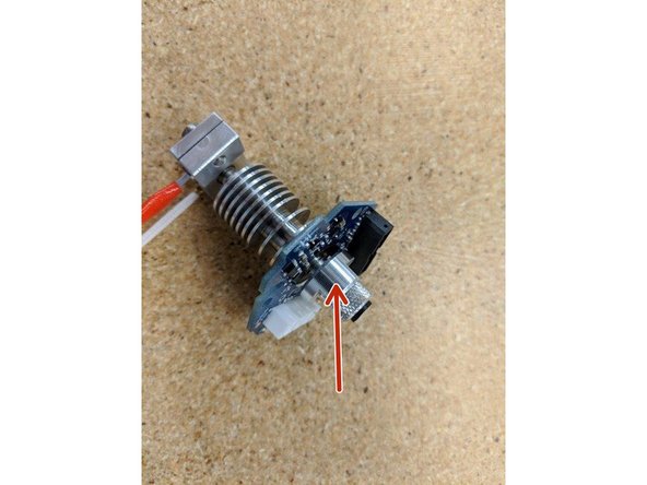
Center the Probe Board on top of the heat sink with the bottom JST connector aligned with the thermistor and install the threaded Locking PTC Adapter. When you install the adapter, thread it in slowly - stop when you feel the adapter begin to compress the PTFE tubing.
-
Fix the PCB and Hot End together by tightening the locking nut as indicated by the red arrow. Tighten with the blue plastic HE280 PTC tool (not shown).
-
-
-
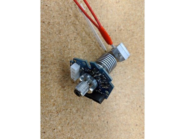
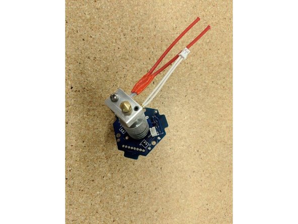
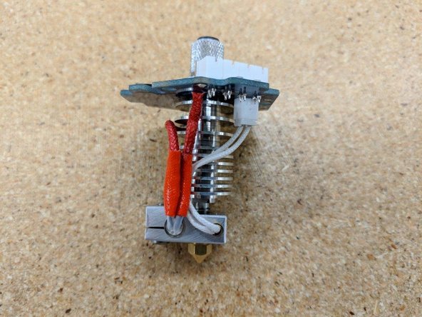
Insert the Thermistor connector into the JST connector on the bottom of the Probe PCB.
-
-
-
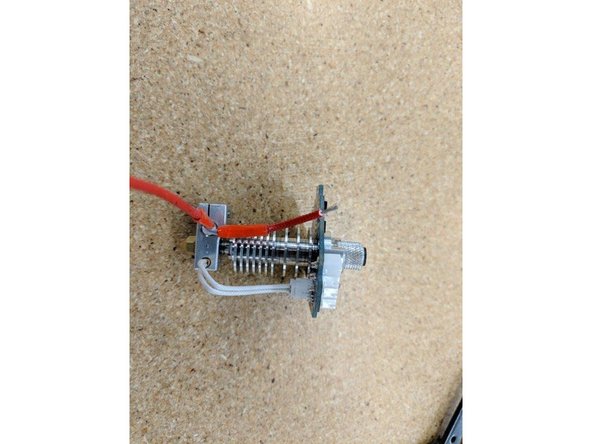
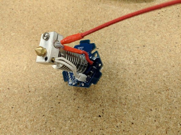
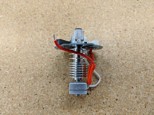
Trim one heater cartridge wire so that it extends past the top of the PCB by about 6mm as shown in the photos.
-
Strip ~4mm of insulation from the lead you just trimmed.
-
-
-
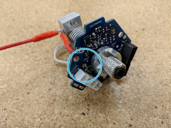
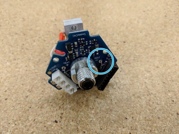
Insert the stripped lead into the position marked "HEAT +" as indicated by the blue circle.
-
Route the second heater cartridge lead as shown.
-
-
-
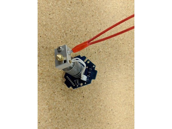
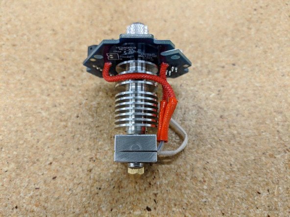
Trim the second lead so that it extends past the PCB by about 6mm when in the position shown.
-
Strip ~4mm of insulation from the lead.
-
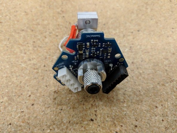
Insert the stripped lead into the location marked "HEAT -" as shown by the blue circle.
-
-
-
Finally, solder the heater cartridge leads to the Probe PCB.
-
-
-
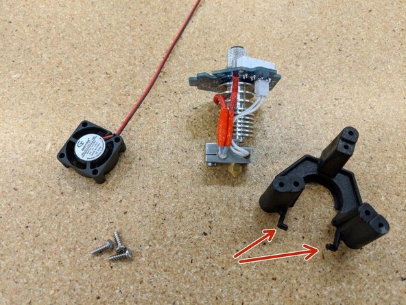
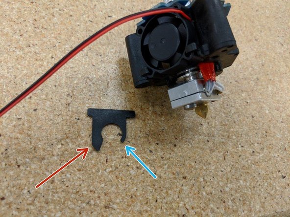
For this task, you'll need the assembled hot end, the HE280 PCB Mount, 3 #4, 3/8" screws, 1 Barrel Fan Blocker, and 1 25mm fan.
-
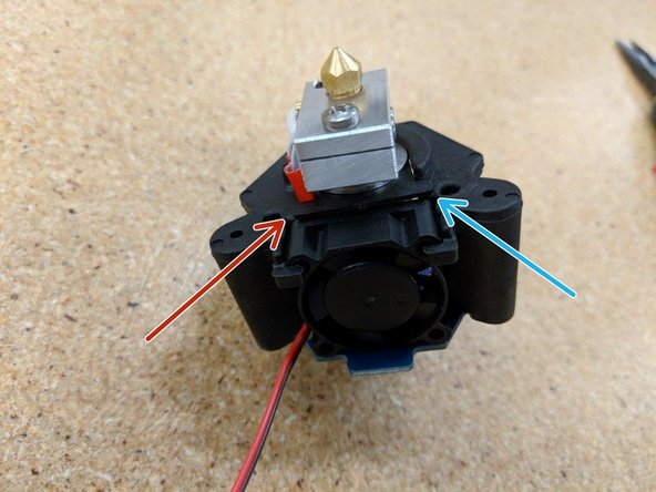
Insert the hot end assembly into the HE280 PCB Mount so that the tab with "SeeMeCNC" on it is aligned with the cooling fan retaining clips (identified by the red arrows).
-
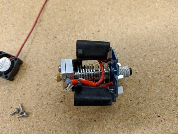
Install the cooling fan into the retaining clips, under the HE280 PCB. The fan blades should face away from the hot end, as shown.
-
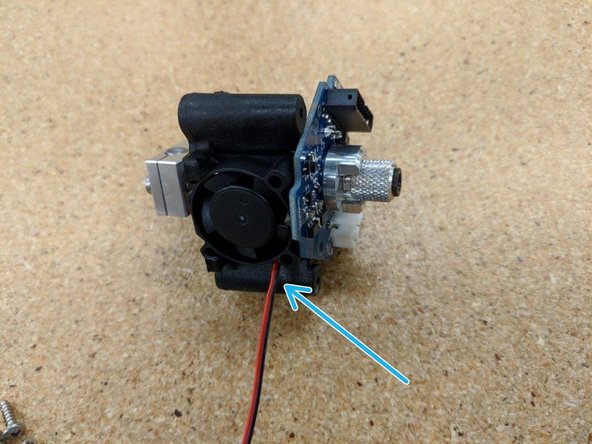
Make sure that the power lead for the fan is in the upper right corner of the fan as indicated by the blue arrow.
-
-
-
Insert the barrel fan blocker between the last two heat sink fins at the bottom of the hot end.
-
Install with the long leg of the blocker on the left (red arrow) and the short leg of the blocker on the right (blue arrow). You'll feel the blocker "snap" into place when it's properly seated.
-
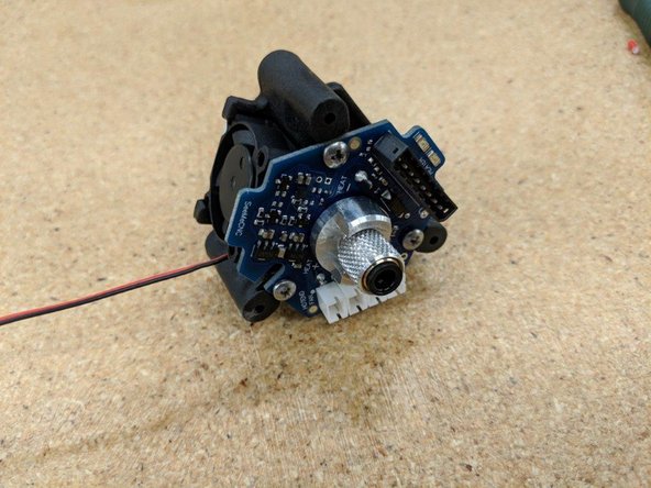
Attach the PCB to the HE280 PCB Mount using three #4 x 3/8" screws as shown.
-
-
-
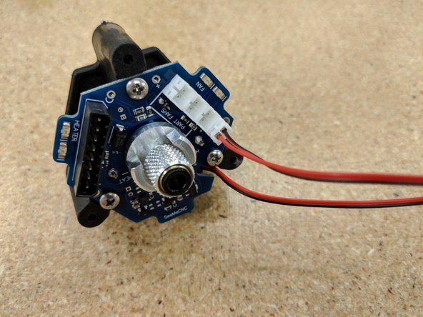
Connect the hot end fan to the JST connector on the far right of the PCB as shown.
-
-
-
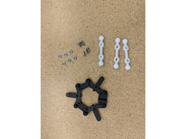
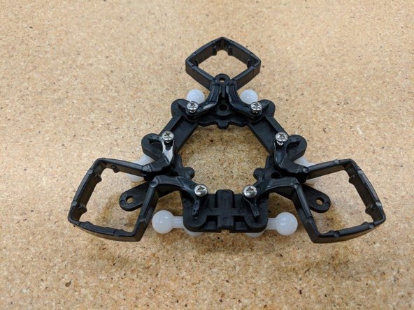
For this task, you'll need the effector platform, three ball joint arms, six #4, 3/8" screws, and size #4 washers.
-
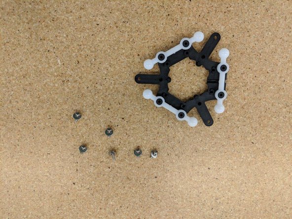
Press each ball arm over the mounting posts on the effector platform.
-
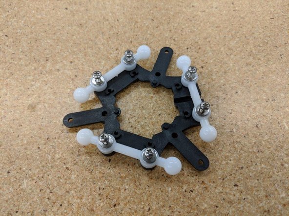
Fix each ball arm into place using two #4, 3/8" screws and two washers.
-
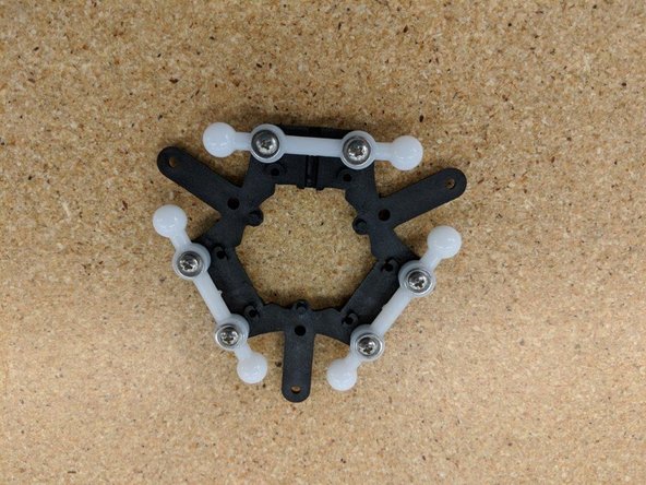
The completed assembly should look like the example in the last photo.
-
-
-
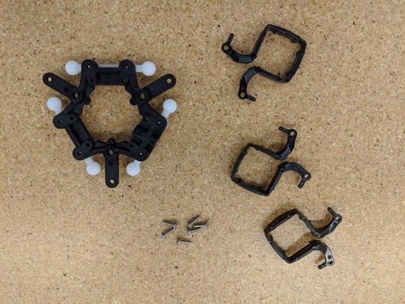
For this task, you'll need the three layer fan mounting brackets, the assembled effector platform, and six #4, 3/8" screws
-
Fix each fan bracket in place using two #4, 3/8" screws for each one. DO NOT TIGHTEN . The screws will be tightened down in a later step.
-
Pay close attention to how the fan brackets are oriented. They should be installed exactly as shown in the last image.
-
-
-
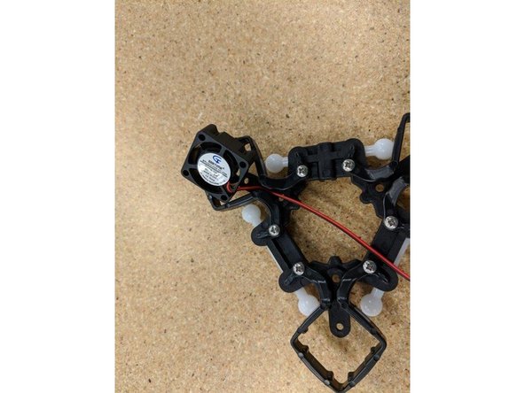
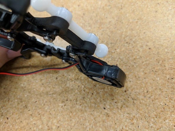
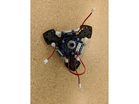
Insert one layer fan with the fan label facing away from the ball arm, as shown.
-
Make sure to carefully route the power wires for the fan as they are in the images.
-
-
-
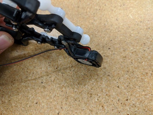
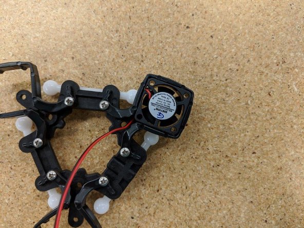
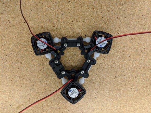
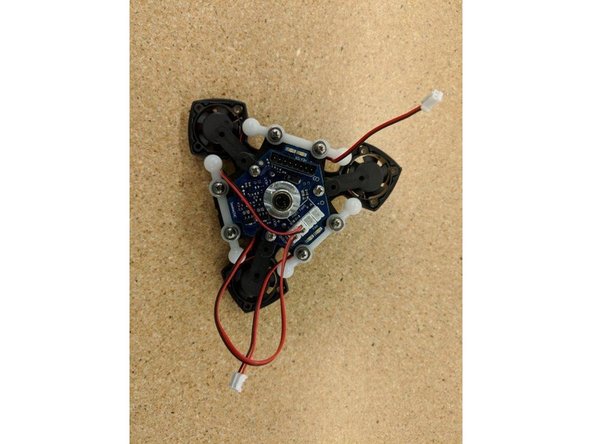
Install the other two layer fans, paying careful attention to their orientation (label away from the ball arm) and the wire route.
-
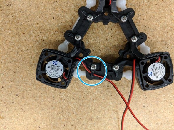
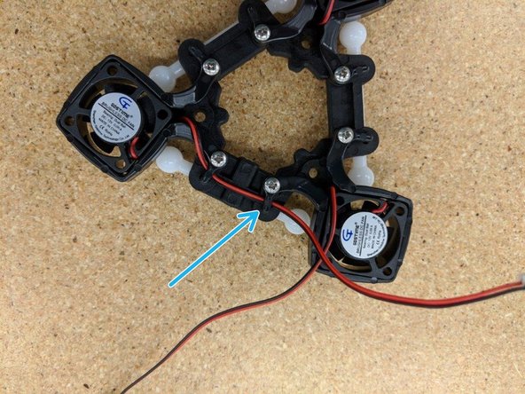
Looking down at the effector platform, route the left fan's wires through the clip at the end of the mounting bracket as indicated by the blue circle.
-
-
-
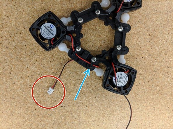
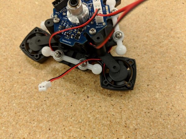
Finish routing the left fan's wire by running it under the clip next to it (blue arrow) and then fold the lead under the effector (red circle).
-
Tighten down the two screws that capture the fan lead you're working with. Take special care not to crush the fan wire under the clip - make sure it is routed under the clip arch itself.
-
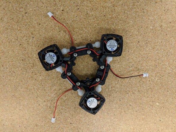
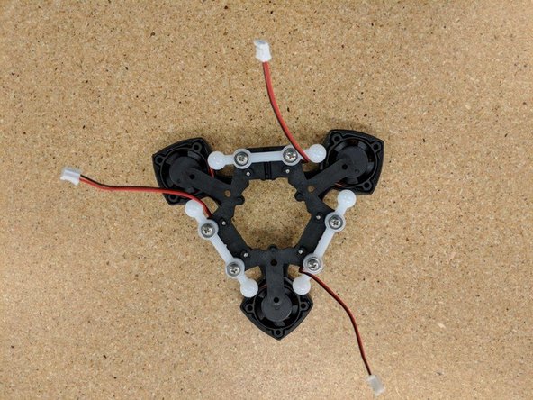
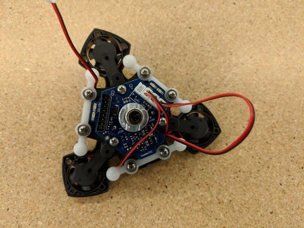
Perform these tasks for the two remaining fans.
-
-
-
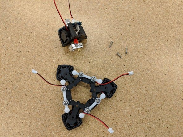
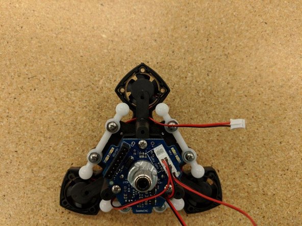
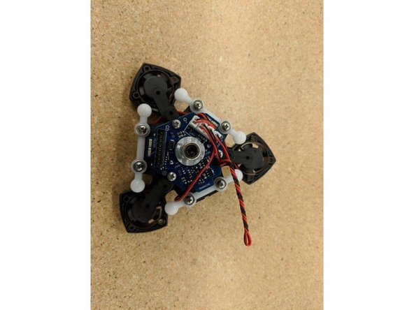
For this task, you'll need the assembled effector platform, the hot end assembly, and three #4, 1/2" screws.
-
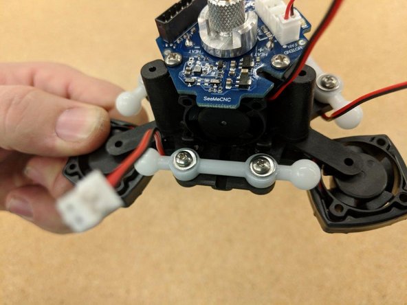
Place the hot end assembly into the center of the effector platform.
-
-
-
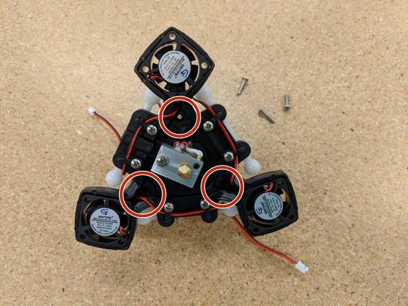
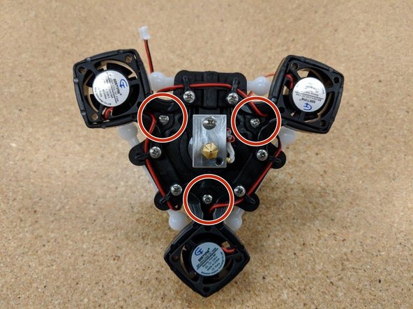
Using the three #4, 1/2" screws, fix the hot end assembly to the effector platform at the locations indicated by the red circles.
-
Take special care not to trap a fan lead under a screw head!
-
-
-
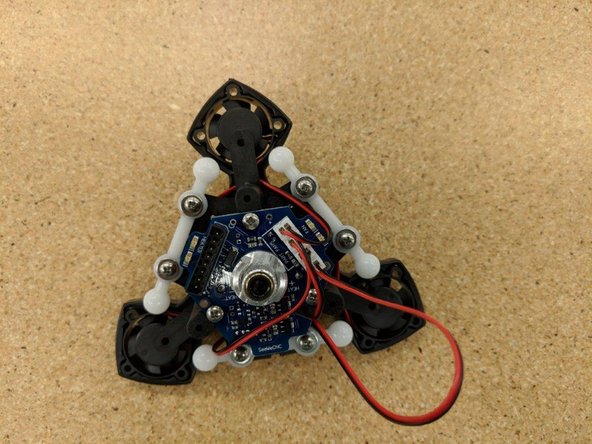
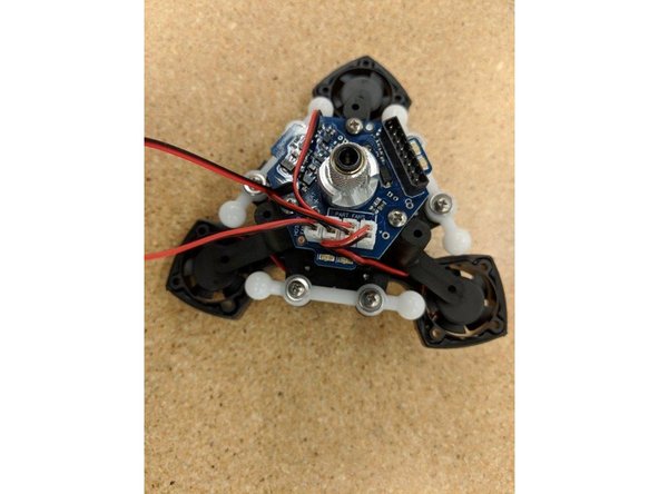
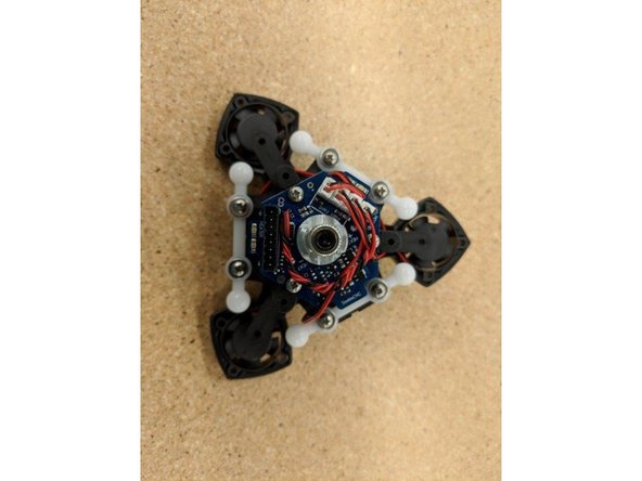
Route the fan leads as shown and plug into the JST connectors at the top of the PCB.
-
-
-
As you connect each fan wire, route the wire as shown in the photos.
-
-
-
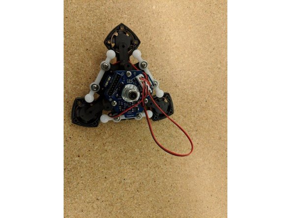
Take the large loop of fan wire, fold it in half and carefully spindle it as shown.
-
Wrap this spindled fan wire around the PTC Locking Adapter as shown.
-
-
-
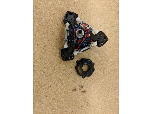
For this task you'll need three #4, 3/8" screws and the HE280 Top Cover
-
Align the top cover so that the 8 pin connector fits through the slot in the top of the cover.
-
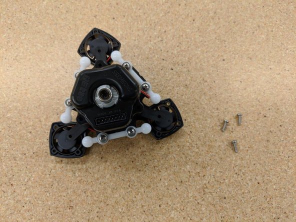
Fix into place using three #4, 3/8" screws.
-
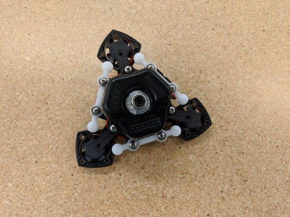
Congrats! You're done with the HE280 Hot End assembly!
-


Cancel: I did not complete this guide.
One other person completed this guide.