Tools
-
-
The new platform design requires that you print both a new PEEK and Layer fan shroud. Print both of these now, BEFORE you tear your printer apart. :)
-
The PEEK fan shroud can be found here: PEEK FAN SHROUD
-
The Layer fan shroud can be found here: LAYER FAN SHROUD
-
-
-
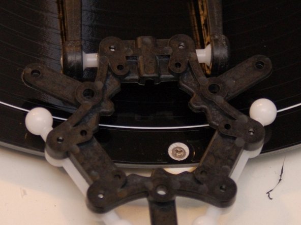
Press a Ball Joint Arm on to two of the mounting posts on the under side of the Ball Joint Platform.
-
Fix in place using two #4, 3/8" sheet metal and two #4 flat washers.
-
Repeat for the other two mounting locations as shown in the third image.
-
-
-
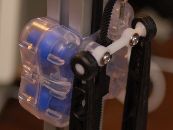
Attach a Ball Joint Arm to the ball joints on the carriage as shown. As you press the socket over the ball on the carriage, you'll hear a faint "click" as it locks into place.
-
Attach the Ball Joint Platform you assembled previously to the other ends of the arms as shown.
-
If you're using a hot end other than the older one shown in this guide, you may want to install the effector platform with the ball-arms facing up. This will provide additional clearance between the effector platform and the heated bed, which is required by some hot end designs like the HE280 or E3D v6.
-
-
-
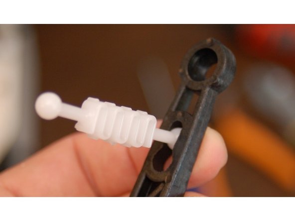
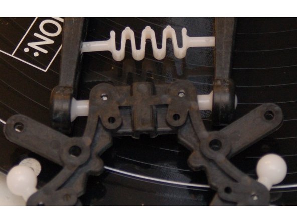
Insert the end of the tension spring into the keyhole notch in the arm as shown.
-
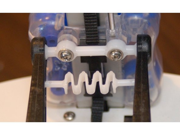
Gently stretch the spring across to the opposite arm and latch it into the keyhole notch.
-
Perform this step at both tension spring locations - the "top" end at the carriage and the "bottom" end at the Ball Joint Platform.
-
Repeat this and the previous step for the other two pairs of arms.
-
-
-
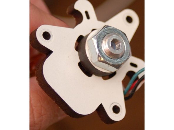
Remove the hot end from the old-style platform and install it into the new style.
-
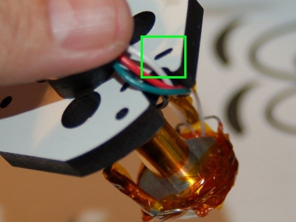
Tie the wires to the strain relief using a 4" wire tie in the notch shown.
-
Install the hot end on to the new platform.
-
This new arm upgrade has significantly changed the geometry of the printer. Because of this, you'll need to recalibrate. In order to do this successfully, you'll need to change your Horizontal Radius to 140 (if you haven't already) and the Diagonal Rod length to 290.8.
-
If you're upgrading an Orion, you'll want to set the Horizontal Radius to 89 as a starting point. The Diagonal Rod length is 179.0
-
You're done!
-
Cancel: I did not complete this guide.
2 other people completed this guide.
9 Comments
Gene, in step 5 you reference to the next step, but there is no next step ;-) In the comment from Stephen above: I think he's is referring to the hotend mount, not to the platform. The hotend mount is the original one, and not included in the upgrade kit.
Con Hennekens - Resolved on Release Reply
Ah, gotcha. :) That's fixed. I'm surprised they're not including the adapter in the upgrade kits - they were when this was written.
geneb -
I didn't receive the piece that is pictured in Step 5 in the Orion Ball Joint Arm kit that we purchased, if that's what you're referencing as the "platform." I did receive a new molded plastic platform, which is necessary to attach the nylon ball connectors, and which fits the existing hot end mount. I would call the white laser-cut piece pictured a "top mount," or something similar, as the black molded plastic piece is already called a platform, and it is performing the function of a platform, which the piece pictured isn't, really. I do like the shape of the one pictured better than the existing one and would love to have a CAD file, as I don't know that I care enough about it to justify drawing it up so I could laser cut one of them.
Stephen Barner - Resolved on Release Reply
I followed this guide to install the new arms on a Rostock Max v2, however, now my effector isn't level when it is printing towards the edges of the build plate. This causes the fan shrouds and effector plate to scrape the build plate popping the print off the bed. I used the arm length of 290.8 from step 5, but it doesn't seem right. Any thoughts?
Michael Cummings - Resolved on Release Reply


