Difficulty
Moderate
Steps
4
Time Required

User-Contributed Guide
This guide is not managed by the site's staff.
Introduction
Injection Molded Vat Sub-Assembly
-
-
The parts for this sub-assembly are all packaged together. Locate this package labeled 78895 Universal Flexible Resin Reservoir.
-
Take extra care with the FEP film to prevent scratching either side. When not using the FEP film you should lay it on a non-scratch surface such as a paper towel or CLEAN shop towel.
-
The FEP sheet is pre-cut by SeeMeCNC and therefore has masking to protect the surface. Remove this mask by peeling off from one corner. Do not rush this process, you do not want to create any creases in the FEP film.
-
After you have removed the masking, lay the FEP film on a paper towel or CLEAN shop towel and use Isopropyl Alcohol to clean the surface of both sides. (Lens cleaning wipes would also work well)
-
-
-
You can see the order that the parts are assembled from the video. (1) Base, (2) FEP, (3) Tension Ring. They are all secured together using the supplied 6-32 x 1/2" Socket Head Cap Screws and 6-32 Nylon Lock Nuts.
-
Lay the FEP on top of the base plate. Ensure that you align the holes in the FEP with the holes in the base plate. (note: the nut traps in the Base Plate should be down against the table) Orientation of the FEP film does not matter, the part is symmetrical)
-
Lay the tension ring on top of the FEP. Ensure that you align the holes in the tension ring with the holes in the FEP and base plate. (Note this part is symmetrical in all aspects so orientation does not matter.)
-
Use (12) 6-32 x 1/2" Socket Head Cap Screws and (12) Nylon Lock Nuts to attach the tension ring to the FEP film and VAT base. Start with the four corners and then continue with the rest. Note the locations of the (12) 6-32 x 1/2" Socket Head Cap Screws in the animation.
-
Fully tighten all 12 of the (12) 6-32 x 1/2" Socket Head Cap Screws
-
-
-
For this installation, note the orientation in the animation (pour spout is in the back left corner and Thumb Screw retainers are pointing towards the back). This is not particularly critical, and is based on user preference. If you are assembling this for the DropLit v2, this will put the resin pouring spout in the back left corner (as designed)
-
Lay the VAT Top Plate on top of the FEP film. Insert (2) (12) 6-32 x 5/8" Socket Head Cap Screws into the holes on one of the long edges of the assembly. You will need to tilt the piece in order to get the screws started threading into the Nylon Lock Nuts.
-
You should only get the (2) 6-32 x 5/8" Socket Head Cap Screws starting to engage in the threads. DO NOT TIGHTEN
-
-
-
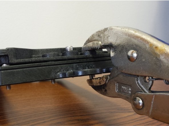
Using a pair of vise-grip pliers, c-clamp, or an extra set of hands, apply pressure near the middle of one of the short edges of the assembly (be sure not to cover up the counter-bore for the 6-32 x 5/8" Socket Head Cap Screw)
-
With the pieces clamped together insert a 6-32 x 5/8" Socket Head Cap Screw into each of the hole in the centers, and nylon lock nuts in the corresponding nut traps. DO NOT TIGHTEN just engage the threads into the nylon lock nuts.
-
Install the final two (2) 6-32 x 5/8" Socket Head Cap Screws in the remaining locations on the long edge of the assembly. You can now tighten the (6) 6-32 x 5/8" Socket Head Cap Screws in a star like pattern
-
This completes the assembly of the Flexible Resin Reservoir. Set this sub-assembly aside until later in the build.
-